Page is loading ...

X-DPT-EtherNetIP-SLA5800-Series-RevB-MFC-eng
Part Number: 541B208AAG
March 2019
SLA5800 Series Elastomer Sealed,
Thermal Mass Flow Controllers & Meters
EtherNet/IP
TM
Supplemental Manual

2

Contents
Section 1 General Information
General Information ......................................................................................................................................... 6
Section 2 Definition of Terms
Definition of Terms .........................................................................................................................................................7
Section 3 Before Starting
Before Starting ................................................................................................................................................. 8
Background & Assumptions ............................................................................................................................. 8
Compliance ...................................................................................................................................................... 8
Notations .......................................................................................................................................................... 9
Numbers ........................................................................................................................................................... 9
EPATHS ........................................................................................................................................................... 9
Section 4 Quick Start
Physical Interfaces ........................................................................................................................................... 9
Power Supply ................................................................................................................................................. 10
Network .......................................................................................................................................................... 11
MOD LED ....................................................................................................................................................... 12
NET LED ........................................................................................................................................................ 13
TC/IP Network Configuration ......................................................................................................................... 13
Class 1 Implicit Connection ............................................................................................................................ 14
Class 3 Explicit Connection............................................................................................................................ 15
Section 5 Configuration
Commonly Configured Attributes ................................................................................................................... 16
Data Units....................................................................................................................................................... 17
Operational Modes ......................................................................................................................................... 18
Valve Safe Mode ............................................................................................................................................ 19
Gas Page Calibration Configuration .............................................................................................................. 19
Class 1 Connections ...................................................................................................................................... 19
Data Assemblies ............................................................................................................................................ 20
Configuration Assembly ................................................................................................................................. 20
Output Assemblies (a.k.a. Consume Assemblies) ......................................................................................... 23
Input Assemblies (a.k.a. Produce Assemblies) ……………………………………………………………………24
Section 6 Detailed Configuration
Overview ........................................................................................................................................................ 26
Identity Object [0x01] .................................................................................................................................................. 28
Attributes ...................................................................................................................................................................... 28
Services.......................................................................................................................................................... 30
Reset .......................................................................................................................................................... 30
3

Contents
Section 6 Detailed Configuration
Assembly Object [0x4] .............................................................................................................................................. 31
Attributes .......................................................................................................................................................31
Services ........................................................................................................................................................32
Device Manager Object [0x64] .....................................................................................................................33
Attributes .......................................................................................................................................................33
Services ........................................................................................................................................................35
Flow Meter Object (0xA9) .............................................................................................................................36
Attributes .......................................................................................................................................................36
Services ........................................................................................................................................................41
Valve Driver Object [0x96] ........................................................................................................................... 42
Attributes ...................................................................................................................................................... 42
Services ....................................................................................................................................................... 44
Flow Controller Object [0x9E] ...................................................................................................................... 45
Attributes ...................................................................................................................................................... 45
Services ....................................................................................................................................................... 46
Process Gas Object [0X66] ......................................................................................................................... 47
Attributes .......................................................................................................................................................47
Services ....................................................................................................................................................... 48
Temperature Meter Object [0xA4] ………………………………………………………………………. ............ 49
Attributes ...................................................................................................................................................... 50
Services ....................................................................................................................................................... 50
Status Object [0xB8] .................................................................................................................................... 50
Attributes ...................................................................................................................................................... 50
Services ....................................................................................................................................................... 53
Section 7 Status
Device Status .................................................................................................................................................54
Bit 0: Device is Executing ..............................................................................................................................54
Bit 1: Flow Reading Valid ...............................................................................................................................55
Bit 2: Temperature Reading Valid ..................................................................................................................55
Bit 3: Device is Zeroing ..................................................................................................................................55
Bit 4: Zero Recommended .............................................................................................................................56
Condition 1: Zero Warn Time Expired ...........................................................................................................56
Condition 2: Zero Out of Tolerance ...............................................................................................................56
Bit 5: Zero Operation Inhibit .............................................................................................................................57
Bit 8: Service Error .........................................................................................................................................58
Bit 9: Device Alarm ........................................................................................................................................59
Bit 10: Device Warning ..................................................................................................................................59
Warnings ........................................................................................................................................................59
Bit 0: Low Flow Warning ................................................................................................................................59
Bit 1: High Flow Warning ...............................................................................................................................59
Bit 3: Choked Flow Warning ..........................................................................................................................60
Bit 4: Excessive Zero Drift Warning ...............................................................................................................61
Bit 5: Bad Zero Warning.................................................................................................................................62
Bit 8: Valve High Warning ..............................................................................................................................63
Bit 9: Valve Low Warning ...............................................................................................................................63
Bit 11: Setpoint Deviation...............................................................................................................................64
Bit 13: Setpoint Over range ...........................................................................................................................65
Bit 14: Setpoint Limited ..................................................................................................................................66
Bit 17: Calibration Due ...................................................................................................................................67
Bit 18: Totalizer Overflow ...............................................................................................................................67
Bit 19: Overhaul Due ......................................................................................................................................67
4

Contents
Section 7 Status
Bit 24: High Temperature Warning ...............................................................................................................68
Bit 25: Low Temperature...............................................................................................................................68
Bit 26: Supply Volts High ..............................................................................................................................69
Bit 27: Supply Volts Low ...............................................................................................................................69
Alarms………………………………………………………………………………………………………………...70
Bit 0: Low Flow Alarm ...................................................................................................................................70
Bit 1: High Flow Alarm ..................................................................................................................................70
Bit 2: No Flow Alarm .....................................................................................................................................71
Bit 3: Choked Flow Alarm .............................................................................................................................71
Bit 23: Using Backup NV Memory ................................................................................................................73
Bit 24: Temperature Sensor Fail ...................................................................................................................73
Errors………………………………………………………………………………………………………………….74
Bit 2: Back Streaming Error ..........................................................................................................................75
Bit 18: Internal Communication Error ............................................................................................................74
Bit 23: NV Memory Fail .................................................................................................................................74
Typical Status High/Low Processing ............................................................................................................75
Section 8 Troubleshooting
Troubleshooting ............................................................................................................................................ 76
Section 9 Appendix
Appendix A – Ethernet/IP Connections ......................................................................................................77
Appendix B- Data Type Definitions .............................................................................................................78
Appendix C- Data Units ..............................................................................................................................79
Appendix D- Service Summary Details .......................................................................................................80
Section 10 Glossary
Glossary ......................................................................................................................................................81
5

Section 1 General Information
Section 1: General Information
Many applications of Flow Controllers/Meters are moving to increase the
use of automation. Automation comes in many forms: PLC’s
(Programmable Logic Controllers, like those from Allen/Bradley, DCS’s
(Distributed Control Systems, such as Emerson’s DeltaV), PC-based
solutions (National Instruments LabVIEW™), and Ethernet based field
buses. Digital communications from these varied systems and the devices
they measure and control, are a very effective means of not only
accomplishing more effective and rapid system integration, but also
providing greatly improved system diagnostics and maintainability.
EtherNet/IP™
is an Ethernet-based communications system for industrial
automation applications built upon the IEEE 802.3 standards and TCP/IP
communications standards. EtherNet/IP™
utilizes the Common Industrial
Protocol (CIP™) as a top layer (application layer) of the TCP/IP protocol
stack. This solution leverages the power of the internet and enterprise
connectivity, combined with the functionality and comprehensive suite of
messages and services for manufacturing automation applications. The
EtherNet/IP™
interface is now available on SLA5800 Series.
6

Section 2 Definition of Terms
Section 2: Definition of Terms
Table 2-1 Definitions
Abbreviation
Description
Byte
A Byte refers to 8 consecutive bits.
CRC
Checksum (Cyclic Redundancy Check)
EIP
Ethernet/IP
EDS
Electronic Data Sheet
EtherNet/IP™
Ethernet – Industrial Protocol
LSB
Least Significant Bit or Least Significant Byte
MAC
Media Access Control is responsible for address checking and is most often
done in the hardware of a NIC.
Master
A Master is a unit which controls the Slaves, feeding them commands and
receiving status reports in exchange.
MFC/MFM
Mass Flow Controller / Mass Flow Meter
MSB
Most Significant Bit or Most Significant Byte
MTU
Maximum Transmission Unit. The maximum payload that a standard
Ethernet Frame can hold. The MTU is set at 1500 bytes (Not considering
the Header and Checksum).
NIC
Network Interface Controller. A hardware component that connects a
computer to a network.
NV
Non-Volatile
OSI Model
A standardized representation for how a communication system can be
organized. (e.g., a protocol stack) The model is divided into layers, each
responsible for a part of the communication.
RO
Read Only
RT
Real-time. A system that adheres to strict timing demands.
RW
Read / Write
Slave
A Slave is a unit (node) on the network (e.g., an MFC). The Slave
is connected to a Master.
Stack
A synonym for the implementation of the layers of a protocol.
TCP/IP
Transport Control Protocol/Internet Protocol
Topology
The way a network (Master & Slaves) is inter-connected. The overall layout.
(e.g., Star, Tree, Line Topology)
WO
Write Only
7

Section 3 Before Starting
Section 3: Before Starting
Background & Assumptions
This manual is a supplement to the SLA5800 Series Mass Flow
Controller Installation and Operation Manual. It is recommended that the
owner read the Operations Manual first before continuing with this
supplement.
This manual assumes a basic knowledge and understanding of the
EtherNet/IP™
protocol, its topology and its method of logically accessing
the data or parameters contained within a device. This manual also
assumes basic knowledge and understanding regarding the operation of
Mass Flow Controllers or Mass Flow Meters. This manual is not intended
to be a replacement to the ODVA specification, which is still the
authoritative definition and description of EtherNet/IP™
communications. It
is recommended, but not required for the purposes of this manual, that the
user obtain a copy of the EtherNet/IP™
specification from ODVA
(http://www.odva.org/).
This manual does not make any assumptions about any manufacturer
of equipment or custom software used by the user to communicate with
the Brooks Instrument device but assumes the user has thorough
understanding of such equipment and any configuration software.
Compliance
The SLA5800 Series Mass Flow Controller (MFC) or Mass Flow Meter
(MFM) conforms to the ODVA specified Device Profile for a Generic
Device.
8

Section 3 Before Starting
Notations
This section details notations and conventions used throughout the
manual. It is recommended that the reader become very familiar with
these conventions.
Hypertext links are used in the manual to assist in navigating.
A glossary is provided for reference in Section: 10 Glossary to aid in
reviewing and/or to define any unfamiliar terms.
Numbers
Numeric values used throughout this manual will be clearly denoted as
to the base numeric system it represents. All hexadecimal numbers
(base 16) will be prefixed with a 0x, like 0xA4. All binary numbers (base
2) will be suffixed with a b, like 1001b. All other numbers not annotated
this way will be assumed decimal (base 10).
EPATHS
EPATH’s will be denoted within brackets [] or braces {}, like [0x31, 1, 3],
{0x31-1-3} which represents, left to right, the Class ID (hexadecimal or
decimal), Instance ID (decimal), and Attribute ID (decimal)
Section 4: Quick Start
This section assumes that the owner of the Digital Series device has a
fully operational and trouble-free communications network with
appropriate power supplies. This section also assumes that a master
device or application is connected to the network, capable of Implicit
(Class 1) and Explicit (Class 3) message communications. Both types of
data communication modes are supported by the SLA5800
Series EtherNet/IP
TM
device.
Physical Interfaces
The available physical interfaces on the EtherNet/IP
TM
device are listed below:
• 5 pin M8 threaded male connector for power and Analog I/O,
indicated by pwr.
• In and Out ports with RJ-45 connectors.
• 2.5mm female jack for RS485 diagnostic port indicated by
‘DIAG’, refer to the SLA5800 Series Installation and
Operation Manual for more details.
9

Section 4 Quick Start
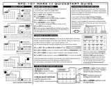
Power Supply
Power needs to be supplied via the M8 connector. This connector also
provides access to analog I/O signals, see Table 4-1.
Figure 4-1: EtherNet/IP Top Cover
Figure 4-2: M8 Male Device Connector Pin Layout,
Pin Side View
Table 4-1: Pin Labeling of M8 Male Device and Female Mating Cable Connector
Pin Label
Function at Remote Connector
V+
Positive Power Supply Voltage
V-
Power Supply Ground
N/C
Not Connected
SLA58xx Top Cover
10
SLA58xx

M8 mating cables can be purchased as a second line item, details given below.
Figure 4-3: M8 Female Mating Cable
Figure 4-4: M8 Female Mating Cable Connector Pin Layout
Network
Table 4-2: Wire Labeling of M8 Female Mating Cable Connector
Wire Color
Wire Label
Function at Remote Connector
Blue
V
Power Supply Ground
Brown
V+
Positive Power Supply Voltage
Black
N/C
Not Connected
White
N/C
Not Connected
Grey
N/C
Not Connected
11

Section 4 Quick Start
Table 4-3: M8 Female Mating Cable Part Numbers
Supplier
Part Number
Description
Brooks
Instrument
124X049AAA
M8 Mating Cable 2m
124X050AAA
M8 Mating Cable 5m
124Z170AAA
ECAT to DB15 Male
Each SLA5800 Series EtherNet/IP
TM
device has (2) RJ-45 Ethernet
Connection ports labeled 1 and 2. Network connections can be made to
either or both ports, depending on the network topology. The SLA5800
Series EtherNet/IP
TM
device
will support star, linear and DLR topologies.
Click the following reference for more detailed information on EIP topologies
and their implementation EtherNet/IP Embedded Switch Technology.
The SLA5800 Series EtherNet/IP
TM
device
supports auto-negotiation of the
communications link. Both ports support data rates of 10/100 Mbps and
Half/Full duplex communications. The device may be directly connected to
the Ethernet NIC on a desktop or laptop PC for configuration and
commissioning activities
MOD LED
Table 4-4: MOD LED Indicator Definitions
Indicator State
Summary
Requirement
Off
No power
No power is supplied to the device.
Green
Device Operational
Device is operating correctly.
Flashing Green
Standby
Device has not been configured.
Flashing Red
Major Recoverable
Fault
The device has detected a Major Recoverable Fault (Alarm)
Red
Major Unrecoverable
Fault
The device has detected a Major Unrecoverable fault (Error)
Flashing Green / Red
Self-test
The device is performing its power-up testing.
12

Section 4 Quick Start
NET LED
Table 4-5: NET LED Indicator Definitions
Indicator State
Summary
Requirement
Off
Not powered, or no IP
address
The device is powered off or is powered on but with no IP address
configured.
Flashing Green
No connections
An IP address is configured, but no CIP connections are established with
the device.
Steady Green
Connected
An IP address is configured, at least one CIP connection (any transport
class) is established with the device.
Flashing Red
Connection timeout
An IP address is configured, and an Exclusive Owner connection has
timed out. The NET indicator will return to steady green when the
Exclusive Owner connection is reestablished.
Steady Red
Duplicate IP
The device has detected that its IP address is already in use.
Flashing Green / Red
Self-test
The device is performing its power-up testing.
TCP/IP Network Configuration
The TCP/IP network settings can be configured using a web browser
interface or through a variety of network utilities. By default, SLA5800
Series EtherNet/IP
TM
MFC is shipped with DHCP enabled. If no DHCP
server is available on the network, the device defaults to the following
TCP/IP connections settings:
IP Address: 192.168.1.100
NET Mask: 255.255.255.0
Gateway Address: 0.0.0.0
DNS1: 0.0.0.0
DNS2: 0.0.0.0
To configure using a web browser, connect the device to the network that is
configured with the same subnet as the device (192.168.1.xxx). Open the web
browser and enter the IP address of the device as the URL. The following will be
displayed:
13

Section 4 Quick Start
By default, DHCP is selected. To manually configure the network settings, select
the ‘Store Value’ radio button. The network configuration fields will become
active. Click ‘Submit’ after setting the network configuration.
NOTE: Once the settings have been changed, the TCP/IP address will need to
be reentered in the URL field of the browser to reconnect with the device and
confirm the network settings.
Class 1 Implicit Connection
For quick start, the following connection configuration, “Class 1
Connections,” can be used to create a Class 1, Implicit connection. See
Section 5 for more information on other Class 1, Implicit connections.
See Appendix A for details on Class 1 Implicit Connection Types.
MFC
Table 4-6: MFC Exclusive Owner Connection Configuration
Input
3
Assembly ID
101
Input Assembly Size
See Section 5.3 for Assembly 101 Size
Input Assembly RPI
> = 50 msec
Output
3
Assembly
201
Output Assembly Size
See Section 5.3 for Assembly 201 Size
Output Assembly RPI
>= 50 msec
Configuration Assembly
1
100
Configuration Assembly Size
2
See Section 5.3 for Configuration Assembly 100 Size
1.
If no configuration data is to be transferred to the device, set the configuration assembly ID to 0 with a data length of 0.
2.
All field values in the configuration assembly data must have valid values or the assembly data will be rejected along with the
connection open request.
3.
The terms Input/Output are relative to the device
14

MFM
Table 4-7: MFM Input Only Connection Configuration
Input Assembly ID
102
Input Assembly Size
See Section 5.3 for Assembly 102 Size
Input Assembly RPI
> = 50 msec
Output Assembly
203
Output Assembly Size
See Section 5.3 for Assembly 203 Size
Output Assembly RPI
>= 50 msec
Configuration Assembly
1
100
Configuration Assembly Size
2
See Section 5.3 for Configuration Assembly 100 Size
1.
If no configuration data is to be transferred to the device, set the configuration assembly ID to 0 with a data length of 0.
2.
All field values in the configuration assembly data must have valid values or the assembly data will be rejected along with
the connection open request.
3.
The terms Input/Output are relative to the device
Class 3 Explicit Connection
The SLA5800 Series EtherNet/IP™ devices support Class 3 explicit
connections. See Section 6 for details on supported objects and attribute
definitions in the device.
15

Section 5 Configuration
Section 5: Configuration
Commonly Configured Attributes
EtherNet/IP™
provides several ways to configure a device. As noted in
the previous sections, a configuration assembly can be used when
establishing Class 1 implicit connections, or alternatively, Class 3 Explicit
connections can be used to set/get individual parameters
ODVA also defines Electronic Data Sheets (EDS) that specify the
connections and parameters that are available in the device. The
SLA5800 Series EtherNet/IP
TM
device has an EDS file and is available at
https://www.brooksinstrument.com/en/products/accessories-
software/digital-communication-system-files/ethernetip. Your EIP network
configuration tool may be able to read EDS files directly to facilitate the
configuration process.
The SLA5800 Series MFC/MFM supports many different configurable
attributes. The out-of-box defaults meet the needs of a great majority of
applications, but some applications may require the device to report more
information or behave differently than is configured with default settings,
such as valve position, safe mode, flow and/or setpoint engineering units,
etc.
This section covers the more common attributes that are configured to
meet the unique needs of applications. The terms “attribute” and
“parameters” can be used interchangeably and ultimately refer to the
same data item within the MFC device. The term “parameter” is widely
used within the EDS paradigm whereas “attribute” is used within the
ODVA specification.
The following tables will reference both the EDS Parameter name (if
the configuration software utilizes the EDS sheet) and the EPATH
descriptor (class-instance-attribute) for those who are writing custom
or have other types of configuration interfaces.
16

Section 5 Configuration
Table 5-1: Commonly Configured Attributes/Parameters
Attribute
EDS Parameter
EPATH
Default
Semantics
Flow Meter Data
Units
Flow_Unit
[0xA9-1-4]
4103 (0x1007)
See Section 5.1.1 Data
Units
Flow Controller Data
Units
Ctrl_Units
[0x9E-1-4]
4103 (0x1007)
See Section 5.1.1 Data
Units
Temperature Meter
Data Units
Temp_Units
[0xA4-1-4]
4608 (0x1200)
See Section 5.1.1 Data
Units
Selected Gas
Calibration
Cal_Instance
[0xA9-1-35]
1
The instance of the
Gas Calibration
Object used to
linearize the Flow
Sensor
Valve Driver Safe
State
Safe_State
[0x96-1-21]
0 (Close)
The valve will close
when the device is in
its Safe State
Status Alarm Mask
Alarm_Mask
[0xB8-1-8]
0x00000000
All Alarm Bits are
masked
Status Warning Mask
Warning_Mask
[0xB8-1-9]
0x00000000
All Warning Bits are
masked
Data Units
The SLA5800 Series MFC can report flow and accept setpoints in values
associated to engineering units. This can simplify user interpretation of
information from the device by letting the device perform the calculations
necessary to interpret the flow signal from its internal sensor based upon
information in the selected calibration.
Table 5-2: Configurable Data Units Attributes
Parameter
EPATH
Applicable Units Table
Out-of-Box
Default
Flow Sensor Data Units
[0xA9-1-4]
Appendix C: Volumetric Flow Units Table
Percent
Flow Totalizer Data Units
[0xA9-1-125]
Appendix C: Volume Units Table
Liters
Flow Control Data Units
[0x9E-1-4]
Appendix C: Volumetric Flow Units Table
Percent
Temperature Data Units
[0xA4-1-4]
Appendix C: Temperature Units
deg C
17

Section 5 Configuration
Operational Modes
All products in the SLA5800 Series product line employ an internal State
Machine to govern the operational mode of the device. One particular
operational mode is the Safe Mode (a.k.a. the Safe State). For MFC(s),
Safe Mode stops the interface controller and forces the valve actuator to a
define state. By default, the valve actuator will be closed. The state of the
actuator in Safe Mode can be configured in the Valve Actuator object,
parameters [0x96-1-21] and [0x96-1-22].
The device will be in Safe Mode when anyone of the following conditions
exist:
• If any Error Status bit is set [0xB8-1-4], the device will remain in
Safe Mode or will transition out of the Executing State to the Safe
Mode, regardless of the establishment of the Class 1 implicit
connection or directive to the Device Management object.
• Provided all Error Status bits are clear, the establishment of a
Class 1 implicit connection to the device will control the mode
of the device.
1
• If the Class 1 implicit connection is closed or times out, the
device will transition out of the Executing State to the Safe Mode.
• Provided all Error Status bits are clear, and the Class 1 Implicit
connection does not exist, moving in/out of the Executing state
can be achieved using Start/Stop directives to the Device
Management object. See section TBD on using these directives.
1
The Class 1 Implicit Exclusive Owner connection message to the target device contains a header with certain flags required by the
target device for proper operation. One of these flags is the Run/Idle flag. Setting of the Run/Idle flag is a function of the master
scanner software. Consult your specific master scanner tools for setting this flag. One example would be changing the run mode of
a PLC (run mode or program mode) would set/clear this flag. If the Run/Idle flag is set to Run, the device will be in the Executing
State, otherwise the device will be in the Safe
State.
18

Valve Safe Mode
Attribute Actuator Safe State in Valve Driver Object [0x96-1-21]. These
states apply to both Normally Closed and Normally Open Valves.
Table 5-3: Safe State
Value
State
0
Closed (default)
1
Open
2
Hold
3
Use Safe Value
Gas Page Calibration Configuration
If the MFC/MFM contains multiple calibrations, the selection of a particular
calibration can be configured in attribute Calibration Instance of the Flow
Meter Object [0xA9-1- 35].
The value of this attribute is limited to the number of Flow Calibration
Objects configured in the device. The minimum value is 1, which is also
the default value.
Class 1 Connections
The following tables describe the available Class 1 connection configurations in the device. See section TBD
for assembly sizes and details on the data fields within each assembly.
MFC
Table 5-4: MFC Class 1 Connection Configurations
Name
Connection Type
Configuration Assembly
Output (Consume)
Assembly
Input
(Produce)
Assembly
Ctrl/Mon XO
Exclusive Owner
100
101
201
Process Data 1 I/O
Input Only
-
300
201
Process Data 2 I/O
Input Only
-
301
202
Process Data 1 L/O
Listen Only
-
302
201
Process Data 2 L/O
Listen Only
-
303
202
19

Section 5 Configuration
MFM
Table 5-5: MFC Class 1 Connection Configurations
Name
Connection Type
Configuration
Output (Consume)
Input
(Produce)
Process Data 1 XO
Exclusive Owner
100
102
203
Process Data 2 I/O
Input Only
-
300
201
Process Data 1 I/O
Input Only
100
301
203
Process Data 2 L/O
Listen Only
-
300
201
Process Data 1 L/O
Listen Only
-
301
203
Data Assemblies
Configuration Assembly
The configuration assembly can be used to get or set configuration values in the
device. Depending on the application tools for the master scanner, this
configuration data can be sent to the device when Class 1 connections are
created with the device. This data can also be accessed through explicit
message exchanges by reading or writing class 4, instance 100, attribute 3. If
the configuration data is sent to the device using this assembly, all the data fields
in the assembly must be a valid value otherwise all the data will be rejected.
Refer to the object definitions for more information on parameter in this
assembly.
Instance ID: 100
Device Type: MFC
Assembly Size: 168 Bytes / 42 Words
Table 5-6: MFC Configuration Assembly Definition
Parameter
Class
Inst
ID
Data Type
Data
Size
Description
Flow Data Units
169
1
4
DINT
4
Flow Engineering Units
Totalizer Units
169
1
125
DINT
4
Totalizer Engineering Units
Calibration
Instance
169
1
35
DINT
4
Selected Process Gas Instance
Flow Alarm Trip
Point High
169
1
17
REAL
4
High Flow Alarm Trip Point
Flow Alarm Trip
Point Low
169
1
18
REAL
4
Low Flow Alarm Trip Point
Flow Alarm
Hysteresis
169
1
19
REAL
4
Flow Alarm Hysteresis.
Flow Alarm Settling
Time
169
1
20
DINT
4
Flow Alarm Settling Time
Flow Warning Trip
Point High
169
1
21
REAL
4
High Flow Warning Trip Point
Flow Warning Trip
Point Low
169
1
22
REAL
4
Low Flow Warning Trip Point
Flow Warning
Hysteresis
169
1
23
REAL
4
Flow Warning Hysteresis
Flow Warning
Settling Time
169
1
24
DINT
4
Flow Warning Settling Time
20
/