INSTALLATION AND USER GUIDE FOR 20/40/60-MINUTE PUSH-BUTTON TIMER
VENMAR NO. 03364 AND VÄNEE NO. 03701
READ AND SAVE THESE INSTRUCTIONS
Always disconnect the unit before making any connections. Failure in disconnecting power could result in electric
shock or damage of the wall control or electronic module inside the unit.
WARNING
!
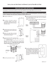
Cut a 2³/8” x 1³/8” hole in a wall, at
a convenient location for the push
button. Route a cable (type 22/4) for the
push-button from the unit to this hole.
See figure at right.
Temporarily place the push button over
the hole and mark both mounting screw
hole positions.
Remove the push button, drill both screw
holes (3/16” Ø) in wall and insert the wall
anchors (included).
Strip the end of the cable to access the wires.
NOTE: Although this is a 4-wire cable, only 3 of them will be
used for connection.
Strip the end of 3 wires. Connect wires to the terminals,
regardless of the wire color: one wire to “OL’’, another one to
“OC’’ and a last one to “I’’. Note which wire color has been
chosen for each terminal. See illustration below.
IOC
OL
20/40/60-MINUTE PUSH-BUTTON TIMER
REAR VIEW
VE0279A
First wire
Fourth wire
(NOT USED)
Third wire
Second wire
VC0134A
Ø 3/16", typ.
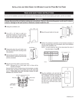
Unplug the ventilation unit.
Mount the push button to the wall.
Perform the electrical connection to the terminal connector of the
unit, as shown below. For more details, refer to the installation
manual of the ventilation unit.
NOTE: To avoid miswiring, refer to the notes about the color of
the wires taken on step
.
NO C NC I OC OL Y R G B
20/40/60-MINUTE PUSH-BUTTON TIMER
REAR VIEW
VE0277A
IOC
OL
Plug the ventilation unit and test the
push button.
High speed activation times are in
multiples of 20 minutes.
• Within two seconds, push once for
20-minute, twice for 40-minute, or
three times for 60-minute activation.
Indicator then lights up and the
system exchanges air at high speed.
• Every five seconds, the indicator light
flashes once to indicate a 20-minute
selection, twice for a 40-minute and
three times for a 60-minute selection.
• Push once more to stop activation.
Unit then returns to its to previous
setting.
The illustrations in this document are generic; your push button appearance may be slightly different from the ones shown.
20256 rev. 01
9
8
7
6
5
4
3
2
1
OL
OC
I
1 4 7
2 5 8
3 6 9
J3
P C BOARD
J1
VE0278A
B
G
R
Y
20/40/60-MINUTE PUSH-BUTTON TIMER
REAR VIEW
IOC
OL
ACTUAL
MODELS
EARLIER
MODELS
VC0136