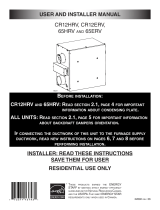
Venmar Novofit 1.0 HRV Installation guide
- Type
- Installation guide
Venmar Novofit is an energy-efficient and cost-effective ventilation system that provides many features to improve your home's air quality. The Novofit 1.0 HRV is an ideal choice for any home, as it can help reduce energy costs, improve indoor air quality and provide a more comfortable living environment. Some of its most notable features and capabilities include:
- Improved indoor air quality: The Venmar Novofit 1.0 HRV helps to improve indoor air quality by removing stale air and pollutants from your home, and replacing it with fresh, filtered air.
- Reduced energy costs: The Novofit is a highly-efficient system that can help you save money on your energy bills as it uses a heat recovery core to transfer heat from the exhaust air to the incoming fresh air, reducing the amount of energy needed to heat your home in the winter.


-
 1
1
-
 2
2
-
 3
3
-
 4
4
-
 5
5
-
 6
6
-
 7
7
-
 8
8
-
 9
9
-
 10
10
-
 11
11
-
 12
12
-
 13
13
-
 14
14
-
 15
15
-
 16
16
-
 17
17
-
 18
18
-
 19
19
-
 20
20
-
 21
21
-
 22
22


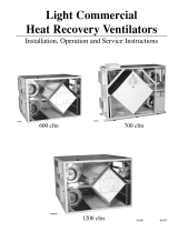
Venmar Novofit 1.0 HRV Installation guide
- Type
- Installation guide
Venmar Novofit is an energy-efficient and cost-effective ventilation system that provides many features to improve your home's air quality. The Novofit 1.0 HRV is an ideal choice for any home, as it can help reduce energy costs, improve indoor air quality and provide a more comfortable living environment. Some of its most notable features and capabilities include:
- Improved indoor air quality: The Venmar Novofit 1.0 HRV helps to improve indoor air quality by removing stale air and pollutants from your home, and replacing it with fresh, filtered air.
- Reduced energy costs: The Novofit is a highly-efficient system that can help you save money on your energy bills as it uses a heat recovery core to transfer heat from the exhaust air to the incoming fresh air, reducing the amount of energy needed to heat your home in the winter.
Ask a question and I''ll find the answer in the document
Finding information in a document is now easier with AI
Related papers
-
 Venmar 20-minute lighted push button for EVO5 500 HRV or EVO5 700 HRV HEPA User guide
-
 Venmar 20-minute lighted push button User guide
-
Venmar 20/40/60-minute lighted push button User guide
-
 Venmar K7 HRV User guide
-
 Venmar CR12 ERV User guide
-
 Venmar Ventilation Hood 1200 cfm User manual
-
 Venmar Constructo 1.5 ES HRV User guide
-
 Venmar FAE125M User guide
-
 Venmar Kubix HRV Installation guide
-
 Venmar PRO215 User guide


Other documents
-
Deco DW824 & DD850 User guide
-
FIELD CONTROLS HRV / ERV Models FC150HRV/ERV & FC200HRV/ERV Installation guide
-
-
TP-LINK Deco X50-Outdoor User guide
-
Lifebreath 100 FN User manual
-
Carrier HRVCCLVU1200 Installation, Start-Up, And Operating Instructions Manual
-
-
Lifebreath METRO 120ERVD-ECM Installation guide
-
Carrier HRVCCSHB1100 User manual
-
Lifebreath RNC120F User manual