Page is loading ...

#
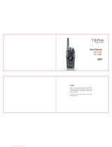
Portable Radios
GP 68
User Manual

NOTE
Keep this page open for easy reference as you go
through the user guide.
1. On / Off and Volume Knob 13. Backspace Button
2. Channel Selector Knob 14. Left Scroll Button
3. Antenna Connector 15. Right Scroll Button
4. Toggle Light / Enter Button 16. Accessory Connector
5. Monitor Button 17. SCI Port
6. Push-To-Talk (PTT) Button 18. LCD Screen
7. Signal Button 19. Numeric Keypad
8. Squelch Button 20. Enable / Disable PTT ID Key
9. Low Power Button 21. Lock / Unlock Key
10. Scan / Nuisance Delete Button 22. Battery Pack
11. Microphone 23. Battery Latches
12. Speaker
4
#
1
7
8
9
11
1
0
12
15
13
14
18
19
20
21
23
22
1
6
1
7
1
2
1
0
2
1
7
8
9
11
1
0
12
15
13
14
18
23
22
2
3
6
5
5
4
6
3

Copyright Information
The Motorola products described in this manual may
include copyrighted Motorola computer programs
stored in semiconductor memories or other mediums.
Laws in the United States and other countries pre-
serve for Motorola certain exclusive rights for copy-
righted computer programs, including the exclusive
right to copy or reproduce in any form the copyrighted
computer program. Accordingly, any copyrighted
Motorola computer programs contained in the Motor-
ola products described in this instruction manual may
not be copied or reproduced in any manner without the
express written permission of Motorola. Furthermore,
the purchase of Motorola products shall not be
deemed to grant either directly or by implication,
estoppel, or otherwise, any license under the copy-
rights, patents, or patent applications of Motorola,
except for the normal non-exclusive, royalty fee license
to use that arises by operation of law in the sale of a
product.
© 1997 by Motorola, Inc.
All Rights Reserved.
Motorola Malaysia Sdn. Bhd. (Company No. 12631DE),
Bayan Lepas Free Industrial Zone, Phase III,
11900 Penang, Malaysia.
Printed in Malaysia.
Motorola, APC, Adaptive Power Control™
Technology and Channel Scan are trademarks of
Motorola, Inc.

Contents
1
Contents
Introduction . . . . . . . . . . . . . . . . . . . . . . . . . . . . . . . . . . 2
Packing Information. . . . . . . . . . . . . . . . . . . . . . . . . . . . 3
Knobs, Buttons, Connectors and Others. . . . . . . . . . . . 4
Getting Started . . . . . . . . . . . . . . . . . . . . . . . . . . . . . . . 8
Basic Operations. . . . . . . . . . . . . . . . . . . . . . . . . . . . . 14
Turning the Radio On . . . . . . . . . . . . . . . . . . . . . . . 14
Turning the Radio Off . . . . . . . . . . . . . . . . . . . . . . . 14
Adjusting the Volume . . . . . . . . . . . . . . . . . . . . . . . 14
Selecting a Channel . . . . . . . . . . . . . . . . . . . . . . . . 14
High / Low Power Output . . . . . . . . . . . . . . . . . . . . 15
Transmitting . . . . . . . . . . . . . . . . . . . . . . . . . . . . . . 15
Receiving . . . . . . . . . . . . . . . . . . . . . . . . . . . . . . . . 16
Additional Operations . . . . . . . . . . . . . . . . . . . . . . . . . 17
Display Backlight . . . . . . . . . . . . . . . . . . . . . . . . . . 17
PTT ID . . . . . . . . . . . . . . . . . . . . . . . . . . . . . . . . . . 17
Locking / Unlocking the Radio’s Function. . . . . . . . 18
Changing Squelch Modes. . . . . . . . . . . . . . . . . . . . 18
Setting Squelch Level. . . . . . . . . . . . . . . . . . . . . . . 20
Scan Operations . . . . . . . . . . . . . . . . . . . . . . . . . . . . . 21
DTMF Telephone Interconnect . . . . . . . . . . . . . . . . . . 23
Voice Selective Call (Optional) . . . . . . . . . . . . . . . . . . 27
Special Programming Mode (SPM). . . . . . . . . . . . . . . 29
SPM Browse Menu. . . . . . . . . . . . . . . . . . . . . . . . . 30
LCD Segments and Indicators. . . . . . . . . . . . . . . . . . . 38
Alert Tone Indicators . . . . . . . . . . . . . . . . . . . . . . . . . . 39
Radio to Radio Cloning . . . . . . . . . . . . . . . . . . . . . . . . 41
Information For Safe, Efficient Operation . . . . . . . . . . 43
Recycling / Disposal of NiCd Batteries . . . . . . . . . . . . 46
Licensing & Service Information . . . . . . . . . . . . . . . . . 48
Troubleshooting. . . . . . . . . . . . . . . . . . . . . . . . . . . . . . 49
Accessories. . . . . . . . . . . . . . . . . . . . . . . . . . . . . . . . . 54

Introduction
2
Introduction
Congratulations on your purchase of a Motorola two-
way radio. Your radio is a product of Motorola’s more
than 50 years of experience as a world leader in the
designing and manufacturing of communications
equipment. This radio offers superior quality, superior
performance, ultimate flexibility and years of reliable
and effective communications.
This radio incorporates the latest technology available
in two-way radio communications. The use of micro-
computer technology makes changing radio character-
istics such as operating frequencies and squelch
codes both economical and fast. Any computer
equipped dealer can easily reprogram your radio’s
operating characteristics.
The radio meets tough environmental demands while
providing cost-effective and reliable communications.
It meets established standards for low pressure, high
temperature, low temperature, temperature shock,
solar radiation, rain, humidity, salt fog, dust, vibration,
and shock. This radio also meets the Electronic Indus-
try Association RS316B electrical and mechanical
specifications. The Motorola Accelerated Life Test
(ALT) assures that possible failures brought on by field
stress and abuse are identified and designed out of
your radio before it reaches your hands.
All of these features provide for better, yet more cost
effective communications for you.
Coverage of this User Guide
This user guide describes the operation of radios with
and without a keypad.
NOTE
The keypad symbol shown here indicates
that the feature is only available on radios
with keypads. This will be the convention
used throughout this user guide.
#

Packing Information
3
Packing Information
When you receive your packaged Motorola radio,
inspect the shipping carton for any signs of damage.
Next, remove and check the contents of the packing
case to be sure that all items ordered have been
included
.
Standard Packaged Model Contents
• Keypad Radio or Non-Keypad Radio
• Battery
• Antenna
• Fixed Belt Clip
• User Manual
Inspect the equipment thoroughly. If any part of the
equipment has been damaged in transit, report the
extent of the damage to the transportation company
immediately.
NOTE
The radio as shipped accepts rechargeable NiCd
battery cell-pack (available as standard or high
capacity packs). Please refer to page 54 for a com-
plete list of available accessories.
#
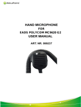
Antenna
Keypad Radio Non-Keypad Radio
Fixed
Either Or
Belt Clip
Battery

Knobs, Buttons, Connectors and Others
4
Knobs, Buttons, Connectors and Others
NOTE
The numbers in brackets below refer to the loca-
tions of the control buttons, knobs, etc. as shown in
the illustration on the inside front cover.
On / Off and Volume Knob (1)
Turns the radio on and off and adjusts the volume
level.
Channel Selector Knob (2)
➊Selects the channel and squelch level.
➋Changes the direction of scanning when the radio
is in scan mode.
Antenna Connector (3)
Connects antenna to the radio.
Toggle Light / Enter Button (4)
➊Toggles display backlight status.
➋Confirms user input (quick press).
Monitor Button (5)
Monitors the channel for activities (squelch is dis-
abled).
Push-To-Talk (PTT) Button (6)
➊Push to talk, release to listen.
➋Press and hold when making DTMF dialling.

Knobs, Buttons, Connectors and Others
5
Signal Button (7)
,
➊Toggles between
Carrier
,
Coded
(
PL / DPL
), and
Signalling Squelch
modes.
➋DTMF (Dual Tone Multiple Frequencies) digit ‘A’.
Squelch Button (8)
,
➊Selects Carrier Squelch level.
➋DTMF digit ‘B’.
Low Power Button (9)
,
➊Toggles between high and low transmit power.
➋DTMF digit ‘C’.
Scan / Nuisance Delete Button (10)
,
➊Enables / disables scanning (quick press).
➋Deletes a Nuisance Channel (long press).
➌DTMF digit ‘D’.
Microphone (11)
Used in the process of transmitting messages.
Speaker (12)
Used in the process of receiving messages.
Backspace Button (13)
,
When editing phone numbers and IDs, this key acts
as a backspace (rub-out) key.
A
SIG
B
SQL
C
LOW
N-DEL
D
SCAN

Knobs, Buttons, Connectors and Others
6
Left Scroll Button (14)
,
Scrolls to the left when editing phone numbers and
IDs.
Right Scroll Button (15)
, (non-keypad models)
(keypad models)
➊Scrolls to the right when editing phone numbers
and IDs.
➋If held on power-up, radio enters into
Special Pro-
gramming
mode.
➌Stores / recalls phone numbers, phone access and
phone deaccess code (keypad models only).
Accessory Connector (16)
Connects accessories such as remote speaker
microphone or external handset to radio.
SCI Port (17)
Used to service and to clone the radio.
LCD Screen (18)
Displays information about the current state of the
radio (see
“LCD Segments and Indicators”
on
page 38).
NOTE
Items 19 to 21 are only applicable to keypad /
display models.
Numeric Keypad (19)
DTMF digits ‘0’ to ‘9’.
ME
M

Knobs, Buttons, Connectors and Others
7
Enable / Disable PTT ID Key (20)
,
➊Enables / disables PTT ID (long press).
➋DTMF digit ‘#’.
➌Pressing this key after sends the programmed
phone deaccess code.
➍Pressing this key immediately following ,
inserts a pause.
Lock / Unlock Key (21)
,
➊Locks / unlocks the keypad (long press).
➋DTMF digit ‘
∗’.
➌Pressing this key after sends the programmed
phone access code.
Battery Pack (22)
Power supply to the radio.
Battery Latches (23)
For attaching battery tray / pack to the radio.
ME
M
ME
M

Getting Started
8
Getting Started
Attaching and Removing the Antenna
Attaching
➊
Fasten the antenna to the radio by placing the
threaded end of the antenna into the Antenna Con-
nector (3).
➋
Rotate the antenna clockwise until tight.
Removing
• Turn the antenna in an anti-clockwise direction until
it disengages from the radio.
Attaching and Removing the Belt Clip
Attaching
➊
Align mounting rails of the radio with the grooves of
belt clip.
➋
Slide belt clip downwards until it clicks into place.
Removing
➊
Insert the end of a key between the release tab
and the back surface of the radio.
➋
Lift the release tab; slide the belt clip upwards.
Installing and Removing Batteries
Installing
➊
Align the Battery Pack (22) with the back of the
radio.
➋
Slide the Battery Pack (22) into place.

Getting Started
9
Removing
➊
Release the Battery Latches (23).
➋
Slide the Battery Pack (22) away from the radio.
Charging NiCd Battery Pack
Before using your radio with a rechargeable (NiCd)
battery, you must charge the battery.
WARNING
DO NOT attempt to charge your radio if you are
using alkaline batteries. Doing this may cause the
batteries to leak or explode, leading to severe skin
burns or eye injuries.
IMPORTANT
Transmitting a message while your radio is charg-
ing can cause the radio or the charger to operate
improperly. DO NOT transmit when your radio is
charging.
NOTE
Your radio may take twice as long to charge if it is
not turned off during charging.

Getting Started
10
Charging your Battery for the FIRST time
New batteries are supplied in a totally uncharged
state. To ensure maximum battery performance, a new
battery MUST be FULLY charged. Refer to the fol-
lowing table for guidelines.
Table 1: Length of time required to fully charge a new
battery
Charging your Battery Subsequently
Refer to the following table for guidelines on recharg-
ing your batteries.
Standard
Capacity
NiCd Battery
Pack
High
Capacity
NiCd
Battery Pack
Wall Charger (with/
without Wall
Charger Base)
16 hours 20 hours
Standard Desktop
Charger
16 hours 16 hours
Quick Charge
Desktop Charger
16 hours 16 hours

Getting Started
11
Table 2: Length of time required to fully recharge a
used battery
NOTE
A battery that is left unused for several months will
be completely discharged. In this case, follow
guidelines in Table 1 on page 10 to recharge the
battery.
Charging with Wall Charger
➊
Make sure the battery pack is attached to the
radio.
NOTE
With the Charger Base, the battery can be charged
when connected or not connected to the radio.
➋
Turn the radio off (if it is turned on).
Standard
Capacity
NiCd Battery
Pack
High
Capacity
NiCd Battery
Pack
Wall Charger (with/
without Wall
Charger Base)
10 hours 20 hours
Standard Desktop
Charger
10 hours 10 hours
Quick Charge
Desktop Charger
3 hours 3 hours

Getting Started
12
If not using the Charger Base:
➌
Lift the dust cover covering the Accessory Connec-
tor (16).
➍
Insert one end of the Wall Charger into the lower
port of the Accessory Connector (16), and the
other into an electrical outlet.
If using the Charger Base:
➌
Insert the radio / battery into the charging docket.
➍
Refer to Table 1 and 2 on pages 10 and 11 for an
estimation of the duration involved for charging the
battery pack.
➎
Unplug the Wall Charger from the radio when
charging is complete.
NOTE
The LED on the
Wall Charger
is lit (red) continu-
ously during charging.
Charging with Desktop Charger
NOTE
With Desktop Chargers, the battery can be charged
when connected or not connected to the radio.
➊
Place the Charger Insert into the Desktop Charger.

Getting Started
13
➋
Insert the radio / battery into the charging docket.
If using the Quick Charge Desktop Charger:
➊
Press the Quick Charge button.
➋
Refer to Table 1 and 2 on pages 10 and 11 for an
estimation of the duration involved for charging the
battery pack.
➌
Remove the radio / battery from the charger when
charging is complete.
NOTE
The LED on the charger lights up continuously dur-
ing charging. For the Standard Desktop Charger, it
is red for the whole charging period. For the Quick
Charge Desktop Charger, it changes from yellow
(before charging begins) to red (during charging) to
green (when charging is completed).
CAUTION
The Quick Charge Desktop charger runs on a 3-
hour timer which begins counting each time you
press the
Quick Charge
button
.
Removing the bat-
tery or radio from the charger before the battery is
fully charged, or removing and replacing battery /
radio repeatedly during charging, and then press-
ing the
Quick Charge
button again can overcharge
or damage the battery. Press the
Quick Charge
but-
ton only when the battery needs to be fully
charged.

Basic Operations
14
Basic Operations
Turning the Radio On
• Rotate the On / Off and Volume Knob (1) clock-
wise to turn the radio on.
Turning the Radio Off
• Rotate the On / Off and Volume Knob (1) anti-
clockwise until a click is heard to turn the radio off.
Adjusting the Volume
• Rotate the On / Off and Volume Knob (1) clock-
wise to increase your radio’s volume level, or anti-
clockwise to decrease it.
NOTE
To do an initial setting of the volume, press and
hold the
Monitor Button (5)
until the background
noise is heard. Continue holding the
Monitor But-
ton (5)
while adjusting to the desired volume.
Selecting a Channel
The radio is preconfigured by the dealer for use with
your communications system. Up to 20 programmed
channels may be available. Each channel consists of a
frequency pair - one transmit frequency and one
receive frequency.
• Rotate the Channel Selector Knob (2) to the
desired channel.
The
LCD Screen (18)
shows the channel that the
radio is operating on.

Basic Operations
15
NOTE
Empty memory / unprogrammed channels are not
displayed.
High / Low Power Output
• Press to toggle between high and low power
output levels.
NOTE
The indicator LOW lights up on the
LCD Screen
(18)
when the radio is operating in
low power
mode.
NOTE
High power mode can improve the clarity of voice
activity in areas where signals are weak while low
power mode extends battery life.
Transmitting
➊
Select the desired channel by rotating the Chan-
nel Selector Knob (2).
➋
Press and hold the Monitor Button (5), and listen
for channel activity.
➌
If the channel is clear, press the Push-To-Talk
(PTT) Button (6) and speak clearly into the Micro-
phone (11) (see “Information For Safe, Efficient
Operation” on page 43 for more information).
C
LOW
TX

Basic Operations
16
NOTE
Unless disabled (‘dot’ indicator flashes on the
LCD
Screen (18)
),
PTT ID tones
are heard as they are
being transmitted (see “
PTT ID”
on page 17). You
can start your conversation when the tones end.
NOTE
The ‘TX’ indicator lights up on the
LCD Screen (18)
when the
Push-To-Talk (PTT) Button (6)
is pressed.
IMPORTANT
Whenever you transmit a message, you are using
the resources of the transmitting channel. Speaking
for long periods of time would deprive others from
using that channel.
NOTE
The maximum duration for transmission is deter-
mined by the value of the
Time-Out-Timer
(see “
Edit-
ing the Time-Out Timer Duration”
on page 33).
Once you reach the time limit, a
Time-Out Timer Alert
tone
is sounded, and the transmission is cut off.
Receiving
• If the Push-To-Talk (PTT) Button (6) is pressed,
release it and listen for incoming messages.
NOTE
Make sure the volume level is set properly, or else
you may receive a message but are unaware about it.

Additional Operations
17
Additional Operations
Display Backlight
• Press the Toggle Light / Enter Button (4) to turn on /
off the backlight.
NOTE
To conserve power, the backlight is programmed to
automatically turn off after 5 seconds.
NOTE
Pressing either the
Push-To-Talk (PTT) Button (6)
or the
Monitor Button (5)
has no effect on the back-
light.
PTT ID
If programmed, the radio transmits a DTMF identifica-
tion code (unit ID), indicating which portable is in oper-
ation.
During a conversation, the code is normally sent only
on the initial
Push-To-Talk (PTT) Button (6)
press
(unless PTT ID has been disabled). The ‘TX’ indicator
lights for the duration of the PTT ID. If there is no PTT
or receive activity for 7 seconds, or if you change the
channel (or scan resumes), the PTT ID is once again
transmitted on the next
Push-To-Talk (PTT) Button (6)
press.
• Press and hold to enable / disable PTT ID.
NOTE
Upon pressing , you will hear a beep. Hold the
button down until you hear a second beep, indicat-
ing that the PTT ID status has been changed.
When PTT ID is
disabled
, the ‘dot’ indicator flashes
on the display (To enable / disable PTT ID on non-
keypad radios, please contact your dealer).
#
/