Page is loading ...

USER 1 - 24V DG R1
Sistemi Elettronici
di Apertura Porte e Cancelli
International registered trademark n. 804888
®
REV 03 - 11/2014
Italiano
English
Français
Español
APPAR. ELETTRONICA 24V PER PORTE DA GARAGE
24V ELECTRONIC CONTROL UNIT FOR GARAGE DOOR
ARMOIRE ELECTRONIQUE 24V
DISPOSITIVO ELECTRÓNICO 24V
POUR PORTE DE GARAGE
PARA PUERTAS SECCIONALES Y BASCULANTES
67411370
SEA S.p.A.
Zona Ind.le S. Atto - 64020 S. Nicolò a Tordino (TE)
Tel. 0861.588341 - Fax 0861.588344
www.seateam.com
e-mail: [email protected]

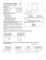
CN1 = Input/Output connector
CN3 = Jolly-Jolly 2 connector
CN4 = Encoder connector
CN5 = Courtesy light output plug
CN6 = Motors connector
CN7 = Batteries connector
CN8 = Power connector
CNA = Receiver connector RX
CNP = Programming connector
EXP = External module connector
OK = Programming button
DOWN = Programming button
UP = Programming button
RD1 =Motors piloting Mosfet
RD3 = Motors piloting Mosfet
R1 = Motors command relay
R2 = Motors command relay
PR1 = Rectifier jumper
F1 = Fuse 6.3 AT
67411370 REV 03 - 11/2014
USER 1 - 24V DG R1
For garage door
English
Sistemi Elettronici
di Apertura Porte e Cancelli
International registered trademark n. 804888
®
DESCRIPTION OF THE COMPONENTS
TECHNICAL SPECIFICATIONS
Control unit power supply
Absorption in stand by
Environment temperature
Specifications of external enclosure
:
:
:
:
24 V~
30 mA
-20°C +50°C
305 x 225 x 125 mm - Ip55
CN8
F1
CN1
CNA
CN3
CN5
CN6
RL2
RL1
CN7
UP
DOWN OK
RD3
RD1
PR1
DISPLAY
1 2 3 4 5 6 7 8 9 10 11 12 13
CN4
COURTESY LIGHT
CNP
EXP
156 mm
100 mm
JOLLY-JOLLY2
ENCODER
RADIO MODULE
PROG
JOLLY
POWER
FUSE
MOTOR
LIGHT
BATTERY
- S +
RECEIVER RX
18
CN2
1
LIMIT SWITCH

CONNECTIONS
JUMPERS
The herein reported functions
are available starting from
revision 46.
1
2
3 4
5 6
7 8
9
10
11
12
13
CN1
Start
Stop
Common
Antenna
START Ped.
Common
Photocell 1
Common
ANT COM START
PEDST
STOP COM PH1 PH2
EDGE
AUX
COM 24V (FL)-
AUX
(24V 200 mA max)
24V 750 mA max
(Accessories)
Safety edge
Flash (-)
Photocell 2
+ +
- -
1
2
3 4
5 6
7 8
9
10
11
12
13
CN1
ANT COM START
PEDST
STOP COM PH1 PH2
EDGE
AUX
COM 24V (FL)-
Start
Stop
Common
Antenna
START Ped.
Common
Photocell 1
Common
AUX
(24V 200 mA max)
24V 750 mA max
(Accessories)
Safety edge
Flash (-)
Photocell 2
+ +
- -
Optional
WARNING: The control unit is designed with the automatic detection of not used N.C. inputs (photocells, Stop and Limit switch) except the
SAFETY EDGE input. The exclude inputs in self-programming can be restored in the “Check inputs” menu without need to repeat the
programming (pag.27).
Obligatory jumper without accessory connection.
USER 1 - 24V DG R1
For garage door
English
Sistemi Elettronici
di Apertura Porte e Cancelli
International registered trademark n. 804888
®
Limit switch Cl.1 (Yellow)
24V (Red)
Common (White)
Limit switch Op.1 (Green)
LIGHT (CN5)
Max 100mA
POWER (CN8)
24V~
MOTOR (CN6)
M
Max 200W
ENCODER (CN4)
On Master-Slave
connector
LIMIT SWITCH (CN2)
1
67411370 REV 03 - 11/2014
19

67411370
USER 1 - 24V DG R1
For garage door
English
Sistemi Elettronici
di Apertura Porte e Cancelli
International registered trademark n. 804888
®
UPDOWN
MENU
SEA
SET
MENU
SEA
SET
MENU
SEA
SET
MENU
SEA
SET
MENU
SEA
SET
MENU
SEA
SET
MENU
SEA
SET
MENU
SEA
SET
MENU
SEA
SET
MENU
SEA
SET
MENU
SEA
SET
OK
2
3
4
5
6
7
8
OK
OK
OK
OK OK
OK OK
OK OK
OK OK
OK OK
UP
UP
UP
UP
UP
UP
UP
PRESS
BUTTON
STORED
TRANSMITTERS
START
MOTOR
REVERSE
MOTOR
LOGIC
PAUSE TIME
START IN
PAUSE
PROGRAM-
MING
TEST START
PROGRAMMING
BUTTONS
OK
DOWNUP
9
Skip this step if you do not want to program a transmitter
Press the
button of the
TX to be
stored
OK to exit
Menu or press
the button of
the next TX to
be stored
OKOK
Choose the type of
motor with
UP or DOWN
To confirm and return
to main menu
Choose "ON" with UP or
DOWN button only if in
programming the motor starts
in opening
Return to menu 7,
place the gate halfway
and repeat
the times programming
With UP or DOWN
choose
the desired logic
To confirm and return
to main menu
With UP or DOWN
choose a delay for
automatic closing
To confirm and return
to main menu
Skip this step
if you wna tto work
in half-automatic
logic
With UP or DOWN
Choose ON
To confirm and return
to main menu
With UP or DOWN choose ON
to start times learning
At the end of the selflearning
the control unit returns automatically
to the main menu
With
UP or DOWN Choose
ON to start test
To confirm and return to
main menu
Skip this step if a TX has already been stored
1
MENU
SEA
SET
MENU
SEA
SET
OK
UP
LANGUAGE
ITALIANO
UP
ALL OTHER PARAMETERS HAVE DEFAULT SETTINGS WHICH ARE USEFUL FOR THE 90% OF THE APPLICATIONS
BUT CAN BE HOWEVER SET THROUGH THE SPECIAL MENU. FOR ENTERING INTO THE SPECIAL MENU MOVE
ON ONE OF THE MENU AND PRESS THE UP AND DOWN BUTTONS AT THE SAME TIME FOR 5 S.
PROGRAMMING
QUICK START
MENU
SEA
SET
(See
page 21)
(See
page 21)
If the motor has
magnetic limit switches,
select "Magnetic"
in the special menu:
34-Limit switch type
RECEIVER
MISSING
If on the display
appears the item:
Check if a receiver has
been connceted
(see page 18)
The gate will execute a CLOSING-OPENING-CLOSING CYCLE
REV 03 - 11/2014
20

67411370
MENU
Default
1 - langvage
SET
espanol
engl sk
fran(a s
tal ano
stop
start
Italian
English
French
Spanish
Start
Stop
External module
start
Ped Start.
tal ano
MENU FUNCTIONS TABLE USER1 24V DG R1
Description
Set value
U
2 - trans tters
(Lear e ory
UU
External odvle
U
Pedestr an Start
Delete a trans itter
U
Pedestrian Start
Delete single transmitter
Delete transmitter memory
3 - otor
U
(Orona 60
(Orona 110
(Orona 60
off
on
off
1,2,3
off
Avto at (
U
off
U
4 - reuerse otor
5 - log (
Avto at (
U
open-stop-(lose-stop-open
2 bvttons
safety
Dead an
U
open-stop-(lose-open
6 - paVse t e
U
Synchronized right motor
Synchronized left motor
Automatic
Step by step type 1
Step by step type 2
Two buttons
Safety
Dead man
Disabled
Setting from 1s to 4min.
off
on
Off on
Off on
off
off
off
7 - starT n pavse
8 - progra ng
U U
9 - test start
end
Start command
In pause start is not acceped
In pause start is accepted
Times learning start
Select END and press OK to exit the menu.The menu
deactivates automatically after 2 minutes
Light garage and
sectional door
Heavy garage and
sectional door
USER 1 - 24V DG R1
For garage door
English
Sistemi Elettronici
di Apertura Porte e Cancelli
International registered trademark n. 804888
®
dut(k
Dutch
REV 03 - 11/2014
21
(See page 22)
(See page 22)

WORKING TIMES SELF LEARNING
67411370
NOTE: During installation, you can move the door entering the menu "Check inputs" and pressing OK + UP or OK +
DOWN.
1) Place the door halfway.
2) Connect the control board to the power supply.
3) Select on the on-board display or JOLLY programmer, the type of motor that you are using as indicated in the dispaly
administration.
4) Set the motor torque, the working speed, the deceleration and acceleration space and the slowdown speed. If necessary also
set the working logic and the other parameters.
5) Select 8-PROGRAMMING on the display, press OK and than one of the UP or DOWN buttons. Now the gate will automatically
execute a closing, and will restart automatically in opening.
6) In opening press the UP or DOWN button or START (also from TX) at the point where you want to have the maximum opening;
the motor will restart automatically in closing and reveals automatically the closing.
7)The self-learning is done.
Note: If the motor starts in opening, remove and re-put power supply, select on the display 4-REVERSE MOTOR. And through
the UP and DOWN button put it on ON, or if you have the Jolly programmer, activate the motor exchange function. If the motor
starts in closing and stops, remove the power supply and reverse the motor cables, then repeat starting from point 5.
ATTENTION: This procedure is potentially dangerous and should only be performed by qualified personnel in safety
conditions.
The control unit is pre-set with the default settings, to start the control unit with the DEFAULT settings
just keep pressed the UP and DOWN buttons at the same time power supplying the control unit the
display shows the message init.
The DEFAULT settings are shown in the Menues table.
22
USER 1 - 24V DG R1
For garage door
English
Sistemi Elettronici
di Apertura Porte e Cancelli
International registered trademark n. 804888
®
FUNCTION LOGIC
AUTOMATIC LOGIC
A start impulse opens the gate. A second impluse during the opening will not be accepted.
A start impulse during closing reverses the movement.
NOTE 1: To have the automatic closing it is necessary to set a pause time, otherwise all the logic will be semi-automatic.
NOTE2: It is possible to choose, whether to accept or not, the start in pause, selecting in the MENU the item 7-START IN
PAUSE and choosing ON or OFF. By default, the parameter is OFF.
SECURITY LOGIC
A start impulse opens the gate. A second impulse during opening reverses the movement.
A start impulse during closing reverses the movement.
NOTE 1: To have the automatic closing it is necessary to set a pause time, otherwise all the logic will be semi-automatic.
NOTE2: It is possible to choose, whether to accept or not, the start in pause, selecting in the MENU the item 7-START IN
PAUSE and choosing ON or OFF. By default, the parameter is OFF.
STEP BY STEP TYPE 1 LOGIC
The start impulse follows the OPEN-STOP-CLOSE-STOP-OPEN logic.
NOTE 1: To have the automatic closing it is necessary to set a pause time, otherwise all the logic will be semi-automatic.
NOTE2: It is possible to choose, whether to accept or not, the start in pause, selecting in the MENU the item 7-START IN
PAUSE and choosing ON or OFF. By default, the parameter is OFF.
STEP BY STEP TYPE 2 LOGIC
The start impulse follows the OPEN-STOP-CLOSE -OPEN logic.
NOTE 1: To have the automatic closing it is necessary to set a pause time, otherwise all the logic will be semi-automatic.
NOTE2: It is possible to choose, whether to accept or not, the start in pause, selecting in the MENU the item 7-START IN
PAUSE and choosing ON or OFF. By default, the parameter is OFF.
DEAD MAN LOGIC
The gate opens as long as the START button of opening is pressed; releasing it the gate stops. The gate closes as long as the
button connected to the PEDESTRIAN START is pressed; releasing it the gate stops. To execute complete opening and/or
closing cycles the related pushbuttons must be constantly pressed.
2 PUSHBUTTONS LOGIC
One start opens, one pedestrian start closes. In opening the closing will not be accepted. In closing a start command reopens, a
pedestrian start command (closes) will be ignored.
REV 03 - 11/2014

UPDOWN
PRESS AT THE SAME TIME FOR 5 SECONDS TO ENTER OR TO EXIT THE SPECIAL MENU
MENU SP
Default
SET
30 100
30 100
30 100
10 100
10 100
Off
5 100
Off
5 100
0.0 5.0
Setting from 30 to 100
* 80
* 40
* 80
* 70
* 70
Off
* 30
* 30
1 240
bvzzer
Off
Off on
Normal
Buzzer
Off
1 240
100 10e4
20 100
= start
Off
0 100
0 10e4
30
* 70
10e4
0
= start
1 - speed
2 - sloudoun speed
3 - learn ng speed
4 - open ng torq
5 - (los ng torq
7 - (los ng sloudoun
8 - preflasx ng
10 - (ourtesy l gxt
6 - open ng sloudoun
9 - flasx ng l gxt
Only (los ng
Nor al
U
L gxt
aluays
N (y(le
11 - traff ( l gxt reseruat on
12 - pedestr an open ng
13 - pedestr an PAUSE
14- a((elerat on
15 - a ntenan(e (y(les
U
16 - perfor ed (y(les
U
N (y(le
Nor al
U
Description
Set Value
Setting from 30 to 100
Setting from 30 to 100
Setting from 10 to 100
Setting from 10 to 100
Disabled
Disabled
Setting from 5 to 100
Setting from 5 to 100
Pre-flashing active only
before closing
Control lamp
Always ON
Disabled
Courtesy light setting
from 1s to 4min.
Setting from 20 to 100
Pause in pedestrian
opening same as in
total opening
Disabled
Acceleration ramp
Setting from 1s to 4 min.
Setting from 100 to
100000
23
Pre-flashing time
Courtesy light in cycle
When setting this function
the pedestrian input will be
activated to work on the
auxiliary board SEM
(traffic light management).
Reports the executed
cycles. Keep pressed OK
to reset the cycles
67411370
USER 1 - 24V DG R1
For garage door
English
Sistemi Elettronici
di Apertura Porte e Cancelli
International registered trademark n. 804888
®
SPECIAL MENU
SPECIAL MENU FUNCTIONS TABLE USER 1 24V DG R1
UP and DOWN
press END or
UP and DOWN
For entering into the special menu move on one of the menu and press the
buttons at the same time for 5 s. For exiting the special menu move on one of the
menu and press the buttons at the same time for 5 s.
REV 03 - 11/2014

MENU SP
Default
SET
stop
Nor al
U
17 - t er
U
off
8x2
off
Description
Set Value
ON PXOTO2
ON PEDESTR AN ENTRY
Nor al
U
18 - edge
19 - PXOTO1
(LOS NG
Stop AND (LOSE
(LOSE
PAUSE RELOAD
OPEN NG AND (LOS NG
20 - PXOTO2
stop
(LOS NG
Stop AND (LOSE
(LOSE
PAUSE RELOAD
OPEN NG AND (LOS NG
(LOS NG
OPEN NG
Disabled
Timer function active
on photocell 2
Timer function active on
pedestrian input
Edge is active and
protected by a 8k2 resistor
Photocell active in closing
Photocell active in opening
and closing
The photocell gives a
command to close during
opening, pause and
closing
The photocell charging the
pausing time
Photocell active before
opening
The photocell stops in closing
and closes when released
Photocell active in closing
Photocell active in opening
and closing
The photocell gives a
command to close during
opening, pause and
closing
The photocell charging the
pausing time
Photocell active before
opening
The photocell stops in closing
and closes when released
Normal N.C. contact
24
67411370
USER 1 - 24V DG R1
For garage door
English
Sistemi Elettronici
di Apertura Porte e Cancelli
International registered trademark n. 804888
®
If the photocell is occupied
during opening, pause or
closing, the gate reopens
completely and closes
without observing the
pause time.
Delay pause ti e
u
If the photocell is occupied
during opening, pause or
closing, the gate reopens
completely and closes
without observing the
pause time.
Delay pause ti e
u
REV 03 - 11/2014

21 - 24u avx
ALUAYS
N (Y(LE
N pavsE
fototest
N (Y(lE AND fototest
OPEN NG
(LOS NG
ALUAYS
67411370
25
26 - fototest
0
0
off
off
0 15
Off
1 100
Off
On
1 10
0 100
0 100
6
MENU SP
Default
SET
Description
Set Value
22 - POS T ON RE(OUERY
23 - OTOR RELEASE
U
25 -d agnost (S
24 - FLASX NG L GXT AND
t er
U
PXOTO1
PXOTO2
PXOTO1-2
28 - (LOS NG TOLERAN(E
27 -OPEN NG TOLERAN(E
Regulates the recovery of
the motor inertia
Disabled
Setting from 1 to 100
Shows last event
(See alarms table)
Auto-test active only on
Photo1
Auto-test active only on
Photo2
Auto-test active on
Photo1 and Photo2
Adjusts the amperometric
tolerance in relation to the
detected stop in closing
Adjust the amperometric
tolerance in relation to the
detected stop in opening
PXOTO1-2
The flashing light remains
ON with active timer and
open gate
The flashing light remains
OFF with the active timer
and open gate
Indicates the pulses
actually red by the encoder
USER 1 - 24V DG R1
For garage door
English
Sistemi Elettronici
di Apertura Porte e Cancelli
International registered trademark n. 804888
®
AUX output always
power supplied
AUX output power
supplied only during opening
AUX output power
supplied only during closing
AUX output power
supplied only during pause
AUX output for
connection of photocell
TX to autotest
AUX output active only
during cycle
AUX output only during cycle
with fototest function active
40
10 100
Adjust the inversion
time in opening.
99% = 5 s 10% = 0.5 s
40
10 100
Adjust the inversion
time in closing.
99% = 5 s 10% = 0.5 s
off
off
29 - OPEN NG SENS T U TY
30 - (los ng SENS T U TY
Disabled
Disabled
31 - En(oder par.
32 - En(oder tot.
0
0
Indicates the pulses
actually red by the encoder
REV 03 - 11/2014

MENU SP
Default
SET
Description
Set Value
USER 1 - 24V DG R1
For garage door
English
Sistemi Elettronici
di Apertura Porte e Cancelli
International registered trademark n. 804888
®
Note 1: The * indicates that the default value may change depending on the selected motor type.
Note 2: After initialization the parameters "motor type" and "limit switch type" remain son the value chosen in the
setup program.
0 50
0
33 - PXOTO off n (LOS NG
Setting from 0 to 50
Allows the entering of a
password which blocs the
modification of the control unit
parameters.
34 - passuord
---- ----
END
Select END and press OK to exit the special menu.
The special menu deactivates automatically after 20 minutes.
With a new control unit all menus can be displayed and set and the password will be disabled.
Selecting one of the Menus and keeping UP and DOWN pressed at the same time for 5 seconds, you will access the
SP Menu containing the 34-PASSWORD Menu.
Pressing OK in the 34-PASSWORD Menu, you will proceed with the entering of the numeric code of the 4-digit
password.
Use UP and DOWN to increase or decrease the number, press OK to confirm it and you will pass automatically to the
entering of the next number. Pressing OK after the last entered number the word “Sure?” appears, confirm the
activation of the password and the message OK appears, pressing UP or DOWN instead you can cancel the
operation and “No operation” will appear on the display.
Once entered the password, it will be definitively activated, once the display switch off timeout has expired, or by
turning off and on again the control unit. Once the password has been activated, the menus of the display can be only
displayed but not set. To unlock them you must enter the correct password in the 34-PASSWORD menu, if the
password is wrong the message “Error” will appear.
At this point, if the password has been entered correctly, the menus will be unlocked and it will be possible to change
the parameters of the control unit again.
If the control unit has been unlocked through 34-PASSWORD Menu, it is possible to enter a new and different
password, using the same entering process as for the first one; at this point, the old password will no longer be valid.
If the password has been forgotten, the only way to unlock the control unit is to contact the SEA technical assistance,
which will assess whether to provide the procedure to unlock the control unit or not.
Note: The password cannot be set through the Jolly or Jolly 2 terminal.
PASSWORD ENTERING MANAGEMENT
67411370 REV 03 - 11/2014
26

67411370
Initial system
Software Version
Programming example
MENU
SEA
SET
---
---
DISPLAY INPUT STATUS
When the
segment is ON
during self-
learning, the
input status is
closed or OFF.
Start
Start
pedestrian
Stop
Photocell 1
Photocell 2
Edge 1
u.001
UP
OK
UP
DOWN
OK
DOWN
UP
DOWN
OK
(Orona 60
(Orona 110
otor
U
27
USER 1 - 24V DG R1
For garage door
English
Sistemi Elettronici
di Apertura Porte e Cancelli
International registered trademark n. 804888
®
The settings of the control unit are made through the UP, DOWN and OK buttons. The UP and DOWN buttons to scroll through the MENUS and
SUBMENUS. By pressing OK you enter from MENU into SUBMENU and confirm the choice.
Moving in the 1-LANGUAGE menu pressing the UP and DOWN buttons at the same time you access the SP MENU for special settings.
Moving in the 1-LANGUAGE menu pressing the OK button for 5 seconds, you enter the CHECK MENU, where you can check the operating
status of all inputs.
INPUT CHECK MENU
start
EDGE
PHOTO1
PHOTO2
0.0u
END
MENU
Exit menu
MENU FUNCTION TABLE CHECK USER1 24V DG R1 INPUTS
To access the Menu for input check keep pressed OK for about 5 seconds.
Description
Description
Start test
The contact must be N.O. If activating the related command on the
display the item SET lights up, the input will be working.
If SET is always on, check the wirings.
Stop test
Pedestrian
start test
The contact must be N.C. If activating the related command on the
display the item SET lights up, the input will be working.
If SET is always on, make sure that the contact is a N.C. one
The contact must be N.O. If activating the related command on the
display the item SET lights up, the input will be working.
If SET is always on, check the wirings
Safety
edge test
Photocell 1
test
Photocell 2
test
The contact must be N.C. If activating the related command on the
display the item SET lights up, the input will be working.
If SET is always on, make sure that the contact is a N.C. one
The contact must be N.C. If activating the related command on the
display the item SET lights up, the input will be working.
If SET is always on, make sure that the contact is a N.C. One
The contact must be N.C. If activating the related command on the
display the item SET lights up, the input will be working.
If SET is always on, make sure that the contact is a N.C. one.
Opening limit
switch test
Closing limit
switch test
Batteries’
voltage level
Batteries charge level indicator
PedESTR AN Start
L T SU T(H
OPEN NG
U
L T SU T(H
(LOS NG
U
stop
enabled
OK
blo(ked
OK
OK
Note: If the Stop, Photocell 1 and Photocell 2 contacts are not bridged in self-learning, they will be deactivated
and can be reactivated through this menu, without repeating times self-learning.
enabled
blo(ked
enabled
blo(ked
OK
enabled
blo(ked
REV 03 - 11/2014
The contact must be N.C. If activating the related command on the display
the item SET lights up, the input will be working. If SET is always on,
make sure that the contact is a N.C. one or that the related
limit switch is not occupied.
The contact must be N.C. If activating the related command on the display
the item SET will light up, the input will be working. If SET is always on,
make sur that the contact is a N.C. one or that the related
limit swith is not occupied.

RADIO TRANSMITTER SELF LEARNING
WITH RECEIVER ON BOARD OF CONTROL UNIT
!!
ROLLING CODE:
press twice
MENU
SEA
SET
MENU
SEA
SET
MENU
SEA
SET
OK
MENU
SEA
SET
UP
MENU
SEA
SET
MENU
SEA
SET
MENU
SEA
SET
MENU
SEA
SET
UP
MENU
SEA
SET
MENU
SEA
SET
UP
MENU
SEA
SET
MENU
SEA
SET
MENU
SEA
SET
UP
MENU
SEA
SET
MENU
SEA
SET
UP
MENU
OK
SEA
MENU
SEA
SET
MENU
SEA
SET
MENU
SEA
SET
SET
OK
OK
OK
OK
OK
OK
per 10 s.
TRANSMITTERS
START
PEDESTRIAN
START
EXTERNAL
MODULE
STOP
DELETE A
TRANSMITTER
0
OK? OK
CLEAR
MEMORY
OK
PRESS
BUTTON
STORED
1 2 3 4
0
1
2
3
4
5
TABLE EXAMPLE
Transmitter
button
Memory
location
Serial number Customer
STORED
STORED
STORED
PRESS
BUTTON
PRESS
BUTTON
PRESS
BUTTON
WARNING: Make the radio transmitters programming before you connect the antenna and insert the receiver into the
special CMR connector (if available) with turned off control unit.
With RF UNI module it will be possible to use both Coccinella Roll Plus transmitters, max. 800 codes (buttons), and radio
transmitters with fixed code, max. 100 codes (buttons). The first memorized radio transmitter will determine the type of the
remaining radio transmitters.
If the receiver is a Rolling Code, press twice the button of the radio transmitter that you want to program to memorize the first TX.
Notes:
- Enter radio transmitters learning only when the working cycle stops and the gate is closed.
- You can store max. 2 of the available 4 functions. If the control unit receives a code which was already associated to another function it will be
updated with the new function.
In the case of transmitters with fixed code it is necessary to press 1 time the button of the transmitter you want to program to store the first
remote control
FIXED CODE:
press once
If you want to program
the pedestrian
start as second
channel.
If you want to
program the
STOP as
second channel.
If you want to
delete a single
transmitter.
If you want to delete
the whole memory
If you want to program
the activation
of the LIGHT
output
as second channel.
Press the
button of the
transmitter
to be stored
Press the
button of the
transmitter
to be stored
Press the
button of the
transmitter
to be stored
Select with
UP or DOWN
the memory
location
to be deleted
and press OK
Press the
button of the
transmitter
to be stored
If you do not want to execute the cancellation,
press UP or DOWN to return to the
TRANSMITTER menu.
Confirm the cancellation.
USER 1 - 24V DG R1
For garage door
English
Sistemi Elettronici
di Apertura Porte e Cancelli
International registered trademark n. 804888
®
67411370 REV 03 - 11/2014
28

START - STOP - PEDESTRIAN START - ANTENNA -
PHOTOCELL
START (N.O.) The
An impulse given to this contact opens and closes the automation depending onthe selected logic it can be given by a key switch, a keypad,
etc. To connect the other devices refer to the related instructions leaflets. (ie. loop detectors and proximity switches).
Note1: In DEAD MAN logic it is necessary to keep pressed the Start for the opening of the automation.
Note2:
START is connected between the clamps 2 and 3 of the CN 1 terminal.
In 2 BUTTONS logic this button performs the opening.
STOP (N.C.) The STOP is connected between the clamps 2 and 5 of the CN1 terminal .
The pressure on this button immediately stops the motor in any condition/position. A start command is needed to re-start the movement.
After a stop the motor always re-starts in closing.
Can be activated through on-board display or through the Jolly programmer. In both cases it’s a N.O. contact which provoques
the opening of the automation keeping it open until it is activated. When it’s released, the gate attends the set pausing time
and executes the reclosing. The TIMER command can be activated on the inputs FOTO2, START PEDESTRIAN.
Note1: When activated on the pedestrian entry, the pedestrian will be disabled also on the radio transmitter.
Note2: In case of intervention of a security device during the timer (Stop, Ammeter, Edge), to restore the movement it will be
necessary to give a start impulse.
Note3: In case of no power supply with open gate and active Timer the control unit will restore its use, otherwise if during
restore of the power supply the TIMER is not activated it will be necessary to give a start impulse for the reclosing.
TIMER
Antenna
Common
Start
Start ped.
Stop
Common
Photocell 1
CN1
1 2 3 4 5 6 7 8
Photocell 2
RX1
RX2
TX1
TX2
CN1
9 10 11 12 13
Common
PEDESTRIAN START (N.O.) The pedestrian start can be
connected between the clamps 2 and 4 of the CN1 terminal .
This input allows a partial opening the opening space can be set
through the on-board display or through the JOLLY device.
Note1: The contact for partial opening is a N.O. Contact (Normally
open).
Note2:In 2 BUTTONS logic it is necessary to keep pressed the Start
Ped. to re-close the automation.
Note3: In dead man logic this button executes the re-closing if you
keep it pressed.
Note4: When closed during pause, the gate will reclose only after
this input has been reopened.
TIMER activation: This input can be transformed into TIMER (See
TIMER).
67411370
USER 1 - 24V DG R1
For garage door
English
Sistemi Elettronici
di Apertura Porte e Cancelli
International registered trademark n. 804888
®
Photocell 1 and Photocell 2 Connections
+ = 24V (Accessories) max 750mA COM = 0V PH1 = Photocell contact 1
PH2 = Photocell contact 2
Note: For the autotest connect the TX to the AUX clamp and activate the Autotest function.
The standard setting of the photocell 1 is FOTO CLOSE and the one of the photocell 2 is FOTO
OPEN. The photocell 2 can be set also as TIMER (see TIMER function).
Note3: On the 26-FOTOTEST menu you can also activate the self-test even on the single photocell.
OPTIONS ON FOTO1 and FOTO2 adjustable on on- board display or with
JOLLY terminal.
FOTO CLOSE activation (“Closing”): if occupied, reverses the movement in closing,
during pause it prevent the closing.
Activation repeat pause (“Pause reload”): If occupied, during pause it recharges the timer
of pause. In closing it reverses the movement.
FOTO OPEN AND CLOSE activation (“Opening and closing”): If activated the photocell
blocks the movement as long as it’s busy, when released the opening continues.
FOTO PARK activation (“Stop and close”) : in opening it is not active; in pause are
activated it commands the closing when released, otherwise it’s not active; in closing it stops
the movement as long as it is busy, when released the closing continues.
FOTO STOP activation (“Stop”): When activated before the opening the photocell blocks
the automation as long as it is busy, during the opening it will be ignored. In closing the
intervention of the photocell causes the reopening.
Activation PHOTO CLOSE IMMEDIATELY (“Close”): The photocell stops the gate as long
as it is occupied in both opening and closing, when released it gives a closing command
(Closing one second after release of the photocell ).
“Delay pause time”activation: If the photocell is occupied during opening, pause or
closing, the gate reopens completely and closes without observing the pause time.
24V (Accessories)
REV 03 - 11/2014
29
Options AUX 24V max 200mA can be set with on-board
Display or with Jolly device.
Through the Jolly programmer it is possible to chose when having
tension on the AUX output. The options are: “Always”, “In cycle”,
“Opening”, “Closing”, “In pause”, “Fototest” and “In cycle and
fototest”. When using control units with batteries and / or solar
panels, we recommend connecting the accessories which are not
used when operator stands still (e.g. photocells) to a AUX output,
setting the option “In cycle”. With this setting you can save energy
by lowering power consumption in stand-by, increasing the
autonomy of the system.

SENSOR BARRIERS
Sensor barriers
This control unit comes with a detection device of motor current absorbtion which allows to reveal possible obstacles during the opening and
the closing of the gate. When this device intervenes in opening it causes the inversion of the movement for around a second, if it intervenes in
closing it causes the total reopening.
Note1: The ammeter sensitivity is adjustable both in opening and in closing through the on-board display or through the JOLLY
terminal. With 100% torque the gate reverses after 5 seconds.
Attention: after 3 interventions of the ammeter sensor it is necessary to give a start impulse to restore the movement.
67411370
SECURITY EDGE
Between clamps 9 and 11 of CN 1 it is possible to connect an active safety edge on the terminal M8. If this
device is pressed it opens the contact causing a partial inversion of the movement both in opening and in
closing. If not used you must put a jumper between the contacts GND and 9 of CN1.
Note1: contact N.C.
Note2: Through the on-board display or the Jolly programmer it is possible to activate the balanced edge
8K2, in this case the edge contact is controled by a special resistance value revealing the eventual
involuntary short- circuit of the device. In case of imbalance of the device a special alarm will show on the
on-board dispaly or on the JOLLY programmer.
SECURITY EDGE AND WARNING LAMP
ALARMS INDICATIONS
Flashings Number
9
2
3
6
4
Flashings Number
5
7
6
4 fast
Kind of alarm
Motors failure
Photocell in closing
Photocell in opening
Opening impact
Safety edge
Kind of alarm
Stop
Max. Reached cycles
Closing impact
Limit switch error
Signals Kind of alarm
Solutions
Motors current failure Sure there are no short circuits on the motor or on the control unit.
24V Power supply
failure
Make sure there are no short circuits on the wiring or on the control unit and
no overloads.
AUX output
voltage failure
Make sure there are no short circuits on wiring or control unit and no overload.
Self-test photocells
failure
Check the photocells operation and / or connections on the control unit.
Limit switch
activation failure
Check the operation of both limit switches and / or correspondence
between movement direction of the motor and engaged limit switches.
Flashing lamp failure
Check connections and / or conditions of the lamp.
Slave failure
Check the connection between MASTER and SLAVE or if the SLAVE board is
actually set as such.
Note 1: If in the diagnostics shows "max. cycles reached ", do the maintenance and / or reset the number of cycles
performed.
Note2: To exit from the error messages, press OK. If the error persists, make all required checks for the specific error and / or
disconnect the device that generates the error to see if the error disappears.
At each opening and closing of the automation the flashing light will blink. It blinks once per second during opening and twice
per second during closing, while it remains lit during pause.
It is possible to view the alarms also on the flashing light or on the control lamp, simply by observing the number of flashes
emitted and verifying the reference in the table below:
FA LVRE OTOR
u
FA LVRE24
FA LVRE24UAVK
FA LVRE SELF TEST
FA LVRE L T SU TCK
U
FA LVRE slaue
FA LVRE FLASK NG L GKT
USER 1 - 24V DG R1
For garage door
English
Sistemi Elettronici
di Apertura Porte e Cancelli
International registered trademark n. 804888
®
Flashing Lamp 24V 15W (Warning lamp )
The flashing lamp can be connected between the clamps 24V ( ) and FL (-) of CN 1.
The warning lamp advises that the automatic gate is moving with 1 flash/second in opening and 2 flashes / second in closing. During pause it
remains switched on. Through the warning lamp it is also possible to identify alarms lied to the STOP, PHOTOCELL 1, PHOTOCELL 2 and
EDGE devices. Through the display or the JOLLY programmer it is possible to activate the pre-flashing function and/or to modify the function of
the warning lamp choosing between fix flashing, control lamp or Buzzer.
Accessories
CN1
9 10 11 12 13
Edge
Common
FL(-)
Security edge
AUX
24V (Accessories)
REV 03 - 11/2014
30

MOTOR POWER SUPPLY
Power input
Input for the connection of the electric
power.
P = PHASE - LIVE
G = GROUND
N = NEUTRAL
NOTICE: for the
connection to the
electric power see the
law in force.
TRANSFORMER
+
-
CN1
1 2 3 4 5 6 7 8 9 10 11 12 13
Common
Start
Common
Start ped.
EXTERNAL RECEIVER
Example: Connection of a
radio receiver
For the connection of the
receiver refer to the relative
instructions manual.
3,6 A blow fuse on 230V ~ power supply
6,3A blow fuse on 115V ~ power supply
115V~
o
230V~
POWER (CN8)
MOTOR
POWER
ENCODER
67411370
2
1
G NP
G NP
USER 1 - 24V DG R1
For garage door
English
Sistemi Elettronici
di Apertura Porte e Cancelli
International registered trademark n. 804888
®
24V (Accessories)
REV 03 - 11/2014
31

CONNECTION OF BATTERIES TO BATTERY
CHARGER CARD
28V Battery charger
Positive battery
Negative battery charger
800
360
200
12 o 16
7
2
+
-
GNDGND
GND
PSOL
BAT 28V
+
-
= charge 200mA
Solar Panel
Batteries
GND
+
12V 12V
CN1
= charge 360mA
= charge 800mA
~
~
~
+
-
Cod.23101105
(BAT)
S
Battery current (mA) Battery (Ah)
Insert two 12V batteries connected in series.
67411370
EXP
DS1
DS2
RL4 RL3 RL2 RL1
L4
L3
L2
IC2
- M2+
1 CNP
CN1
L1
M1
24V~ / (ac/dc)
or
230V~
1 2 3 4 5 6 7 8
1
2
3
4
TRAFFIC LIGHT CARD CONNECTION
Connect on
EXP terminal
USER 1 - 24V DG R1
For garage door
English
Sistemi Elettronici
di Apertura Porte e Cancelli
International registered trademark n. 804888
®
Specifications of
optional batteries:
24V Pb 1.2Ah min.
REV 03 - 11/2014
32

TROUBLE SHOOTING
Advises
Make sure all Safeties are turned ON
Problem Found Possibile Cause Solutions
Page for both instaler and user
Motor doesn’t respond to any
START impulse
Gate doesn’t move while the
motor is running
Gate doesn’t reach the complete
Open / Closed position
The gate opens but doesn’t
close
The gate doesn’t close
automatically
a.) The motor is in the released position
b.) There is an obstacle
a.) Pause time set to high
b.) Control unit in semi-autom. logic
a.) Error on programming
b.) Gate is stopped by an obstacle
c.) Torque or speed too low
a.) Check the connections or the jumpers on the
connections of the safety edge, of the stop and
of the photocell
b.) Replace the burned fuse on the control unit
a.) Re-lock the motor
b.) Remove obstacle
a.) Adjust pause time
a.) Repeat programming
b.) Remove obstacle
c.) Increase torque parameter
d.) Check if the ammeter alarm has intervened and
eventually increase the torque parameter.
WAREHOUSING TEMPERATURES
T
min
T
Max
Dampness
min
Dampness
Max
5% Not condensing 90% Not condensing
MAINTENANCE
Considering the number of working cycles and the kind of gate, if the gate has changed the clutches and doesn’t work it’s necessary to
periodically proceed, with the learning times reprogramming on the electronic control unit.
Periodically clean the optical systems of the photocells.
REPLACEMENTS
Any request for spare parts must be sent to:
SEA S.p.A. - Zona Ind.le, 64020 S.ATTO - Teramo - Italia
SAFETY AND ENVIRONMENTAL COMPATIBILITY
Disposal of the packaging materials of products and/or circuits should take place in an approved disposal facility.
REGULAR PRODUCT DISPOSAL (electric and electronic waste)
(It’s applicable in EU countries and in those ones provided with a differential waste collection)
The brand that you find on the product or on documentation signals that the product must not be disposed off together with other domestic
waste at the end of life cycle. In order to avoid any possible environmental or health damage caused by irregular waste disposal, we
recommand to separate this product from other forms of waste and to recycle it in a responsible way in order to provide the sustainable re-use of
material resources. Domestic users are invited to contact the retailer where the product has been purchased or the local office in charge of all
the information related to differential watse collection and recycling of this kind of product.
STORING
Materials handling must be made with appropriate vehicles..
WARRANTY LIMITS
SEA reserves the right to make any required modification or change to the products and/or to this manual without any advanced notice
obligation.
For the guarantee see the sales conditions on the official SEA price list.
- 20°C + 65°C
b.) Set the pause parameter on a different value
from the “Off”
67411370
USER 1 - 24V DG R1
For garage door
English
Sistemi Elettronici
di Apertura Porte e Cancelli
International registered trademark n. 804888
®
a.) Check the connected N.C. contacts
b.) Burnt fuse
a.)
.) Ammeter alarm
The contacts of the photocells are connected
and open
b.) The stop contact is connected and open
c.) The edge contact is open
d
a.) b.) c.) Check the jumpers or the
connected devices and the signals
indicated on the warning lamp
REV 03 - 11/2014
33

TERMS OF SALES
67411370
USER 1 - 24V DG R1
Para puertas seccionales
y basculantes
Sistemi Elettronici
di Apertura Porte e Cancelli
International registered trademark n. 804888
®
EFFICACY OF THE FOLLOWING TERMS OF SALE: the following general terms of sale shall be applied to all orders sent to SEA S.p.A.
All sales made by SEA to all costumers are made under the prescription of this terms of sales which are integral part of sale contract and
cancel and substitute all apposed clauses or specific negotiations present in order document received from the buyer.
GENERAL NOTICE The systems must be assembled exclusively with SEA components, unless specific agreements apply. Non-
compliance with the applicable safety standards (European Standards EM12453 – EM 12445) and with good installation practice
releases SEA from any responsibilities. SEA shall not be held responsible for any failure to execute a correct and safe installation under
the above mentioned standards.
1) PROPOSED ORDER The proposed order shall be accepted only prior SEA approval of it. By signing the proposed order, the Buyer
shall be bound to enter a purchase agreement, according to the specifications stated in the proposed order.
On the other hand, failure to notify the Buyer of said approval must not be construed as automatic acceptance on the part of SEA.
2) PERIOD OF THE OFFER The offer proposed by SEA or by its branch sales department shall be valid for 30 solar days, unless
otherwise notified.
3) PRICING The prices in the proposed order are quoted from the Price List which is valid on the date the order was issued. The discounts
granted by the branch sales department of SEA shall apply only prior to acceptance on the part of SEA. The prices are for merchandise
delivered ex-works from the SEA establishment in Teramo, not including VAT and special packaging. SEA reserves the right to change at
any time this price list, providing timely notice to the sales network. The special sales conditions with extra discount on quantity basis (Qx,
Qx1, Qx2, Qx3 formula) is reserved to official distributors under SEA management written agreement.
4) PAYMENTS The accepted forms of payment are each time notified or approved by SEA. The interest rate on delay in payment shall be
1.5% every month but anyway shall not be higher than the max. interest rate legally permitted.
5) DELIVERY Delivery shall take place, approximately and not peremptorily, within 30 working days from the date of receipt of the order,
unless otherwise notified. Transport of the goods sold shall be at Buyer’s cost and risk. SEA shall not bear the costs of delivery giving the
goods to the carrier, as chosen either by SEA or by the Buyer. Any loss and/or damage of the goods during transport, are at Buyer’s cost.
6) COMPLAINTS Any complaints and/or claims shall be sent to SEA within 8 solar days from receipt of the goods, proved by adequate
supporting documents as to their truthfulness.
7) SUPPLY The concerning order will be accepted by SEA without any engagement and subordinately to the possibility to get it’s supplies
of raw material which is necessary for the production; Eventual completely or partially unsuccessful executions cannot be reason for
complains or reservations for damage. SEA supply is strictly limited to the goods of its manufacturing, not including assembly, installation
and testing. SEA, therefore, disclaims any responsibility for damage deriving, also to third parties, from non-compliance of safety
standards and good practice during installation and use of the purchased products.
8) WARRANTY The standard warranty period is 12 months. This warranty time can be extended by means of expedition of the warranty
coupon as follows:
SILVER: The mechanical components of the operators belonging to this line are guaranteed for 24 months from the date of
manufacturing written on the operator.
GOLD: The mechanical components of the operators belonging to this line are guaranteed for 36 months from the date of manufacturing
written on the operator.
PLATINUM: The mechanical components of the operators belonging to this line are guaranteed for 36 months from the date of
manufacturing written on the operator. The base warranty (36 months) will be extended for further 24 months (up to a total of 60 months)
when it is acquired the certificate of warranty which will be filled in and sent to SEA S.p.A. The electronic devices and the systems of
command are guaranteed for 24 months from the date of manufacturing. In case of defective product, SEA undertakes to replace free of
charge or to repair the goods provided that they are returned to SEA repair centre. The definition of warranty status is by unquestionable
assessment of SEA. The replaced parts shall remain propriety of SEA. Binding upon the parties, the material held in warranty by the
Buyer, must be sent back to SEA repair centre with fees prepaid, and shall be dispatched by SEA with carriage forward. The warranty
shall not cover any required labour activities.
The recognized defects, whatever their nature, shall not produce any responsibility and/or damage claim on the part of the Buyer against
SEA. The guarantee is in no case recognized if changes are made to the goods, or in the case of improper use, or in the case of tampering
or improper assembly, or if the label affixed by the manufacturer has been removed including the SEA registered trademark No. 804888.
Furthermore, the warranty shall not apply if SEA products are partly or completely coupled with non-original mechanical and/or electronic
components, and in particular, without a specific relevant authorization, and if the Buyer is not making regular payments. The warranty
shall not cover damage caused by transport, expendable material, faults due to non-conformity with performance specifications of the
products shown in the price list. No indemnification is granted during repairing and/or replacing of the goods in warranty. SEA disclaims
any responsibility for damage to objects and persons deriving from non-compliance with safety standards, installation instructions or use
of sold goods. The repair of products under warranty and out of warranty is subject to compliance with the procedures notified by SEA.
9) RESERVED DOMAIN A clause of reserved domain applies to the sold goods; SEA shall decide autonomously whether to make use of
it or not, whereby the Buyer purchases propriety of the goods only after full payment of the latter.
10) COMPETENT COURT OF LAW In case of disputes arising from the application of the agreement, the competent court of law is the
tribunal of Teramo. SEA reserves the faculty to make technical changes to improve its own products, which are not in this price list at any
moment and without notice. SEA declines any responsibility due to possible mistakes contained inside the present price list caused by
printing and/or copying. The present price list cancels and substitutes the previous ones. The Buyer, according to the law No. 196/2003
(privacy code) consents to put his personal data, deriving from the present contract, in SEA archives and electronic files, and he also
gives his consent to their treatment for commercial and administrative purposes.
Industrial ownership rights: once the Buyer has recognized that SEA has the exclusive legal ownership of the registered SEA brand
num.804888 affixed on product labels and / or on manuals and / or on any other documentation, he will commit himself to use it in a way
which does not reduce the value of these rights, he won’t also remove, replace or modify brands or any other particularity from the
products. Any kind of replication or use of SEA brand is forbidden as well as of any particularity on the products, unless preventive and
expressed authorization by SEA.
In accomplishment with art. 1341 of the Italian Civil Law it will be approved expressively clauses under numbers:
4) PAYMENTS - 8) GUARANTEE - 10) COMPETENT COURT OF LOW
67
REV 03 - 11/2014

Sistemi Elettronici
di Apertura Porte e Cancelli
International registered trademark n. 804888
®
Dichiarazione di conformità
Declaration of Conformity
La SEA S.p.A. dichiara che, con l’installazione degli adeguati dispositivi di sicurezza e di filtraggio
disturbi, il prodotto:
SEA S.p.A. declares that by installing the appropriate safety equipment and noise filtering the product:
Descrizione / Description Modello / Model Marca / Trademark
Centrale di comando User 1 24V DG(e tutti i suoi derivati) 23024055 SEA
Control Unit User 1 24V DG (and all its by-products) 23024055 SEA
è costruito per essere incorporato in una macchina o per essere assemblato con altri macchinari per
costruire una macchina ai sensi della Direttiva 2006/42/CE:
is built to be integrated into a machine or to be assembled with other machinery to create a machine
under the provisions of Directive 2006/42/CE:
è conforme ai requisiti essenziali di sicurezza relativi al prodotto entro il campo di applicabilità delle
Direttive Comunitarie 2006/95/CE e 2004/108/CE.
it is conforming to the essential safety requirements related to the product within the field of applicability
of the Community Directives 2006/95/CE and 2004/108/CE.
COSTRUTTORE o RAPPRESENTANTE AUTORIZZATO:
MANUFACTURER or AUTHORISED REPRESENTATIVE:
SEA S.p.A.
DIREZIONE E STABILIMENTO:
Zona industriale 64020 S.ATTO Teramo - (ITALY)
Tel. 0861 588341 r.a. Fax 0861 588344
Http://www.seateam.com
I test sul prodotto sono stati effettuati in configurazione standard e in riferimento alle norme specifiche
per la sua classe d'utilizzo.
The products have been tested in standard configuration and with reference to the special norms
concerning the classe of use.
(Luogo, data di emissione)
(Place, date of issue)
Teramo, 04/02/2013
67411370
70
REV 03 - 11/2014

Questo articolo è stato prodotto seguendo rigide procedure
di lavorazione ed è stato testato singolarmente al fine di
garantire i più alti livelli qualitativi e la vostra soddisfazione.
Vi ringraziamo per aver scelto SEA.
This item has been produced following strict production
procedures and has been singularly tested for the highest
quality levels and for your complete satisfaction.
Thanks for choosing SEA.
Este articulo ha sido producido siguiendo rigidos
procedimientos de elaboracion y ha sido probando
singolarmente a fin de garantizar los mas altos inveles de
calidad y vuestra satisfaccion.
Le agradecemos por haber escogito SEA.
Cet article a été produit suivant des procédures d'usinage
strictes et il a singulièrement été testé afin de garantir
les plus hauts niveaux de qualité pour votre satisfaction.
Nous vous remercions d'avoir choisi SEA.
/