Page is loading ...

USER 2 - 24V DG
“ALL IN”
SEA S.p.A.
Zona Ind.le S. Atto - 64020 S. Nicolò a Tordino (TE)
Tel. 0861.588341 - Fax 0861.588344
www.seateam.com
e-mail: [email protected]
Sistemi Elettronici
di Apertura Porte e Cancelli
International registered trademark n. 804888
®
23024040/45/48
REV 01 - 11/201367411655
APPAR. ELETTRONICA 24V PER CANCELLI A BATTENTE
ELECTRONIC CONTROL UNIT 24V FOR SWING GATES
ARMOIRE ELECTRONIQUE 24 V POUR PORTAILS A BATTANTS
TARJETA ELECTRONICA 24V PARA CANCELA ABATIBLES
Italiano
English
Français
Español

RADIO MODULE (CNA)
Connettore modulo ricevente
Receiver module connector
Connecteur module récepteur
Conector modulo receptor
Verbindungsmodul Empfänger
JOLLY
Connettore Programmatore Jolly
Connector Programmer Jolly
Connecteur Programmateur Jolly
Conector Programador Jolly
Anschluss Programmierer Jolly
EXP
Connettore Modulo Esterno
Connector External Module
Connecteur Module Extérieur
Conector Modulo exterior
Anschluss Aussenmodul
rF
i
nec
o
rs
a
ap
e
tu
r
a
M1/
L
i
m
i
t S
wi
tch
o
p
eni
ng
M
1
F
i
n
ecor
a
chius
u
r
a M
1
/
s
Li
m
it
S
w
i
t
c l
o
sin
g M
1h
c
r
Fi
necors
a
a
pe
t
ura
M
2
/
Li
m
i
t
S
w
i
tc
h
o
pen
ing
M2
i e
c
or
s
c u u
ra
/F n a
h
i s M2
t
S
i c
c
os
i
ML
imi w
t
h
l ng
2
Comune / Common
Comun / Común
Gemeinsam
14
15
16 17
18 19
20
CN2
23
24
25 26
CN3
M1 M2
28V Caricabatterie
28V Battery charger
28V Chargeur de batterie
28V Cargabaterias
28V Batterieladegerät
P
os
i
t
i
v
o
b
at
ter
i
a/
Po
siti
v
e
b
at
t
ery
Po
sit
i
f ba
t
t
e
rie
/Po
si
tivo
Ba
ter
í
a
Po
siti
v Ba
tt
er
i
e
g o
c r a t
Ne
a
tiv
a i
c
b
a t
e
ri
a
N
N
N
e
t t
ga
i
v
e
b
a t
ery
c
h
ar
g
er
r
e
ga
tif c
ha
rg
e
u b
a
tt
e
rie
t r
e
ga
ti
vo
car
g
a
b
a e
ía
s
t
Ne
g
a
tiv Ba
te
rie
a
uf
lad
eg
e
rä
t
+
S
-
CN5
PROG
Connettore programmazione
connector
Connecteur p
Programming
rogrammation
Conector programación
Anschluss für die Programmierung
Sistemi Elettronici
di Apertura Porte e Cancelli
International registered trademark n. 804888
®
USER 2 - 24V DG
“ALL IN”
13
12
11 10
9 8
7 6
5
4
3
2
1
CN1
Start
Stop
24V Aux
(250 mA max)
24VL (Lamp.) / 24VL (Flash)
24VL (Lampe) / 24VL (Lámpara)
24VL (Blinklampe)
Max 600 mA
Comune / Common
Comun / Común
Gemeinsam
Antenna / Antenna
Antenne / Antena
Antenne
START Ped./ START Ped.
START Piéton / START Peat.
START Fuss.
Comune / Common
Comun / Común
Gemeinsam
Fotocellula 1/ Photocell 1
Photocellule 1 / Fotocélula 1
Lichtschranke 1
Fotocellula 2/ Photocell 2
Photocellule 2 / Fotocélula 2
Lichtschranke 2
Comune / Common
Comun / Común
Gemeinsam
Lamp.(-) / Flash (-)
Lampe (-) / Lámpara (-)
Blinklampe (-)
Costa / Edge / Tranche /
Banda de seguridad /
Sicherheitsleiste
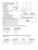
CONNESSIONI / CONNECTIONS / CONNEXIONS
CONEXIONES / VERBINDUNGEN
ATTENZIONE: la scheda è predisposta con il riconoscimento automatico degli ingressi N.C. non utilizzati
(fotocellule, Stop e finecorsa) ad eccezione dell’ingresso COSTA DI SICUREZZA.
WARNING: The control unit is designed with the automatic detection of not used N.C. inputs (photocells,
Stop and Limit switch) except the SAFETY EDGE input.
AVERTISSEMENT: L'armoire est conçue avec la détection automatique des accès N.C. pas utilisés
(photocellules, Stop et fins de course), à l'exception de l'accès BARRE PALPEUSE DE SECURITE.
ATENCIÓN: la tarjeta está predispuesta con el reconocimiento automático de las entradas N.C. no
utilizados, fotocélulas, stop y fin de carrera, con excepción de la entrada COSTA DE SEGURIDAD.
ACHTUNG: Die Steuerung ist mit der automatischen Erkennung der nicht verwendeten N.C. Eingänge,
ausgestattet (Lichtschranken, Stop-und Endschalter) ausgenommen des Sicherheitsleiten Eingangs.
Connettore alimentazione 24V~
24V~ Power connector
Connecteur alimentation 24V~
Conector alimentaci n 24V~
~
ó
Speisungsverbindung 24V
POWER
67411655
2
Elettroserratura /
Electric lock /
Electro-serrure /
Electrocerradura /
Elektroschloss
(12V 15VA max)
REV 01 - 11/2013

INDEX
Sistemi Elettronici
di Apertura Porte e Cancelli
International registered trademark n. 804888
®
English
24
REV 01 - 11/201367411655
DESCRIPTION OF THE COMPONENTS...................................................................................25
GENERAL INFORMATION .........................................................................................................26
QUICK START ............................................................................................................................27
SELFLEARNING WORKING TIME.............................................................................................28
SELECTION OF SETTINGS.......................................................................................................29
RADIO TRANSMITTER SELF LEARNING WITH RECEIVER ON BOARD OF CONTROL
UNIT ...........................................................................................................................................36
DELETE TRANSMITTERS .........................................................................................................36
FUNCTIONING LOGICS.............................................................................................................37
PASSWORD ENTERING MANAGEMENT .................................................................................37
START, STOP, PEDESTRIAN START, ANTENNA, PHOTOCELL CONNECTIONS ..................38
AMPEROMETRIC MANAGEMENT, ELECTRO-LOCK, WARNING LAMP,
EDGE CONNECTIONS ..............................................................................................................39
LIMIT SWITCH, EXTERNAL RECEIVER CONNECTIONS .......................................................40
POWER SUPPLY AND MOTORS CONNECTIONS ...................................................................41
CONNECTION OF BATTERIES .................................................................................................42
TRAFFIC LIGHT CARD CONNECTION .....................................................................................42
ALARMS INDICATIONS, ALARM SIGNALS...............................................................................43
TROUBLE SHOOTING ...............................................................................................................44
WARNING, MAINTENANCE AND WARRANTY .........................................................................44
USER 2 - 24V DG
“ALL IN”

Sistemi Elettronici
di Apertura Porte e Cancelli
International registered trademark n. 804888
®
CN1 = Input/Output connector
CN2 = Limit switch, electro-lock connector
CN3 = Motors connector
CN5 = Battery charger connector
CNA = Receiver module connection
EXP = External module connector
JOLLY = Jolly programmer connector
MF1 - MF2 = Mosfet motor 2
MF3 - MF4 = Mosfet motor 1
POWER = 24V~ power supply connection
PROG = Programming connector
Pr1 = Rectifier jumper
RL1 - RL2 = Relay motor 2
RL3 - RL4 = Relay motor 1
F1 = Fuse 10AT
English
DESCRIPTION OF THE COMPONENTS
13 12 11 10 9 8 7 6 5 4 3 2 1
14 15 16 17 18 19 20
23 24 25 26
+ S -
EXP
CN2
CN3
POWER
CN5
F1
CN1
DISPLAY
UP DOWN OK
CNA
JOLLY
PROG
RL1
RL2
RL3
RL4
MF1
MF2
MF3
MF4
25
67411655
PR1
USER 2 - 24V DG
“ALL IN”
REV 01 - 11/2013

Sistemi Elettronici
di Apertura Porte e Cancelli
International registered trademark n. 804888
®
24V~
30mA
150 W x 2
24Aux (250mA) (Programmable) /
24VL (600mA) (Accessories and Flashing lamp)
24VL (Flashing lamp) 15W max.
-20°C +50°C
10AT
Automatic / Step by step type 1 / Step by step type 2
/ Safety / Dead man / 2 Buttons.
In selflearning in programming phase
Adjustable
Adjustable for single leaf and direction
Adjustable for single leaf and direction
Battery power supply / Total opening / Pedestrian
opening adjustable / Edge (opt.8K2)/
Stop / Limit switch opening and closing / Encoder /
Photcell in opening and closing
Power supply 24Aux (Programmable) /
Motors 24V / 24VL Accessories and Flashing
lamp / Electro-lock 12V 15VA Max
156 x 100 mm
24V Pb 2Ah min.
305 x 225 x 125 mm - Ip55
Battery charger card (code 23101105)
Relay card for traffic light management
(SEM Cod. 23021100)
Programmer JOLLY (code 23105276)
Programmer JOLLY2 (cod.23105277)
Programmer OPEN (code 23105290)
Display BINGO (cod.23101131)
English
GENERAL INFORMATION
The information in this section of the manual are only for technicians or for qualified or authorized
installers.
GENERAL CHARACTERISTICS
The USER 2 24V DG “ALL IN” control unit has been designed to manage one or two low voltage swing gate
operators with or without electronic limit switches.
It is of very small dimensions and besides the possibility to adjust motor speed, amperemetric anti squeezing
sensitivity, leaf delay in closing, pausing time, it is also possible to manage a display, through which it is possible to
control a lot of management functions and the maintenance of the control unit.
TECHNICAL SPECIFICATIONS
Control unit power supply
Absorption in stand by
Max. motor charge
Max. accessories charge
Max. Flash light charge
Environment temperature
Protection fuse
Function logic
Opening/closing time
Time of pause
Thrust
Slow down
Input on connecting terminal
Output on connecting terminal
Board dimensions
Specifications of optional batteries
Specifications of external enclosure
Special accessories
NOTE: The Jolly programmer will be functioning starting from Rev. 35 onwards. You can upgrade the
software of the Jolly and the control units with the OPEN device and the update firmware software.
The herein reported functions are available starting from revision 018.
26
67411655
USER 2 - 24V DG
“ALL IN”
REV 01 - 11/2013

Sistemi Elettronici
di Apertura Porte e Cancelli
International registered trademark n. 804888
®
English
MENU
SEA
SET
MENU
SEA
SET
MENU
SEA
SET
MENU
SEA
SET
MENU
SEA
SET
MENU
SEA
SET
MENU
SEA
SET
MENU
SEA
SET
MENU
SEA
SET
MENU
SEA
SET
MENU
SEA
SET
OK to exit Menu
or press the
button of the next
TX to be stored
Choose the type of
motor with
UP or DOWN
With UP or DOWN choose
ON only if in single
leaf mode
To confirm and return
to the main menu
Skip this step if you are working in double leaf mode
Skip this step if you do not want to program a transmitter
With UP or DOWN
choose
the desired logic
To confirm and return
to main menu
With UP or DOWN
choose a delay for
automatic closing
With UP or DOWN
Choose ON
With UP or DOWN choose ON
to start times learning
At the end of the selflearning
the control unit returns automatically
to the main menu
With
UP or DOWN Choose
ON to start test
To confirm and return to
main menu
Skip this step if a TX has already been stored
UPDOWN
ALL OTHER PARAMETERS HAVE DEFAULT SETTINGS WHICH ARE USEFUL FOR THE 90% OF THE
APPLICATIONS BUT CAN BE HOWEVER SET THROUGH THE SPECIAL MENU. FOR ENTERING INTO THE
SPECIAL MENU PRESS THE UP AND DOWN BUTTONS AT THE SAME TIME FOR 5 S.
QUICK START
OK
Press the
button of the
TX to be
stored
2
3
4
5
6
7
8
To confirm and return
to main menu
To confirm and return
to main menu
OK
OK
OK OK
OK OK
OK OK
OK OK
OK OK
OK OK
UP
UP
UP
UP
UP
UP
UP
OK
To confirm and return
to main menu
Skip this step
if you wna tto work
in half-automatic
logic
PROGRAMMING
BUTTONS
OK
DOWNUP
1
MENU
SEA
SET
MENU
SEA
SET
OK
UP
LANGUAGE
ITALIANO
UP
9
PRESS
BUTTON
STORED
TRANSMITTERS
START
MOTOR
LOGIC
PAUSE TIME
START IN
PAUSE
PROGRAM-
MING
TEST START
ONE SINGLE
LEAF
27
67411655
USER 2 - 24V DG
“ALL IN”
REV 01 - 11/2013

Note1: Put a jumper on SAFETY EDGE contact if not used.
Note2: It is not necessary to put a jumper on the limit switches, photocells and Stop if they
are not used.
1) Check the right operation of the accessories (photocells, buttons etc.).
If necessary set the leaf delay.
2) If necessary adjust the selflearning speed.
3) Switch off power supply (Fig. 1), release the motors (Fig. 2-3) and manually place the leaf on
Fig. 2
Fig. 1
F
F
O
Fig. 7
N
O
BETA
Fig. 5
BETA
A
M2M1
Fig. 8
M2
M1
Fig. 9
M2
M1
Fig. 4
Sistemi Elettronici
di Apertura Porte e Cancelli
International registered trademark n. 804888
®
Fig. 3
FLIPPER
Fig. 6
FLIPPER
English
The control unit is pre-set with the default settings, to start the control unit with the
DEFAULT settings just keep pressed the UP and DOWN buttons at the same time power
supplying the control unit the display shows the message init.
The DEFAULT settings are shown in the Menues table.
WORKING TIMES SELF LEARNING
Operator
released
Operator
locked
Lock
Release
the middle of the stroke (Fig. 4).
Restore the mechanical lock (Fig. 5-6)
4) Power the control unit (Fig.7)
5) Choose the desired motor type; use (default Flipper).
6) Select 8-progRA ING on the display, press OK and then UP and DOWN to start the programming.
Note3: If on single leaf mode set 4-ONE SINGLE LEAF on ON.
Note4: If one or both motors start in opening, switch off power and invert the motor(s) cable starting in opening.
Afterwards repeat the procedure starting from point 4, or activate 19-REUERSE OTOR.
7) Both leaves will start a CLOSE - OPEN - CLOSE cycle automatically (CLOSE M2 - CLOSE M1 - OPEN M1 -
OPEN M2 - CLOSE M2 - CLOSE M1).
End of selflearning.
U
UU
28
67411655
USER 2 - 24V DG
“ALL IN”
REV 01 - 11/2013

English
Sistemi Elettronici
di Apertura Porte e Cancelli
International registered trademark n. 804888
®
SELECTION OF THE SETTINGS
u.001
UP
OK
UP
UP
UP
DOWN
DOWN
DOWN
OK
OK
OK
DOWN
otor
U
UP
F ELD
SVRF
FL PP
Initial system
Software Version
Programming example
MENU
SEA
SET
---
----
---
DISPLAY INPUT STATUS
When the segment
is ON during self-
learning, the input
status is closed or
OFF.
Start
Start
pedestrian
Stop
Limit
Switch
opening
motor 1
Photocell 1
Photocell 2
Edge
Limit
Switch
closing
motor 1
Limit Switch
opening motor 2
Limit Switch
closing motor 2
PedESTR AN Start
EDGE
PHOTO1
PHOTO2
L T SU T(H
OPEN NG 1
U
L T SU T(H
(LOS NG 1
U
L T SU T(H
OPEN NG 2
U
L T SU T(H
(LOS NG 2
U
END
29
67411655
USER 2 - 24V DG
“ALL IN”
The settings of the control unit are made through the UP, DOWN and OK buttons. The UP and DOWN buttons to scroll through the MENUS and
SUBMENUS. By pressing OK you enter from MENU into SUBMENU and confirm the choice.
Moving in the language menu pressing the UP and DOWN buttons at the same time you access the SP MENU for special settings.
Moving in the language menu pressing the OK button for 5 seconds, you enter the CHECK MENU, where you can check the operating status of
all inputs.
MENU
start
stop
0.0u
OK
OK
OK
OK
MENU FUNCTION TABLE CHECK USER 2 24V DG “ALL IN” INPUTS
To access the Menu for input check keep pressed OK for about 5 seconds.
Description
Description
Start test
Stop test
Pedestrian
start test
Safety
edge test
Photocell 1
test
Photocell 2
test
M1 opening
limit switch
test
M1 closing
limit switch
test
M2 opening
limit switch
test
M2 closing
limit switch
test
Batteries’
voltage level
Batteries charge level indicator
The contact must be a N.O. Contact . When activating the related command
on the display SET lights up, the input works.
If SET is always on, check the wirings.
The contact must be a N.C. Contact. If activating the related command on
the display SET lights up, the input works.
If SET is always on, make sure that the contact is a N.C. Contact.
The contact must be a N.C. Contact. If activating the related command on
the display SET lights up, the input works.
If SET is always on, make sure that the contact is a N.C. Contact.
The contact must be a N.C. Contact. If activating the related command on
the display SET lights up, the input works.
If SET is always on, make sure that the contact is a N.C. Contact.
The contact must be a N.C. Contact. If activating the related command on
the display SET lights up, the input works. If SET is always on, make
sure that the contact is a N.C. contact or that the related limit switch is not occupied.
The contact must be a N.C. Contact. If activating the related command on
the display SET lights up, the input works. If SET is always on, make
sure that the contact is a N.C. contact or that the related limit switch is not occupied.
The contact must be a N.C. Contact. If activating the related command on
the display SET lights up, the input works. If SET is always on, make
sure that the contact is a N.C. contact or that the related limit switch is not occupied.
The contact must be a N.C. Contact. If activating the related command on
the display SET lights up, the input works. If SET is always on, make
sure that the contact is a N.C. contact or that the related limit switch is not occupied.
Exit menu
Note: If the Stop, Photocell 1 and Photocell 2 contacts are not bridged in self-learning, they will be deactivated and can be
reactivated through this menu, without repeating times self-learning.
enabled
blo(ked
enabled
blo(ked
enabled
blo(ked
enabled
blo(ked
REV 01 - 11/2013

Sistemi Elettronici
di Apertura Porte e Cancelli
International registered trademark n. 804888
®
MENU
Default
1 - langvage
SET
espanol
engl sk
fran(a s
tal ano
F ELD
SVRF-ALP
BETA
off
1,2,3
off
tal ano
FL PPER
On off
off
off
on
Off on
Off on
off
off
off
English
MENU FUNCTIONS TABLE USER 2 24V DG “ALL IN”
Description
Set value
Italian
English
French
Spanish
3 - otor
U
Surf - Alpha motors
Field motors
Beta motors
Flipper - Ger motors
4 - one s ngle
leaf
In ON activates single
leaf mode
5 - log (
Avto at (
U
open-stop-(lose-stop-open
2 bvttons
safety
Dead an
U
open-stop-(lose-open
Automatic
Step by step type 1
Step by step type 2
Two buttons
Safety
Dead man
Avto at (
U
6 - paVse t e
U
Setting from 1s to 4min.
OFF
(semi-automatic logics)
7 - starT n pavse
In pause start is not acceped
In pause start is accepted
8 - progra ng
U U
9 - test start
Start command
Times learning start
end
Select END and press OK to exit the menu.The menu
deactivates automatically after 2 minutes
FL PPER - ger
stop
start
Start
Stop
External module
start
Ped Start.
U
2 - trans tters
(Lear e ory
UU
External odvle
U
Pedestr an Start
Delete a trans itter
U
Pedestrian Start
Delete single transmitter
Delete transmitter memory
30
67411655
USER 2 - 24V DG
“ALL IN”
REV 01 - 11/2013
dut(k
Dutch

MENU SP
Default
SET
Sistemi Elettronici
di Apertura Porte e Cancelli
International registered trademark n. 804888
®
30 100
30 100
30 100
10 100
10 100
75
70
1 - OTOR SPEED 1 *
U
30 100
75
30
50
Off 6
3
3
Off 20
70
10 100
10 100
70
70
Off
Off
Off
5 100
Off
5 100
30
30
English
UPDOWN
PRESS AT THE SAME TIME FOR 5 SECONDS TO ENTER OR TO EXIT THE SPECIAL MENU
SPECIAL MENU FUNCTIONS TABLE USER 2 24V DG
To ENTER the Special Menu keep pressed UP and DOWN at the same time for 5 seconds.
To EXIT the Special Menu pressed END or keep pressed UP and DOWN at the same time for 5 seconds.
“ALL IN”
Description
Set Value
2 - OTOR SpEED 2 *
U
Setting from 30 to 100
Setting from 30 to 100
Setting from 30 to 100
Setting from 30 to 100
3 - sloudoun speed *
4 - learn ng speed *
6 - leaf delay n (los ng
5 - leaf delay n open ng
Setting from OFF to
6 seconds
Setting from OFF to
20 seconds
7 - open ng torq 1 *
8 - (los ng torq 1 *
Opening torque M1 and
amperometric sensitivity
Note: By increasing the
torque the sensitivity
decreases
Closing torque M1 and
amperometric sensitivity
Note: By increasing the
torque the sensitivity
decreases
Opening torque M2 and
amperometric sensitivity
Note: By increasing the
torque the sensitivity
decreases
Closing torque M2 and
amperometric sensitivity
Note: By increasing the
torque the sensitivity
decreases
9 - open ng torq 2 *
10 - (los ng torq 2 *
11 - Pvshouer
Off
Only (los ng
12 - pvsk ng stroke
Off 3
Open ng and (los ng
Only open ng
Disabled
Opening an closing
Opening only
Closing only
From OFF to 3 seconds
14 - (los ng sloudoun 1
13 - open ng sloudoun 1
Disabled
Setting from 5 to 100
Disabled
Setting from 5 to 100
31
67411655
USER 2 - 24V DG
“ALL IN”
REV 01 - 11/2013

Sistemi Elettronici
di Apertura Porte e Cancelli
International registered trademark n. 804888
®
MENU SP
Default
SET
Off
5 100
Off
5 100
30
30
1 240
100 10e4
0 100
0 10e4
75
10e4
0
= start
Off
= start
Off on
Off
20 100
100
1 240
bvzzer
Off
Buzzer
0.0 5.0
Off
Off
On
Off
20 - en(oder
On Off
Off
28 - t er
U
off
off
English
16 - (los ng sloudoun 2
15 - open ng sloudoun 2
Disabled
Setting from 5 to 100
Disabled
Setting from 5 to 100
17 - preflasx ng
Only (los ng
Pre-flashing active only
before closing
Pre-flashing time
Normal
18 - flasx ng l gxt
Nor al
U
L gxt
aluays
Control lamp
Always ON
Nor al
U
19 - reuerse otor
U
In ON enables the
Encoder, in OFF
it's disabled
Synchronized right motor
Synchronized left motor
21 - (ourtesy l gxt
N (y(le
Disabled
Courtesy light setting
from 1s to 4min.
Courtesy light in cycle
N (y(le
22 - traff ( l gxt
reseruat on
When setting this function
the pedestrian input will be
activated to work on the
auxiliary board SEM
(traffic light management).
23 - pedestr an open ng
24 - pedestr an PAUSE
Setting from 20 to 100
Pause in pedestrian
opening same as in
total opening
Disabled
Setting from 1s to 4 min.
25 - a((elerat on
26 - a ntenan(e (y(les
U
27 - perfor ed (y(les
U
Acceleration ramp
Setting from 100 to
100000
Reports the executed
cycles. Keep pressed OK
to reset the cycles
ON PXOTO2
ON PEDESTR AN ENTRY
Disabled
Timer function active
on photocell 2
Timer function active on
pedestrian input
Description
Set Value
32
67411655
USER 2 - 24V DG
“ALL IN”
REV 01 - 11/2013

MENU SP
Default
SET
Sistemi Elettronici
di Apertura Porte e Cancelli
International registered trademark n. 804888
®
8x2
English
Description
Set Value
Nor al
U
29 - edge
Edge is active and
protected by a 8k2 resistor
Normal N.C. contact
Nor al
U
stop
30 - PXOTO1
(LOS NG
Stop AND (LOSE
(LOSE
PAUSE RELOAD
OPEN NG
Photocell active in
closing
Photocell active in
opening
The photocell gives a
command to close during
opening, pause and
closing
The photocell charging the
pausing time
Photocell active before
opening
The photocell stops in closing
and closes when released
(LOS NG
stop
31 - PXOTO2
(LOS NG
Stop AND (LOSE
(LOSE
PAUSE RELOAD
OPEN NG
Photocell active in
closing
Photocell active in
opening
The photocell gives a
command to close during
opening, pause and
closing
The photocell charging the
pausing time
Photocell active before
opening
The photocell stops in closing
and closes when released
OPEN NG
33
67411655
USER 2 - 24V DG
“ALL IN”
If the photocell is occupied
during opening, pause or
closing, the gate reopens
completely and closes
without observing the
pause time.
Delay pause ti e
u
If the photocell is occupied
during opening, pause or
closing, the gate reopens
completely and closes
without observing the
pause time.
Delay pause ti e
u
REV 01 - 11/2013

Sistemi Elettronici
di Apertura Porte e Cancelli
International registered trademark n. 804888
®
41 - fototest
Foto1-2
off
off
Off
0 15
Off
1 100
Off
On
1 10
6
MENU SP
Default
SET
off 8 off
English
Description
Set Value
33 - POS T ON RE(OUERY
34 - OTOR RELEASE *
U
Regulates the recovery of
the motor inertia
Disabled
Setting from 1 to 100
35 - PER OD (AL pvshouer
Allows the repetition of the
Pushover functionat a
distance of time adjustable
from 0 to 8 hours at hourly
intervals
Off
36 - ant ntrvs on
ONLY (LOS NG
ONLY OPEN NG
OPEN NG AND (LOS NG
Only on limit switch in opening
Only on limit switch in closing
On limit switches in closing
and in opening
Disabled
1
Off 5
38 - lock
37 - LOCK T E
U
Sets the lock release
time from 0 to 5 s
ONLY (LOS NG
ONLY OPEN NG
OPEN NG AND (LOS NG
Active only before opening
Active before opening
and closing
Active only before closing
OPEN NG
40 - d agnost (S
39 - FLASX NG L GXT AND
t er
U
Shows last event
(See alarms table)
The flashing light remains
ON with active timer and
open gate
The flashing light remains
OFF with the active timer
and open gate
PXOTO1
PXOTO2
PXOTO1-2
Auto-test active only on
Photo1
Auto-test active only on
Photo2
Auto-test active on
Photo1 and Photo2
34
67411655
USER 2 - 24V DG
“ALL IN”
32 - 24u avx
N (Y(LE
N pavsE
fototest
N (Y(lE AND fototest
OPEN NG
(LOS NG
ALUAYS
24Vaux output power
supplied only during opening
24Vaux output power
supplied only during closing
24Vaux output power
supplied only during pause
24Vaux output for
connection of photocell
TX to autotest
24V output active only
during cycle
24V output only during cycle
with fototest function active
ALUAYS
24Vaux output always
power supplied
REV 01 - 11/2013

MENU SP
Default
SET
Sistemi Elettronici
di Apertura Porte e Cancelli
International registered trademark n. 804888
®
51 - passuord
---- ----
Off
off
Off
10 99
10 99
off
Off
off
Off
10 99
10 99
off
English
Description
Set Value
46 - OPEN NG SENS T U TY
otor 1 *
U
47 - (LOS NG SENS T U TY
otor 1 *
U
Adjusts the revesing
sensitivity on motor 1 in
opening. Note: Only with
Encoder On active.
Adjusts the revesing
sensitivity on motor 1 in
closing. Note: Only with
Encoder On active.
Adjusts the revesing
sensitivity on motor 2 in
opening. Note: Only with
Encoder On active.
Adjusts the revesing
sensitivity on motor 2 in
closing. Note: Only with
Encoder On active.
Disabled
Disabled
Disabled
Disabled
49 - (LOS NG SENS T U TY
otor 2 *
U
END
Allows the entering of a
password which blocs the
modification of the control unit
parameters (see page 37)
Select END and press OK to exit the special menu.
The special menu deactivates automatically after 20 minutes.
Note 1: The * indicates that the default value may change depending on the selected motor type.
Note 2: After initialization the parameters "motor type" and "limit switch type" remain son the value chosen in
the setup program.
48 - OPEN NG SENS T U TY
otor 2 *
U
35
67411655
Avto at (
U
ONLY (LOS NG
Avto at (
U
50 - sELE(T L T SU T(K
U
ONLY OPEN NG
Limit switch in automatic
recognition
Only limit switch in
opening present
Only limit switch in
closing present
USER 2 - 24V DG
“ALL IN”
0
0
0 100
0 100
0
0
0 100
0 100
Adjusts the amperometric
tolerance in relation to the
detected stop in closing
Adjust the amperometric
tolerance in relation to the
detected stop in opening
42 -OPEN NG TOLERAN(E
otor 1
U
43 - (LOS NG TOLERAN(E
otor 1
U
44 -OPEN NG TOLERAN(E
otor 2
U
45 - (LOS NG TOLERAN(E
otor 2
U
Adjusts the amperometric
tolerance in relation to the
detected stop in closing
Adjust the amperometric
tolerance in relation to the
detected stop in opening
REV 01 - 11/2013

Sistemi Elettronici
di Apertura Porte e Cancelli
International registered trademark n. 804888
®
Sistemi Elettronici
di Apertura Porte e Cancelli
International registered trademark n. 804888
®
English
RADIO TRANSMITTER SELF LEARNING
WITH RECEIVER ON BOARD OF CONTROL UNIT
1 2 3 4
0
1
2
3
4
5
6
7
8
9
10
11
12
13
14
15
16
17
18
19
20
Transmitter
button
Memory
location
Serial number Customer
TABLE
EXAMPLE
!!
WARNING: Make the radio transmitters programming before you connect the antenna and insert the receiver into the special
CMR connector (if available) with turned off control unit. (The control unit automatically recognizes if the receiver is a RF, RF Roll, RF
Roll Plus or RF UNI module).
With RF Roll or RF Roll Plus module it will be possible to use only Coccinella Roll or Coccinella Roll Plus radio transmitters. or Smart
Dual Roll or Smart Dual Roll Plus.
With the RF UNI module it will be possible to use both the transmitters of the Roll Plus series and those with fixed code. The first
memorized transmitter determines the type of the remaining radio transmitters.
Select through the display trans itters and press OK, now select with the UP and DOWN buttons, the command to which you want to
associate the button (it is possible to associate max. 2 commands) and press OK to confirm the choice, now press the button of the radio
transmitter which you want to associate. If the storage is successful, the display will show STORED .
If the receiver is a Rolling Code, press twice the button of the radio transmitter that you want to program to memorize the first TX.
In the trans itters MENU it is possible to select Start (to associate a Start command), pedestrian start (Pedestrian Start ), external
odvle (For the activation of a contact on the EXP output), StoP (To associate the STOP command to the TX), dELete a trans itter (To
delet the single transmitter only if it is a Rolling Code Plus), (lear e ory (To delete all TX).
Notes:
- Enter radio transmitters learning only when the working cycle stops and the gate is closed.
- If the radio transmitters are Rolling Code it’s possible to memorize up to 800 codes (buttons).
- If the radio transmitters are with fixed code it will be possible to memorize up to max. 30 codes (buttons).
- You can store max. 2 of the available 4 functions. If the control unit receives a code which was already associated to another function it will be
updated with the new function.
DELETE TRANSMITTERS FROM THE RECEIVER
With modules different from RF UNI, it will be possible to delete only the entire memory of the receiver.
Proceed as follows: select from the menu trans itters: (lear e ory and hold the OK button until the display shows the message Ok.
With the RF UNI module, it will be possible to also delete the single button of the transmitter.
It can be done in two ways:
1) If you have the transmitter, or if you are using transmitters with fixed code, the cancellation can be executed by simply retransmitting the code.
Ex. Button 1 of the transmitter memorized as START; access the menu trans itters press OK, select STaRT, press OK.
Send a STaRT command from the transmitter and on the display will show deleted.
At this point the single button results deleted.
2) If you do not have a transmitter, or you are using a Roll Plus transmitter, you can delete the transmitter selecting the serial number of the
transmitter to be deleted.
Procede as follows: Access the menu trans itters, press OK, select Delete a trans itter, press OK, choose the memory location to be
deleted through the UP and DOWN buttons, press OK, check on the display if the serial number of the transmitter to be deleted is the right one,
press OK, on the display shows SvRE?, if the transmitter to be deleted is the right one press OK and OK will appear to confirm the cancellation,
otherwise press the DOWN button to return to the menu trans itters.
Note: When using Roll Plus transmitters, it is recommended to record on a table similar to the below example, the serial number associateding
it to the memory location where it was stored.
U
U
U
U
U
U
U U
U
UU
U
U
36
67411655
USER 2 - 24V DG
“ALL IN”
REV 01 - 11/2013

Sistemi Elettronici
di Apertura Porte e Cancelli
International registered trademark n. 804888
®
English
FUNCTION LOGIC
AUTOMATIC LOGIC
A start impulse opens the gate. A second impluse during the opening will not be accepted.
A start impulse during closing reverses the movement.
SECURITY LOGIC
A start impulse opens the gate. A second impulse during opening reverses the movement.
A start impulse during closing reverses the movement.
STEP BY STEP TYPE 1 LOGIC
The start impulse follows the OPEN-STOP-CLOSE-STOP-OPEN logic.
STEP BY STEP TYPE 2 LOGIC
The start impulse follows the OPEN-STOP-CLOSE -OPEN logic.
DEAD MAN LOGIC
The gate opens as long as the START button of opening is pressed; releasing it the gate stops. The gate closes as long as the
button connected to the PEDESTRIAN START is pressed; releasing it the gate stops. To execute complete opening and/or
closing cycles the related pushbuttons must be constantly pressed.
2 PUSHBUTTONS LOGIC
One start opens, one pedestrian start closes. In opening the closing will not be accepted. In closing a start command reopens, a
pedestrian start command (closes) will be ignored.
NOTE 1: To have the automatic closing it is necessary to set a pause time, otherwise all the logic will be semi-automatic.
NOTE2: It is possible to choose, whether to accept or not, the start in pause, selecting in the MENU the item Startin
pavse and choosing ON or OFF. By default, the parameter is OFF.
PASSWORD ENTERING MANAGEMENT
With a new control unit all menus can be displayed and set and the password will be disabled.
Selecting one of the Menus and keeping UP and DOWN pressed at the same time for 5 seconds, you will access the SP Menu
containing the Passuord Submenu.
Pressing OK in the Passuord Menu, you will proceed with the entering of the numeric code of the 4-digit PASSWORD.
Use UP and DOWN to increase or decrease the number, press OK to confirm it and you will pass automatically to the entering of
the next number. Pressing OK after the last entered number the word SvRE? appears, confirm the activation of the PASSWORD
and the message Ok appears, pressing UP or DOWN instead you can cancel the operation and NO OPERATION will appear on the
display.
Once entered the PASSWORD, it will be definitively activated, once the display switch off timeout has expired, or by turning off
and on again the control unit. Once the PASSWORD has been activated, the menus of the display can be only displayed but not
set. To unlock them you must enter the correct PASSWORD in the Passuord menu, if the password is wrong the message ERRor
will appear.
At this point, if the password has been entered correctly, the menus will be unlocked and it will be possible to change the
parameters of the control unit again.
If the control unit has been unlocked through Passuord Menu, it is possible to enter a new and different password, using the
same entering process as for the first one; at this point, the old password will no longer be valid.
If the password has been forgotten, the only way to unlock the control unit is to contact the SEA technical assistance, which will
assess whether to provide the procedure to unlock the control unit or not.
Note: The password cannot be set through the Jolly or Jolly 2 terminal.
37
67411655
USER 2 - 24V DG
“ALL IN”
REV 01 - 11/2013

Sistemi Elettronici
di Apertura Porte e Cancelli
International registered trademark n. 804888
®
TIMER
Common
English
PEDESTRIAN START (N.O.) The pedestrian start can be connected between
the clamps 2 and 4 of the CN1 terminal .
This input allows a partial opening the opening space can be set through the on-
board display or through the JOLLY device.
Note1: The contact for partial opening is a N.O. Contact (Normally open).
Note2:In 2 BUTTONS logic it is necessary to keep pressed the Start Ped. to re-
close the automation.
Note3: In dead man logic this button executes the re-closing if you keep it
pressed.
Note4: When closed during pause, the gate will reclose only after this input has
been reopened.
TIMER activation: This input can be transformed into TIMER (See TIMER).
START (N.O.) The
An impulse given to this contact opens and closes the automation depending onthe selected logic it can be given by a key switch, a keypad,
etc. To connect the other devices refer to the related instructions leaflets. (ie. loop detectors and proximity switches).
Note1: In DEAD MAN logic it is necessary to keep pressed the Start for the opening of the automation.
Note2:
START is connected between the clamps 2 and 3 of the CN 1 terminal.
In 2 BUTTONS logic this button performs the opening.
Timer activation: it is possible to connect a timer on the start only in auto logic with time of pause different than DISB and with START IN
PAUSE function OFF.
STOP (N.C.) The STOP is connected between the clamps 2 and 5 of the CN1
terminal . The pressure on this button immediately stops the motor in any
condition/position. A start command is needed to re-start the movement.
After a stop the motor always re-starts in closing.
Can be activated through on-board display or through the Jolly programmer. In both cases it’s a N.O. contact which provoques the opening of the
automation keeping it open until it is activated. When it’s released, the gate attends the set pausing time and executes the reclosing. The TIMER
command can be activated on the inputs FOTO2, START PEDESTRIAN.
Note1: When activated on the pedestrian entry, the pedestrian will be disabled also on the radio transmitter.
Note2: In case of intervention of a security device during the timer (Stop, Ammeter, Edge), to restore the movement it will be necessary to give a
start impulse.
Note3: In case of no power supply with open gate and active Timer the control unit will restore its use, otherwise if during restore of the power
supply the TIMER is not activated it will be necessary to give a start impulse for the reclosing.
Common
Common
Photocell 1
Photocell 2
START - STOP - PEDESTRIAN START - ANTENNA -
PHOTOCELL
Photocell 1 and Photocell 2 Connections
+ = 24VL COM = 0V PH1 = Photocell contact 1 PH2 = Photocell contact 2
Note1: For the autotest connect in the menu 32-24uavk the TX to the 24VAux clamp and activate
the Autotest function. Note2: The in (y(le and fototest function will keep the photocells
OFF while the gate is closed, thus saving energy. Note3: On the 41-fototest menu you can
also activate the self-test even on the single photocell. The standard setting of the photocell 1 is
FOTO CLOSE and the one of the photocell 2 is FOTO OPEN. The photocell 2 can be set also as
TIMER (see TIMER function). The selftest can be applied also on single photocell.
CN1
12
3
4
5
678
2
1
3
4
5
6
6
7
6
8
Antenna
Start
Start ped.
Stop
RX1
RX2
TX1
TX2
CN1
24VL accessories
Options 24Aux can be set with on-board Display or with Jolly device.
It is possible to chose when having tension on the 24Aux output. The options are:
always, only during opening, only during cycle, only before opening or only during
pause. When using control units with batteries and / or solar panels, we
recommend connecting the accessories which are not used when operator
stands still (e.g. photocells) to a 24VAux output, setting the option “in (y(le”.
With this setting you can save energy by lowering power consumption in stand-by,
increasing the autonomy of the system.
OPTIONS ON FOTO1 and FOTO2 adjustable on on- board display or with JOLLY terminal.
FOTO CLOSE activation ((losing): if occupied, reverses the movement in closing, during pause it
prevent the closing.
Activation repeat pause (pavse RELOAD): If occupied, during pause it recharges the timer of pause. In
closing it reverses the movement.
FOTO OPEN activation (oPEning): If activated the photocell blocks the movement as long as it’s busy,
when released the opening continues.
FOTO PARK activation (stop and (lose) : in opening it is not active; in pause are activated it
commands the closing when released, otherwise it’s not active; in closing it stops the movement as long
as it is busy, when released the closing continues.
FOTO STOP activation (STOP): When activated before the opening the photocell blocks the automation
11 12
12
11
12
11
12
11
12
11
38
67411655
USER 2 - 24V DG
“ALL IN”
as long as it is busy, during the opening it will be ignored. In closing the intervention of the photocell
causes the reopening.
Activation PHOTO CLOSE IMMEDIATELY ((lose): The photocell stops the gate as long as it is
occupied in both opening and closing, when released it gives a closing command (Closing one
second after release of the photocell ).
delay pause ti e activation: If the photocell is occupied during opening, pause or closing, the
gate reopens completely and closes without observing the pause time.
u
REV 01 - 11/2013

Sistemi Elettronici
di Apertura Porte e Cancelli
International registered trademark n. 804888
®
Electro-lock exit
An electro-lock of 12V 15VA max can be connected. It is
possible to disactivate the electroc-lock if not used. This
operation allows to save energy of the control unit. The
release of the electro-lock can be timed’ from 0 to 5 s.
ELECTRO- LOCK
WARNING LAMP
Flashing Lamp 24VL 15W (Warning lamp ) /
24VL 4W Led
The warning lamp advises that the automatic gate is in
movement performing 1 flash /second in opening and 2
flashes / second in closing. Instead it remains turned on fix
during pause.
To connect it, connect the wires of the warning lamp as
shown in the figure. Note: It is recommended to use the
flash 24V Led.
Pre-flashing form 0 to 5 seconds can be activated before
operator start or only before closing.
Furthermore from the flashing lamp it is possible to verify
some alarm signals. See alarms indications.
It is possible to set this exit with fixed flashing also when the
gate is not moving or it is possible to change this exit into
control lamp. In such case all the indications of alarm
remain on the warning lamp as long as they are active.
English
AMPEROMETRIC DEVICE FOR ELECTROMECHANICAL OPERATORS
This control unit comes with an obstacle detection system working only on electromechanical operators
allowing to have the reversing on obstacles and the automatic detection of the stops.
The sensitivity is adjustable for single leaf and single opening and closing direction through the torque
parameter.
ATTENTION: The first operation after power failure, will be executed with the set speed to search the
mechanical stops limit.
AMPEROMETRIC MANAGEMENT
ELECTRO- LOCK AND WARNING LAMP - EDGE
12
3
4
5
6
789
10
1112
13
CN1
12
13
FL(-)
24VL
Common
9
11
Safety edge
SAFETY EDGE
It is possible to connect an active safety edge on the
terminal CN1. If this device is pressed it opens the contact
causing a partial inversion of the movement both in opening
and in closing. If not used bridge the contacts 9 and 11 of
CN1. Note: contact N.C.
14 15 16 17 18 19 20
CN2
20
19
39
67411655
USER 2 - 24V DG
“ALL IN”
REV 01 - 11/2013

Sistemi Elettronici
di Apertura Porte e Cancelli
International registered trademark n. 804888
®
LIMIT SWITCH
English
Opening
Limit Switch M2
Closing
Limit Switch M2
Opening
Limit Switch M1
Closing
Limit Switch M1
EXTERNAL RECEIVER
Example: Connection of a
radio receiver
For the connection of the
receiver refer to the relative
instructions manual.
N.C.
N.C.
N.C.
N.C.
Limit switch
If not connected they don't have to be bridged.
For the limit switch function the presence of the limit switches in
both closing and opening is necessary.
It is possible to activate the function anti-intrusion. Limit switch,
that if released, forces the motor to re-close.
For the right function of the limit switches there
must be a corrsipondence between the direction of
movement of the motors and the respective occupied limit
switches.
Com = Common
C = Contact
Available from Rev.1 17
!!
Common
24VL
14 15 16 17 18 19 20
CN2
12
11
12
3
4
5
6
789
10
1112
13
CN1
2
3
4
40
67411655
Note: In the menu 50 you
can choose whether to
work only with the limit
switch in opening, only with
those in closing, with none
of the limit switches or with
all 4 of them.
USER 2 - 24V DG
“ALL IN”
18
14
18
15
18
16
18
17
REV 01 - 11/2013

M1
BETA
ALPHA STD
Sistemi Elettronici
di Apertura Porte e Cancelli
International registered trademark n. 804888
®
GN
FLIPPER
M2
ALPHA STD
BETA
GN
115V~
or
230V~
P
SURF
SURF
FLIPPER
CN3
P
English
POWER SUPPLY - MOTORS
3,6 A delayed fuse on 230V ~ power supply .
6,3A delayed fuse on 115V ~ power supply.
Motor 2
Output for Motor 2
connection
M+ = OPEN/CLOSED
M- = CLOSED/OPEN
Motor 1
Output for Motor 1
connection
M+ = OPEN/CLOSED
M- = CLOSED/OPEN
Power input
Input for the connection of the electric power.
P = PHASE - LIVE
N = NEUTRAL
G = GROUND
NOTICE: for the connection to the electric
power see the law in force.
23 24
25
26
41
67411655
USER 2 - 24V DG
“ALL IN”
26
25
26
25
26
25
24
23
24
23
24
23
REV 01 - 11/2013
/