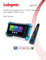
IP/CCTV Tester Manual
V2.10
CAMERA WIZARD II
TESTS
IP CAMERA TESTS
IP address scan: Scan IP cameras and network device’s for IP address
Link monitor: Displays all IP addresses for a given gateway
Port flicker: Blink a port’s link LED to identify cable location
PING test: Search for IP address to verify connectivity
POE tester: Displays PoE voltage
CAT5/6 cable tester: Performs a pairs test on CAT5/6 cables
Note: IP video image is not displayed on LCD
CCTV CAMERA TESTS
Video image display: 3.5" LCD with 960x240 resolution
Video signal level meter: Display peak to peak value
PTZ camera controls for numerous camera types
RS485/RS422 input and data logging
3.5mm audio input
Built in speaker
Color bar signal generator
BNC input with 3' M-to-M BNC pigtail
POWER AND ACCESSORIES
Up to 11 hour battery life
4 hour recharge time
12VDC 1A output to power camera with 3’ pigtail
5VDC 2A AC adaptor powers and charges tester
Li-ion 3.7V 3000mAh rechargeable battery (replacement battery available)
Carrying case included
Contents
1Safety information ................................................................................................................................. 1
2Introduction ............................................................................................................................................ 2
2.1 General ........................................................................................................................................ 2
2.2 Features ....................................................................................................................................... 2
2.3 Function ...................................................................................................................................... 3
2.3.1 Video signal testing (CCTV) ........................................................................................ 3
2.3.2 Video signal level test (CCTV) ..................................................................................... 3
2.3.3 PTZ controller (CCTV) ................................................................................................. 3
2.3.4 Enhanced Color bar generator (CCTV) ........................................................................ 3
2.3.5 DC12V 1A output power (CCTV) ................................................................................ 3
2.3.6 Audio testing (CCTV) ................................................................................................... 3
2.3.7 Cable tester (CCTV AND IP) ....................................................................................... 3
2.3.8 RS485 Data Test (CCYV)............................................................................................. 4
2.3.9 PTZ address scanning (CCTV) ..................................................................................... 4
2.3.10 Image magnificationCCTV) ................................................................................... 4
2.3.11 Video snapshot (CCTV).............................................................................................. 4
2.3.12 Video record (CCTV) ................................................................................................. 4
2.3.13 Video playback (CCTV) ............................................................................................. 4
2.3.14 Port flicker (IP) ........................................................................................................... 4
2.3.15 IP address scan (IP) ..................................................................................................... 4
2.3.16 Link monitor (IP) ........................................................................................................ 4
2.3.17 PING test (IP) .............................................................................................................. 4
2.3.18 POE tester (IP) ............................................................................................................ 4
2.3.29 LED flashlight ............................................................................................................. 5
2.3.20 F1F2 User-defined shortcut keys ............................................................................ 5
2.4 Accessories.................................................................................................................................. 5
2.5 Front Panel .................................................................................................................................. 6
3Operation ............................................................................................................................................. 10
3.1 Installing the Battery ................................................................................................................. 10
3.2 Quick tester connection for CCTV use ..................................................................................... 11
3.3 OSD Menu ................................................................................................................................ 11
3.3.1 PTZ controller ............................................................................................................. 12
3.3.2 Color-bar generator ..................................................................................................... 15
3.3.3 Video in level .............................................................................................................. 15
3.3.4 PTZ address search ..................................................................................................... 16
3.3.5 10x zoom image display and Video out ...................................................................... 17
3.3.6 Photograph .................................................................................................................. 1 7
3.3.7 Video record ................................................................................................................ 18
3.3.8 Record playback .......................................................................................................... 18
3.3.9 PING Test .................................................................................................................... 19
3.3.10 Cable tester ................................................................................................................ 19
3.3.11 Port flicker ................................................................................................................. 20
3.3.12 Link monitor .............................................................................................................. 20
3.3.13 IP address scan .......................................................................................................... 21
3.3.14 PoE tester .................................................................................................................. 21
3.3.15 Data monitor .............................................................................................................. 22
3.3.16 Time setup ................................................................................................................. 2 3
3.3.17 Device (tester) setup .................................................................................................. 23
3.3.18 USB ........................................................................................................................... 24
3.4 DC12V 1A power output .......................................................................................................... 24
3.5 Audio input test ......................................................................................................................... 25
3.6 LED flashlight ........................................................................................................................... 25
4Specifications ....................................................................................................................................... 25
4.1 General Specifications .............................................................................................................. 25
IP/CCTV Tester User’s Manual
1
1Safety information
Notice
The tester is intended to be used in a responsible and safe manner and not in areas where the use
of electrical instruments could be dangerous (hospitals, gas stations etc.).
The tester should be kept dry. Dust and liquid should be avoided.
Like any instrument, treat carefully. Avoid dropping .
Don’t leave the tester alone when charging. If the battery is hot, the tester should be
disconnected from the electric source. The tester should not be charged for more than 8 hours.
Don’t use the tester where the humidity is high. Once the tester is damp, power off immediately
and move it away from other connected cables.
The tester should not be used in the environment with the flammable gas.
Do not disassemble the instrument, since no component inside can be repaired by the user. If the
disassembly is necessary, please contact the factory.
The instrument should not be used in an environment with strong electromagnetic interference.
Do not touch the tester with wet hands.
Do not use detergent to clean. Instead, use a dry cloth. If the dirt is not easy to remove, a soft
cloth with water or neutral detergent can be used.
Limited Warranty
Byte Brothers test equipment warrants to the original consumer that this product is in good
working order for a period of one year from the date of purchase. During the period this product
will be repaired or replaced without charge for either parts or labor unless this unit has been
damaged by the user. Repair or replacement as provided under this warranty is the exclusive
remedy of the purchaser.
IP/CCTV Tester User’s Manual
2
2.Introduction
2.1 General
The Camera Wizard II IP/CCTV tester is designed for the installation and maintenance of IP and CCTV
cameras and devices. CCTV tests: Video display, PTZ control, DC12V output power, audio test, color
generator, RS485 data decoding, picture and video recording, and image magnification. IP camera
tests: IP address scanning, PING testing, Link monitor, POE measurement, Port flicker and CAT5/6
cable testing. Note: The color LCD screen will only display CCTV images (not IP images).
2.2 Features
High definition 3.5”TFT-LCD color display, 480(RGB)x320 (CCTV only)
Built-in LED flashlight
User-defined shortcut keysF1 and F2
Support for both NTSC/PAL video formats
10x zoom feature to magnify the video image (CCTV only)
Record and playback CCTV snapshots and videos using a micro SD card
(removable).
IP address scan to determine an IP camera’s IP address
PING an IP address to verify the connectivity of IP cameras or network devices
POE measurement to test the PoE switch’s voltage to the IP camera
Port Flicker blinks a switch port’s link LED. Perfect for tracing cable locations.
Cable testing jack to test the pairs of a CAT5/6 cable.
Link monitor to display IP address usage on the network.
PTZ address scan to determine the address of a CCTV camera.
RS232/RS485/RS422 communication link to drive the PTZ unit.
PTZ testing for cameras so equipped. Driver supports more than thirty protocols.
DC12V 1000ma power output to temporarily power CCTV camera during test.
Audio input jack to test audio signals
Lithium Ion Polymer Battery . This power-efficient battery can last 11 hours during
normal use. Charging time is 4 -5 hours.
IP/CCTV Tester User’s Manual
3
2.3 Functions
2.3.1 Video signal display
Display the CCTV image on the built-in high definition 3.5”LCD-TFT 480RGBx320
full-view display color screen. Supports PAL/NTSC. The LCD screen brightness/contrast/color and
saturation are adjustable. Note: The color LCD screen will only display CCTV images (not IP images)
2.3.2 Video signal level test
Test the CCTV video signal strength (attenuation). Longer video cables cause the image to dim and
reduces the image’s dynamic range. If the video signal is too strong, it will cause a virtual shadow and
reduce the sharpness of the image. The level test also displays the video level value and, if out of range,
a notice will be displayed on the screen.
2.3.3 PTZ controller
While displaying the CCTV image, this feature pans, tilts and zooms the PTZ base, if the camera is so
equipped. The tester emulates many common PTZ protocols and sets up the controlling parameters like
protocol, communication port, baud rate, PTZ ID and pan/tilt speed. These parameters can be stored and
recalled (“preset” positions).
2.3.4 Enhanced Color bar generator
The video generator is a PAL/NTSC multi-system color bar video generator used to test the security
system’s video monitors. With the video generator, you can judge whether the color is different because
of the transmission loss or interference.
2.3.5 DC12V 1000ma output power
Power the CCTV camera with the DC12V (1A) power output from the tester. This is helpful during
installation when camera power might not be available.
2.3.6 Audio testing
Test the audio input from pickup devices. Connect the tester and pickup device with the audio cable.
2.3.7 Cable tester
Test a CAT5/6 cable’s pinouts by using the cable test jack (UTP/SCAN) and the included remote.
Connect the CAT5/6 cable to the cable test jack. Connect the remote on the far end of the cable. The
cable test results show the pin-to-pin termination of the wires.
IP/CCTV Tester User’s Manual
4
2.3.8 RS485 data test
Analyze the data coming from a RS485/RS422 device. The data is displayed in hexadecimal format.
2.3.9 PTZ address scanning
Discover the address of the PTZ camera.
2.3.10 Image magnification10xZoom
Set image 10x zoom, can view and display the details by 1x2x3x4x5x6x – 10X zoom in the
monitor and tester.
2.3.11 Video snapshot
Capture the video image and save the current video frames as a JPEG file
2.3.12 Video record
Record and save the current video on a SD card.
2.3.13 Video playback
Playback the video images that have been saved on the SD card. The file directory name that is created
is based on the date setting of the tester.
2.3.14 Port flicker
Use this feature to blink the link LED on a switch port. Perfect for tracing the location of a cable that is
terminated into a live switch port.
2.3.15 IP address scan
Quickly determine a camera’s IP address with the IP address scan feature. The IP address scan steps
through every possible address in the network’s subnet to determine the IP camera’s address. The
subnet is entered into the tester as part of making the tester a part of the same network .
2.3.16 Link monitor
The link monitor lists the IP address of all network devices that it discovers in its own subnet. This is
useful in making sure there is not a conflict with new IP addresses that are added to an existing network.
2.3.17 PING test
PINGING is a very popular network debugging tool. First, configure the tester with its own IP address
to make it a network device, then you use the tester to contact (ping) other Ethernet devices.
2.3.18 POE tester
Detect and display the existence of PoE power. When PoE power is present, the tester will measure and
IP/CCTV Tester User’s Manual
5
display the voltage that the PoE switch or injector is supplying to the IP camera.
2.3.19 LED flashlight
Light up the workspace with the ultrabright LED on the front of the tester.
2.3.20 F1, F2 User-defined shortcut keys
The user-defined shortcut keys can be setup to do your most popular tests.
2.4 Accessories
1). IP/CCTV camera and device tester
2). Power Supply: DC5V 1.21.5Awith included USB cable
3). Cable test remote adaptor
4). Lithium Ion Polymer Battery3.7V DC 3000mAh
5). BNC cable
6). RS485 cable
7). CCTV camera power cable
8). Audio cable
9). Safety cord
10). Tool bag
11). Instruction Manual
2
2
.5 Front Pa
n
IP/C
C
n
el
C
TV Tester Us
e
6
r’s Manual
1
2
3
4
5
6
7
8
9
10
11
12
13
14
15
16
17
18
19
20
IP/C
C
OSD menu
The charge indi
c
is complete, the
The data-trans
The data-recept
The power indi
c
Set key, press it
Press more than
menu display
Confirm/Open :
Return/Close :
R
decrease the ap
e
Upward: Select
PTZ upward
User-defined ke
LED Lamp
RightwardEnt
e
Add the value o
Number not use
Downward: Sel
e
Tilt the PTZ do
w
Leftward: Enter
Reduce the val
u
Record CCTV
v
Snapshotcapt
u
10xzoom CCT
V
WIDE: zoom in
C
TV Tester Us
e
7
c
ator: it lights red
w
indicator turns off
m
ission indicator: it
l
i
on indicator: it lig
h
c
ator: it lights gree
n
to enter sub-menu
2 seconds, turn on
Confirm the settin
g
R
eturn or cancel w
h
e
rture
the item which wil
l
yUser setting fu
n
e
r the sub-menu or
f
the parameter. Pa
n
d
e
ct the item which
w
w
nward
the sub-menu or s
e
u
e of the parameter.
v
ideos
u
re CCTV video i
m
V
images on screen
the image
r’s Manual
w
hile the battery is
b
automatically
l
ights red while the
h
ts red while the da
t
n
while the tester is
p
to set the paramete
r
or off the device ,s
h
g
of paramete
r
so
p
h
ile setting paramet
e
l
be set or add the
v
n
ction, the default i
s
select the paramet
e
n
the PTZ right
w
ill be set or reduc
e
e
lect the parameter
w
Pan the PTZ left
m
age
and video out
b
eing charged. As t
h
data is being trans
m
t
a is being received
p
owered on
r
s of functions
h
ort press to turn o
n
p
en or enlarge the
a
e
rs of the menu, cl
o
v
alue of the parame
t
s
“PTZ controller”
e
r whose value will
e
the value of the p
a
w
hose value will b
e
t
he charging
m
itte
d
d
n
or off the
a
perture
o
se or
t
er. Tilt the
be changed.
a
ramete
r
.
e
changed.
IP/CCTV Tester User’s Manual
8
21
Near focus: Focus the image nearby
22
Far focus: Focus the image faraway
23
Menu key
24
TELE: zoom out the image
26 Vi
d
27 Vi
d
28 N
u
29 O
u
30 R
S
31 L
E
32 R
S
33 N
e
34 U
S
35 R
e
36 Et
h
37 Et
h
38 A
u
39 R
e
IP/C
C
d
eo input (BNC in
p
d
eo output (BNC o
u
u
mber not use
d
u
tput DC12V1A
p
o
w
S
232 interface: RS
2
E
D lamp
S
485/422 Interface:
e
twork cable /Telep
h
S
B data /charge int
e
em
ovable Micro S
D
h
ernet power suppl
y
h
ernet power suppl
y
u
dio input: Test the
e
set the default setti
n
C
TV Tester Us
e
9
p
ut interface): Inpu
t
u
tput interface): O
u
w
er, for provisiona
l
32 communication
RS485/RS422 co
m
h
one cable interfac
e
e
rface
D
card
y
output/Network t
e
y
input interface
camera’s audio
p
ic
n
gs of tester
r’s Manual
t
s the video
u
tputs the video
l
DC test suppl
y
for the PTZ
m
munication for the
e
test
e
sting interface
kup and other audi
o
PTZ
o
equipment
3
3
Operati
o
3.1 Installi
n
The tester has
a
compartment)
i
Prior to using t
h
There is no ne
e
Pressing
NoticeOnl
y
The first tim
e
battery (4 to
5
The Charge I
n
when the cha
r
Notice: W
h
charged. T
h
th
a
Press the s
m
se
t
IP/C
C
o
n
n
g the Batter
y
a
built-in lithium io
n
i
s disconnected for
s
h
e teste
r
, open the
b
e
d to disconnect the
key powe
r
s on a
n
y
use the battery c
h
e
you use the tester,
5
hours for full rech
a
n
dicator ligh
t
r
ging is complete.
h
en the Charge Indi
c
h
e charging time ca
n
a
n 8 hours.
m
all RESET
b
utto
n
t
tings (when the in
s
C
TV Tester Us
e
10
y
n
polymer recharg
e
s
afety during trans
p
b
attery compartme
n
battery during nor
m
n
d off the tester.
h
arger that comes
allow the battery t
o
a
rge). This extends
t
s red when chargi
n
c
ator turns o
f
n
be extended for a
b
n
on the left side of
t
s
trument works ab
n
r’s Manual
e
able battery. The b
a
p
ortation.
n
t and connect the b
m
al use.
with the device
o
completely disch
a
the life of your ba
t
n
g the battery, then
t
f
f, the battery is ap
p
b
out 1 hour. Avoid
t
he tester to restore
n
ormally).
a
ttery (inside the b
a
attery.
a
rge. Then recharg
e
tery.
t
urns off automatic
a
p
roximately 90%
charging the batte
r
the factory’s defa
u
a
ttery
e
the
a
lly
r
y more
u
lt
3
3
3
.2 Quick Te
s
Connec
t
display
o
To driv
e
transmi
t
image
w
To test
a
tester’s
R
PTZ co
n
3
.3 Turn on t
h
Press the ke
y
Press the ke
y
timeout dura
t
IP/C
C
s
ter connecti
o
t
the CCTV camera
o
n the teste
r
screen
e
the video through
t
ter/receiver, conne
c
w
ill dis
p
lay on the t
e
a
camera with a PT
Z
R
S485 interface (n
o
n
trolle
r
s, connect t
h
h
e tester (OS
D
y
to turn on.
y
again to
t
t
ion is set in Devic
e
C
TV Tester Us
e
11
o
n for CCTV
’s video output to t
h
.
Note” IP camera i
the teste
r
to a CCT
c
t the device to the
e
ster and monito
r
a
t
Z
base, connect the
o
te the positive and
h
e cameras PTZ’s
R
D
Menu)
t
urn off. The Auto
e
Settings.
r’s Manual
use
h
e tester’s VIDEO
I
m
ages will not dis
p
V
monitor or optic
a
tester’s “VIDEO O
t
the same time.
camera’s RS485 c
o
negative polarity
o
R
S232 cable to the t
e
I
N jack. The image
p
lay on the screen.
a
l video
UT” jack . The vid
e
o
ntroller cable to t
h
o
f the cable). For R
S
e
ster’s RS232 jack.
e
will
eo
h
e
S
232
3
D
k
c
a
I
f
P
P
I
n
P
P
e
I
f
P
N
Once the me
n
the key
In various fu
n
Functions th
a
The squares
t
First page
m
3
.3.1 PTZ contr
D
isplay the video i
n
k
ey to enter
ommunication por
t
a
nd recall preset po
s
f
there is no video
i
P
TX functions cann
o
P
TZ controller
p
n
the “PTZ CONT
R
P
ress the key
P
ress the key o
r
xit the menu.
f
there is no chang
e
P
ress to ret
u
N
ote: If there is no
v
IP/C
C
n
u appears, choose
to enter the functi
o
n
ctional modes, pr
e
a
t require data entr
y
t
ell you if you are o
m
enu
oller
n
put (CCTV) and te
s
the PTZ setup me
n
t
, baud rate, PTZ a
d
s
itions.
nput, the screen di
s
o
t be accessed..
p
arameter sett
i
R
OLLER ”mode
a
to move the
r
to change the
p
e
, press the
u
rn to the Main Me
n
v
ideo, the PTZ me
n
C
TV Tester Us
e
12
a desired tester fun
c
o
n and to exi
t
e
ss the key
t
y
(IP addresses, etc.
)
n menu 1, 2, or 3
Second page me
s
t the pan, tilt and
z
n
u. Setup the contro
d
dress, pan/tilt spee
d
s
plays “No video”
a
i
ng
a
s shown above
p
yellow cursor to di
f
p
aramete
r
s’ values
.
k
ey to return to vie
w
n
u.
n
u is not functional.
r’s Manual
c
tion
b
y pressing t
h
t
the function.
t
o enter the
p
arame
t
)
are entered with t
h
nu
z
oom base of came
r
lling parameters li
k
d
; set
a
nd the
p
ress the ke
y
f
ferent PTZ param
e
.
Then press the
w
ing the PTZ cam
e
h
e key. Pre
s
t
ers.
h
e keys.
Third page menu
r
as so equipped. Pr
e
k
e protocol,
y
to enter the para
m
e
ters.
key to save a
n
e
ra’s video.
s
s
e
ss the
m
ete
r
s.
n
d
A
U
t
h
t
h
C
B
M
P
C
M
(
6
D
E
E
F
G
M
t
o
H
M
P
P
A
t
h
A
. Protocol
U
se the Up and Do
w
h
e “protocol ”. Sel
e
h
irty PTZ protocol
s
C
SR600Panasoni
c
B
. Port
M
ove the yellow cu
r
P
TZ wires controlli
n
C
. Baud
M
ove the yellow cu
r
6
00/1200/2400/48
0
D
. Address
E
nter the address o
f
E
. Pan speed: Se
t
F
. Tilt speed: Set
G
. Set preset posit
i
M
ove the yellow cu
r
o
change the value.
H
. Call the prese
t
M
ove the yellow cu
r
P
ress key or
P
ress the key
Check and set the
p
CCTV camera’s P
T
correctly, the teste
r
A
djusting and stor
i
h
e tester, use the fo
IP/C
C
w
n arrow keys to
m
e
ct the protocol. T
h
s
. Such as Pelco-D
c
Sony-EVI etc.
r
sor to “port” Selec
n
g the camera’s PT
Z
r
sor to “Baud”. Sel
e
0
0/9600/19200/576
0
f
the PTZ camera (0
t
the pan speed of
P
the tilt speed of P
T
on (Set PS) to sto
r
r
sor to “SET PS ”
Then press the
t
position (Go ps)
r
sor to “Go PS”. E
n
to change the val
u
to execute the
p
re
s
p
rotocol fields corr
e
T
Z base for the test
r
will control the c
a
i
ng preset (“PS”)
p
l
lowing keys to mo
C
TV Tester Us
e
13
m
ove the yellow cur
s
h
e tester support m
o
SamsungYaan
L
t which of the teste
Z
base (RS232/422
/
e
ct the baud rate re
q
0
0/115200bps)
~
254). This setting
TZ camera (0~63)
T
Z camera (0~63)
r
e positions for lat
e
set and save
p
rese
t
key to save. Pr
e
n
ter the preset you
w
u
e.
s
et position setting
o
e
ctly. The address,
i
and control to wor
k
mera’s PTZ and le
n
p
ositions: Once yo
u
ve the camera’s P
T
r’s Manual
s
or to
o
re than
L
iLin
r
’s communication
/
485).
q
uired by the PTZ
c
must match the ca
m
e
r recall
t
position numbe
r
(
e
ss to quit.
w
ish to recall (1~1
2
o
r press return key
t
i
nterface and baud,
k
properly. When t
h
n
s.
u
have the PTZ bas
e
T
Z base:
ports will connect
t
c
amera.
m
era address .
1~128),Press the k
e
2
8).
t
o to quit.
must be the same
a
h
e parameters are e
n
e
properly connect
e
t
o the
e
y
a
s the
n
tered
e
d to
S
A
B
c
P
R
E
P
t
o
p
T
a
T
C
i
t
a
c
Press t
h
Press t
h
Press t
h
Press t
h
1) Set and G
o
S
etting a PTZ loca
t
A
. P/T/Z the camer
a
B
. Press the key
ursor to “Set PS”.
P
P
ress the key t
R
ecalling a preset
l
E
nte
r
the preset pos
i
P
ress the ke
y
o
“GO ps”. Enter t
h
p
osition setting or
T
he camera will mo
v
a
utomatically chan
g
T
ipsSome CCT
V
2) Dome ca
m
C
heck your camera
m
t
s preset menu to t
h
a
. Press the key
b.Press the key
. Press the key
IP/C
C
h
e key to
c
h
e key or
h
e key or
h
e key or
o
PS
t
ion for later reca
l
a
to desired positio
n
to enter the P
T
P
ress the k
e
o complete the
p
re
s
l
ocation (Go PS)
i
tion. (1~128) The
P
y
to enter PTZ con
t
h
e preset position n
u
key to quit.
v
e to the preset
p
o
s
ed to the preset pa
r
V
cameras store pre
s
m
era menus
m
anual to see if yo
u
h
e tester by address
i
to enter PTZ c
o
, select preset
p
Enter the main
m
C
TV Tester Us
e
14
c
ontrol the PTZ dir
e
to switch on
o
adjust the foc
u
manually adj
u
l
l (Set PS)
n
.
T
Z controller subm
e
e
ys to select the pre
s
s
et position setting
o
P
TZ camera will g
o
t
roller submenu. Pr
e
u
mber. Then press
t
s
ition immediately:
ameters.
et position settings
u
r camera can stor
e
i
ng
p
reset position
6
o
ntroller submenu
p
osition 64
m
enu of the PTZ ca
m
r’s Manual
e
ction of rotation.
o
r turn off the apert
u
u
s manually.
u
st the zoo
m
.
e
nu. Press the key
s
et position numbe
r
o
r preset return the
o
to the desired pre
s
e
ss the key
t
he enter ke
y
Zoom the lens and
that can be read o
n
e
presets. One exa
m
6
4.
m
era
u
re.
to mov
e
r
.
key to quit.
s
et position.
to move the yello
w
y
to complete the
p
r
the focus and iris i
s
n
the teste
r
.
m
ple camera will do
w
e the
w
cursor
r
eset
s
w
nload
O
R
A
R
3
P
P
T
P
t
h
3
P
O
SD Menu of Do
m
R
eference only)
A
fter accessing the
d
R
efer to the dome c
a
3
.3.2 Color bar
P
ress the ke
y
P
ress the ke
y
T
he Color bar gene
r
P
ress the key
Format”. The teste
r
h
e video output for
m
3
.3.3 Video “in
P
ress to the
IP/C
C
m
e (For
d
ome camera men
u
a
mera’s manual for
generator
y
to enter the men
u
y
to select the bar
g
r
ator supports PAL
/
or , move th
e
r
sends the color
ba
m
ats.
level and LC
D
menu , pre
s
C
TV Tester Us
e
15
u
, users can select
d
instructions.
u
.
g
enerato
r
a
n
/
NTSC standard c
o
e
cursor to “Format
r
s from the “Video
D
adjustment
s
s to enter.
r’s Manual
d
ifferent functions t
h
n
d then press the
o
lor ba
r
s.
“LCD display s
e
out” port. Press th
e
h
rough the arrow k
e
key
e
lect”“Type ” se
l
e
key or to
c
k
eys
l
ect
c
hange
D
c
o
3
P
P
s
e
fu
Use this
The Vi
d
result in
result in
Adjust t
h
D
epending on the t
y
hange between NT
o
f Radio Engineers)
3
.3.4 PTZ addr
e
P
ress to sel
e
NotePlease
the P
T
P
ress to sel
e
earch”, press
fu
nction dis
p
IP/C
C
feature to analyze
t
d
eo Level should be
a dim picture with
washed out pictur
e
h
e tester’s LCD bri
y
pe of camera conn
e
S
C and PAL, and t
h
and mV. NTSC si
g
e
ss search
e
ct , press
isolate the PTZ ca
m
T
Z cameras in the s
a
e
ct , and th
e
to select ON
o
p
lays on the main
m
C
TV Tester Us
e
16
t
he CCTV input vi
d
within the indicat
e
reduced dynamic r
a
e
s with decreased
ghtness, contrast a
n
e
cted to the CCTV
t
h
e Video Level wil
l
g
nals are measured
to enter.
m
era fro
m
other P
T
a
me system will pa
n
e
n press to en
t
o
r OFF, then Press
m
enu.
r’s Manual
d
eo and auto displa
y
e
d range. Video lev
e
a
nge. A Video Lev
e
n
d color saturation.
t
ester, the Video “
F
l
automatically cha
n
in IRE units. PAL
s
T
Z cameras before
s
n
at the same time.
t
er (as follow pictu
r
to save. The
y
the format (PAL/
N
e
ls that are too low
e
l that is too high
w
F
ormat ” will auto
m
n
ge between IRE (I
s
ignals are in mV.
s
earching. Otherwis
r
e). Select to “Ad
d
PTZ address searc
h
N
TSC).
will
w
ill
m
atically
I
nstitute
s
e all
d
ress
h
  • Page 1 1
  • Page 2 2
  • Page 3 3
  • Page 4 4
  • Page 5 5
  • Page 6 6
  • Page 7 7
  • Page 8 8
  • Page 9 9
  • Page 10 10
  • Page 11 11
  • Page 12 12
  • Page 13 13
  • Page 14 14
  • Page 15 15
  • Page 16 16
  • Page 17 17
  • Page 18 18
  • Page 19 19
  • Page 20 20
  • Page 21 21
  • Page 22 22
  • Page 23 23
  • Page 24 24
  • Page 25 25
  • Page 26 26
  • Page 27 27
  • Page 28 28
  • Page 29 29
  • Page 30 30
  • Page 31 31
  • Page 32 32

Ask a question and I''ll find the answer in the document

Finding information in a document is now easier with AI