Page is loading ...

MESOS Storage Series
M4600H
Ultra Density & Fully Redundant
4U Disk Expansion Unit
User's Guide
Date Modified: January 2, 2013 4:57 pm Document Version: 1.0.0

CONVENTIONS
VIII
Conventions
Several different typographic conventions are used throughout
this manual. Refer to the following examples for common
usage.
Bold type face denotes menu items, buttons and application
names.
Italic type face denotes references to other sections, and the
names of the folders, menus, programs, and files.
<Enter> type face denotes keyboard keys.
WARNING!
Warning information appears before the text it references and
should not be ignored as the content may prevent damage to
the device.
CAUTION!
CAUTIONS APPEAR BEFORE THE TEXT IT REFERENCES, SIMILAR TO
NOTES AND WARNINGS. CAUTIONS, HOWEVER, APPEAR IN CAPITAL
LETTERS AND CONTAIN VITAL HEALTH AND SAFETY INFORMATION.
Note:
Highlights general or useful information and tips.
!
!

ACRONYMS
IX
Acronyms
TERM DEFINITION
HDD Hard Disk Drive
PSU Power Supply Unit
SIM SAS Interface Module
ISIM Internal SAS Interface Module
HDD BP Hard Disk Drive Backplane
CMA Cable Management Arm

SAFETY INFORMATION
X
Safety Information
Important Safety Instructions
Read all caution and safety statements in this document before
performing any of the instructions.
Warnings
Heed safety instructions: Before working with the server,
whether using this manual or any other resource as a refer-
ence, pay close attention to the safety instructions. Adhere to
the assembly instructions in this manual to ensure and maintain
compliance with existing product certifications and approvals.
Use only the described, regulated components specified in this
manual. Use of other products / components will void the UL
listing and other regulatory approvals of the product and will
most likely result in non-compliance with product regulations in
the region(s) in which the product is sold.
System power on/off: The power button DOES NOT turn off
the system AC power. To remove power from system, you must
unplug the AC power cord from the wall outlet. Make sure the
AC power cord is unplugged before opening the chassis, add-
ing, or removing any components.
Hazardous conditions, devices and cables: Hazardous elec-
trical conditions may be present on power, telephone, and com-
munication cables. Turn off the server and disconnect the
power cord, telecommunications systems, networks, and
modems attached to the server before opening it. Otherwise,
personal injury or equipment damage can result.
Electrostatic discharge (ESD) and ESD protection: ESD can
damage drives, boards, and other parts. We recommend that
you perform all procedures in this chapter only at an ESD work-
station. If one is not available, provide some ESD protection by
wearing an antistatic wrist strap attached to chassis ground any
unpainted metal surface on the server when handling parts.
ESD and handling boards: Always handle boards carefully.
They can be extremely sensitive to electrostatic discharge
(ESD). Hold boards only by their edges. After removing a board
from its protective wrapper or from the server, place the board
component side up on a grounded, static free surface. Use a
conductive foam pad if available but not the board wrapper. Do
not slide board over any surface.
Installing or removing jumpers: A jumper is a small plastic
encased conductor that slips over two jumper pins. Some jump-
ers have a small tab on top that can be gripped with fingertips
or with a pair of fine needle nosed pliers. If the jumpers do not
have such a tab, take care when using needle nosed pliers to
remove or install a jumper; grip the narrow sides of the jumper

SAFETY INFORMATION
XI
with the pliers, never the wide sides. Gripping the wide sides
can damage the contacts inside the jumper, causing intermittent
problems with the function controlled by that jumper. Take care
to grip with, but not squeeze, the pliers or other tool used to
remove a jumper, or the pins on the board may bend or break.

REVISION HISTORY
XII
Revision History
Refer to the table below for the updates made to this manual.
Copyright
Copyright © 2012 Quanta Computer Inc. This publication,
including all photographs, illustrations and software, is pro-
tected under international copyright laws, with all rights
reserved. Neither this manual, nor any of the material contained
herein, may be reproduced without the express written consent
of the manufacturer. All trademarks and logos are copyrights of
their respective owners.
Version 1.0 / January 9, 2013
Disclaimer
The information in this document is subject to change without
notice. The manufacturer makes no representations or warran-
ties with respect to the contents hereof and specifically dis-
claims any implied warranties of merchantability or fitness for
any particular purpose. Furthermore, the manufacturer reserves
the right to revise this publication and to make changes from
time to time in the content hereof without obligation of the man-
ufacturer to notify any person of such revision or changes.
For the latest information and updates please refer to
www.QuantaQCT.com
All the illustrations in this technical guide are for reference only
and are subject to change without prior notice.
DATE CHAPTER UPDATES

About the M4600H
Chapter 1

ABOUT THE M4600H INTRODUCTION
1-1
1.1. Introduction
The M4600H 4U JBOD is a 4U high system with 1 front panel
module and three hard disk drive boards. This chapter provides
an overview of package contents, front panel controls, connec-
tors, LEDs and power consumption.
These guidelines provide instructions for trained service techni-
cians installing one or more systems in a rack cabinet.
For the latest version of this technical guide, see
www.QuantaQCT.com.
System Features
Specifications
Enclose Form Factor:
4U rack mount chassis
HDD Support:
6Gb/s 3.5” or 2.5” SAS or SATA hot-swap HDD (up to 60)
Host Interface:
6Gb mini-SAS port per SIM (x4)
Supported HBA Card:
Hot-Swap and Redundancy
Controller Module:
Hot-swappable SAS Interface Module (SIM) (x2)
Hot-swappable Internal SAS Interface Module (ISIM) (x4)
Disk Drive:
Hot-swap HDD (x60 bays)
Cooling Fan:
Total 7+1 redundant main fans
One built-in fan in each power supply unit
Power Supply:
1400W redundant power supplies, 240 VAC
Monitoring and Notification
LED Indicator:
Power LED

ABOUT THE M4600H INTRODUCTION
1-2
System ID/ Status LED
HDD Active and ID/ Status LED
Internal SAS Interface Module Status LED
Firmware Management:
SCSI enclosure service (SES-2)
OS Support:
Windows
Linux
System Dimensions
Dimensions (H x W x D):
Without Cable Management Arms:
175.3 mm x 447.0 mm x 909.0 mm
6.9” x 17.6” x 35.8”
With Cable Management Arms:
175.3 mm x 447.0 mm x 1103.1 mm
6.9” x 17.6” x 43.4”
Weight
:
Wihtout HDDs:
37.0 kg
81 lbs
With HDDs fully loaded:
85 kg
187 lbs
Environment
Operating Temperature:
5°C to 40°C (41°F to 104°F)
Humidity:
50% to 93% relative humidity
Altitude:
33°C/ 3200m
Operational Vibration:
5 Hz ~ 350 Hz, 0.26 Grms
Regulations:
Safety Regulations

ABOUT THE M4600H PACKAGE CONTENTS
1-3
1.2. Package Contents
1 x JBOD storage system
2 x power cord
1 x mini-USB cable
Rail kit
Cable management arm

ABOUT THE M4600H A TOUR OF THE SYSTEM
1-4
1.3. A Tour of the System
These sections show the major components found on the
M4600H 4U JBOD system.
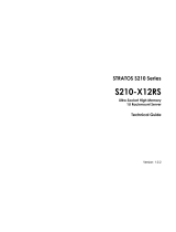
System
Component Overview
System Component Overview
Sys
5
4
3
2
1
1
2
3
4
System Components Overview
NO.COMPONENT
1 Internal SAS interface module (x4)
2 Fan module (x4)
3 HDD (x60)
4 Control panel

ABOUT THE M4600H COMPONENT PLACEMENT
1-5
Component Placement
Component Placement Schema
System Front View
System Front View
HDD
0
HDD
1
HDD
2
HDD
3
HDD
4
HDD
5
HDD
12
HDD
13
HDD
14
HDD
15
HDD
16
HDD
17
HDD
6
HDD
7
HDD
8
HDD
9
HDD
10
HDD
11
HDD
18
HDD
19
HDD
20
HDD
21
HDD
22
HDD
23
HDD
24
HDD
25
HDD
26
HDD
27
HDD
28
HDD
29
HDD
30
HDD
31
HDD
32
HDD
33
HDD
34
HDD
35
HDD
36
HDD
37
HDD
38
HDD
39
HDD
40
HDD
41
HDD
42
HDD
43
HDD
44
HDD
45
HDD
46
HDD
47
HDD
48
HDD
49
HDD
50
HDD
51
HDD
52
HDD
53
HDD
54
HDD
55
HDD
56
HDD
57
HDD
59
HDD
59
PSU
SIM
SIM
PSU
FAN
FAN
FAN
FAN
HDD
0
HDD
1
HDD
2
HDD
3
HDD
4
HDD
5
HDD
6
HDD
7
HDD
8
HDD
9
HDD
10
HDD
11
HDD
1
2
HDD
1
3
H
DD
1
4
HDD
1
5
HDD
1
6
HDD
17
H
DD
1
8
H
DD
19
HDD
2
0
HDD
21
H
DD
22
HDD
23
HDD
24
HDD
2
5
HD
D
2
6
HDD
27
HDD
2
8
HDD
29
HD
D
30
HD
D
31
HDD
32
HDD
33
HD
D
3
4
HDD
35
HDD
4
8
HDD
49
HD
D
50
HDD
5
1
HDD
5
2
HDD
53
HD
D
5
4
HD
D
55
HDD
56
HDD
5
7
HD
D
59
HDD
59
HDD
36
HDD
3
7
H
DD
3
8
HDD
3
9
HDD
40
HDD
41
H
DD
4
2
H
DD
43
HDD
44
HDD
45
H
DD
46
HDD
47
HDD Array 1 HDD Array 2 HDD Array 3 HDD Array 4 HDD Array 5
5
4
32
1
ISIM 0 ISIM 1 ISIM 2 ISIM 3
System Front View
NO.ITEM
1 Control panel
2 Front grill
5
4
3
2
1
2
1

ABOUT THE M4600H SYSTEM FRONT VIEW
1-6
Control Panel
Control Panel
Note:
See the HDD array definition in section “Component Place-
ment”.
Control Panel
NO.ICON ITEM
1 Power button with LED
5
4
3
2
1
1
2
3
4
5
6
7
8
9
10
11
12
2 System status LED
3 Fan status LED
4 PSU status LED
5 SIM status LED
6 ISIM status LED
7 ID button with LED
8 HDD array 1 LED
9 HDD array 2 LED
Control Panel (Continued)
NO.ICON ITEM
1
2

ABOUT THE M4600H SYSTEM REAR VIEW
1-7
System Rear View
System Rear View
10 HDD array 3 LED
11 HDD array 4 LED
12 HDD array 5 LED
Control Panel (Continued)
NO.ICON ITEM
3
4
5
System Rear View
NO.ITEM
1 Fan module (x4)
2 SIM module (x2)
3 Power supply unit (x2)
SERVICE
6Gb/s
S
A
S
CASCADE IN
CASCADE OUT
HOST 0 HOST 1 HOST 2 HOST 3
SERVICE
6Gb/s
S
A
S
CASCADE IN
CASCADE OUT
HOST 0 HOST 1 HOST 2 HOST 3
1
2
3

ABOUT THE M4600H SYSTEM REAR VIEW
1-8
SIM Module
SIM Module
SIM Module Features
NO.ICON ITEM
1 MiniSAS port (x4)
2 System power LED
3 SIM status LED
SERVICE
6Gb/s
S
A
S
CASCADE IN
CASCADE OUT
HOST 0 HOST 1 HOST 2 HOST 3
0123
1
2
3
4
5
6
7
4 SIM ID LED
5 MiniSAS port status LED (x4)
6Service port
7 MiniSAS port activity LED (x4)
SIM Module Features
NO.ICON ITEM
OK

ABOUT THE M4600H LED STATUS DEFINITIONS
1-9
LED Status Definitions
The LED status is defined as follows:
LED Status
MODULE NAME LED COLOR CONDITION DESCRIPTION
Front Panel (Enclosure)
System Power Green
On System power on
Off System power off
Identify LED Blue
On
Enclosure identifier, not
identified
Off Not identified
System Status Amber
On System fault
Off System good
Fan Status Amber
On Fan fault
Off Fan good
PSU Status Amber
On PSU fault
Off PSU good
SIM Status Amber
On SIM fault
Off SIM good
ISIM Status Amber
On ISIM fault
Off ISIM good
HDD Status (1 to 5) Amber
On HDD row# fault
Off HDD row# good

ABOUT THE M4600H LED STATUS DEFINITIONS
1-10
Hard Drive Tray
Active (driven by hard drive) Green
On HDD ready for access
Blink
During spin up or accessing
HDDs
Off HDD not ready
Identify Blue
Blink HDD identifier
On Ready for remove
Off Normal
Status Amber
On
Hard drive failed or port dis-
able
Off Normal
Hot Spare Purple On
Hot spare indicator is turned
on
Cons Check Blue->purple->blue->purple On
Consistency check In prog-
ress indicator is turned on
Rebuild/Remap Blue->amber->blue->amber Blink
Rebuild/remap indicator is
turned on
Power Supply /Cooling Mod-
ule
Power Supply Status Amber
On SPS failed
Off SPS healthy
Cooling Fans Status Amber
On Any fan failure
Off All fans healthy
LED Status (Continued)
MODULE NAME LED COLOR CONDITION DESCRIPTION

ABOUT THE M4600H LED STATUS DEFINITIONS
1-11
SIM
Power Green
On Power on
Off Power off
Status Amber
On SIM fault
Off
Power off, or disabled by
other SIM
Identify Blue
Blink SIM identifier
Off Normal
SAS Link/ Status Green/Amber
Green=On, Amber=Off SAS link up
Green=Off, Amber=Off SAS link down
Green=Blink, Amber=Off SAS link with activities
Green=Blink, Amber=On
SAS link with activities but
physical link down
ISIM
Power Green
On Power on
Off Power off
Status Amber
On ISIM fault
Off
Power off, or disabled by the
other ISIM
Identity Blue
Blink ISIM identifier
Off Normal
LED Status (Continued)
MODULE NAME LED COLOR CONDITION DESCRIPTION

ABOUT THE M4600H LED STATUS DEFINITIONS
1-12
HDD LEDs
HDD LEDs
ISIM LEDs
ISIM LEDs
HDD LEDs
NO.ICON ITEM
1
HDD status/ ID LED
2 HDD activity LED
HDD
ISIM LEDs
NO.ICON ITEM
1ISIM ID LED
2 ISIM status LED
3 Power LED
ISIM

Safety Information
Chapter 2
/