Page is loading ...

This guide provides the system overview and specifications for Hitachi Advanced Server
DS120, including hardware component descriptions, ports, network interface cards, and LEDs.
MK-97HAS010-00
April 2018
Hitachi Advanced Server
DS120 Hardware Guide

© 2018 Hitachi Vantara Corporation. All rights reserved.
No part of this publication may be reproduced or transmitted in any form or by any means, electronic or mechanical, including
photocopying and recording, or stored in a database or retrieval system for commercial purposes without the express written permission
of Hitachi, Ltd., or Hitachi Vantara Corporation (collectively, “Hitachi”). Licensee may make copies of the Materials provided that any
such copy is: (i) created as an essential step in utilization of the Software as licensed and is used in no other manner; or (ii) used for
archival purposes. Licensee may not make any other copies of the Materials. "Materials" mean text, data, photographs, graphics, audio,
video and documents.
Hitachi reserves the right to make changes to this Material at any time without notice and assumes no responsibility for its use. The
Materials contain the most current information available at the time of publication.
Some of the features described in the Materials might not be currently available. Refer to the most recent product announcement
for information about feature and product availability, or contact Hitachi Vantara Corporation at https://support.HitachiVantara.com/
en_us/contact-us.html.
Notice: Hitachi products and services can be ordered only under the terms and conditions of the applicable Hitachi agreements. The
use of Hitachi products is governed by the terms of your agreements with Hitachi Vantara Corporation.
By using this software, you agree that you are responsible for:
1) Acquiring the relevant consents as may be required under local privacy laws or otherwise from authorized employees and other
individuals to access relevant data; and
2) Verifying that data continues to be held, retrieved, deleted, or otherwise processed in accordance with relevant laws.
Notice on Export Controls. The technical data and technology inherent in this Document may be subject to U.S. export control laws,
including the U.S. Export Administration Act and its associated regulations, and may be subject to export or import regulations in
other countries. Reader agrees to comply strictly with all such regulations and acknowledges that Reader has the responsibility to
obtain licenses to export, re-export, or import the Document and any Compliant Products.
EXPORT CONTROLS - Licensee will comply fully with all applicable export laws and regulations of the United States and other
countries, and Licensee shall not export, or allow the export or re-export of, the Software, API, or Materials in violation of any such laws
or regulations. By downloading or using the Software, API, or Materials, Licensee agrees to the foregoing and represents and
warrants that Licensee is not located in, under the control of, or a national or resident of any embargoed or restricted country.
Hitachi is a registered trademark of Hitachi, Ltd., in the United States and other countries.
AIX, AS/400e, DB2, Domino, DS6000, DS8000, Enterprise Storage Server, eServer, FICON, FlashCopy, IBM, Lotus, MVS, OS/390,
PowerPC, RS6000, S/390, System z9, System z10, Tivoli, z/OS, z9, z10, z13, z/VM, and z/VSE are registered trademarks or
trademarks of International Business Machines Corporation.
Active Directory, ActiveX, Bing, Excel, Hyper-V, Internet Explorer, the Internet Explorer logo, Microsoft, the Microsoft Corporate Logo,
MS-DOS, Outlook, PowerPoint, SharePoint, Silverlight, SmartScreen, SQL Server, Visual Basic, Visual C++, Visual Studio,
Windows, the Windows logo, Windows Azure, Windows PowerShell, Windows Server, the Windows start button, and Windows Vista
are registered trademarks or trademarks of Microsoft Corporation. Microsoft product screen shots are reprinted with permission from
Microsoft Corporation.
All other trademarks, service marks, and company names in this document or web site are properties of their respective owners.

TABLE OF CONTENTS
I
TABLE OF CONTENTS
About the System
Introduction . . . . . . . . . . . . . . . . . . . . . . . . . . . . . . . . . . . . . . . . . . . . . . . . . . . . . . . . . . 1
System Features. . . . . . . . . . . . . . . . . . . . . . . . . . . . . . . . . . . . . . . . . . . . . . . . . . 1
SKU information . . . . . . . . . . . . . . . . . . . . . . . . . . . . . . . . . . . . . . . . . . . . . . . 3
Package Contents . . . . . . . . . . . . . . . . . . . . . . . . . . . . . . . . . . . . . . . . . . . . . . . . . . . . . 4
A Tour of the System . . . . . . . . . . . . . . . . . . . . . . . . . . . . . . . . . . . . . . . . . . . . . . . . . . 5
System Overview . . . . . . . . . . . . . . . . . . . . . . . . . . . . . . . . . . . . . . . . . . . . . . . . . 5
System Front View. . . . . . . . . . . . . . . . . . . . . . . . . . . . . . . . . . . . . . . . . . . . . . . . 6
Front Control Panel (FCP). . . . . . . . . . . . . . . . . . . . . . . . . . . . . . . . . . . . . . . 7
System Rear View . . . . . . . . . . . . . . . . . . . . . . . . . . . . . . . . . . . . . . . . . . . . . . . . 7
System R
ear I/O .
. . . . . . . . . .
. . . . . . . . . . . . . . . . . . . .
. . . . . . . . . . . . . . . . .
8
Power Sub-System . . . . . . . . . . . . . . . . . . . . . . . . . . . . . . . . . . . . . . . . . . . . . 9
HDD / M.2 Adapter Configu
ration .
. . . . . . . . . . . . . . . . . .
.
.
.
.
. . . . . . . . . 10
Full 2.5” HDD Configuration . . . . . . . . . . . . . . . . . . . . . . . . . . . . . . . . . . . 10
NVMe SSD M.2 Adapter Add-On Card (Optional) . . . . . . . . . . . . . . . 11
LED Status Descriptions . . . . . . . . . . . . . . . . . . . . . . . . . . . . . . . . . . . . . . . . . 12
Front Control Panel LEDs . . . . . . . . . . . . . . . . . . . . . . . . . . . . . . . . . . . . . . 12
BMC Management Port LEDs . . . . . . . . . . . . . . . . . . . . . . . . . . . . . . . . . . 12
Storage Drive LED. . . . . . . . . . . . . . . . . . . . . . . . . . . . . . . . . . . . . . . . . . . . . 13

CONVENTIONS
IX
Conventions
Several different typographic conventions are used throughout this manual. Refer to the
following examples for common usage.
Bold type face denotes menu items, buttons and application names.
Italic type face denotes references to other sections, and the names of the folders, menus,
programs, and files.
<Enter> type face denotes keyboard keys.
WARNING!
Warning information appears before the text it references and should not be ignored as the
content may prevent damage to the device.
CAUTION!
CAUTIONS APPEAR BEFORE THE TEXT IT REFERENCES, SIMILAR TO NOTES AND WARNINGS. CAUTIONS, HOWEVER,
APPEAR IN CAPITAL LETTERS AND CONTAIN VITAL HEALTH AND SAFETY INFORMATION.
Note:
Highlights general or useful information and tips.
!
!

PRECAUTIONARY MEASURES
X
Precautionary Measures
Read all caution and safety statements in this document before performing any of the
instructions. To reduce the risk of bodily injury, electrical shock, fire, and equipment dam-
age, read and observe all warnings and precautions in this chapter before installing or
maintaining your system. To avoid personal injury or property damage, before you begin
installing the product, read, observe, and adhere to all of the following instructions and
information. The following symbols may be used throughout this guide and may be
marked on the product and / or the product packaging.
Safety Instructions about your system
In the event of a conflict between the information in this guide and information provided
with the product or on the website for a particular product, the product documentation
takes precedence.
Your system should be integrated and serviced only by technically qualified persons.
You must adhere to the guidelines in this guide and the assembly instructions in related
chapters to ensure and maintain compliance with existing product certifications and
approvals. Use only the described, regulated components specified in this guide. Use of
other products / components will void the UL Listing and other regulatory approvals of
the product, and may result in noncompliance with product regulations in the region(s) in
which the product is sold.
Table 1: Warning and Cautions
CAUTION
Indicates the presence of a hazard that may cause minor personal injury or prop-
erty damage if the CAUTION is ignored.
WARNING
Indicates the presence of a hazard that may result in serious personal injury if the
WARNING is ignored.
Indicates potential hazard if indicated information is ignored.
Indicates shock hazards that result in serious injury or death if safety instructions
are not followed.
Indicates hot components or surfaces.
Indicates do not touch fan blades, may result in injury.
Remove the system from the rack to disconnect power system.

PRECAUTIONARY MEASURES
XI
Intended Application Uses
This product was evaluated as Information Technology Equipment (ITE), which may be
installed in offices, schools, computer rooms, and similar commercial type locations. The
suitability of this product for other product categories and environments (such as medical,
industrial, residential, alarm systems, and test equipment), other than an ITE application,
may require further evaluation.
Site Selection
The system is designed to operate in a typical office environment. Choose a site that is:
Clean, dry, and free of airborne particles (other than normal room dust).
Well-ventilated and away from sources of heat including direct sunlight and radia-
tors.
Away from sources of vibration or physical shock.
Isolated from strong electromagnetic fields produced by electrical devices.
In regions that are susceptible to electrical storms, we recommend you plug your
system into a surge suppressor and disconnect telecommunication lines to your
modem during an electrical storm.
Provided with a properly grounded wall outlet.
Provided with sufficient space to access the power system, because they serve as the
product's main power disconnect.
Provided with either two independent DC power system or two independent phases
from a single power system.
Equipment Handling Practices
Reduce the risk of personal injury or equipment damage:
Conform to local occupational health and safety requirements when moving and
lifting equipment.
Use mechanical assistance or other suitable assistance when moving and lifting
equipment.
The enclosure is designed to carry only the weight of the system sled. Do not use
this equipment as a workspace. Do not place additional load onto any equipment
in this system.
Indicates two people are required to safely handle the system.
Table 1: Warning and Cautions (Continued)

PRECAUTIONARY MEASURES
XII
To reduce the weight for easier handling, remove any easily detachable compo-
nents.
Never lift or move your system soley by the handle on the component.
Power and Electrical Warnings
System Access Warnings
Rack Mount Warnings
The following installation guidelines are required by UL for maintaining safety compliance
when installing your system into a rack.
The equipment rack must be anchored to an unmovable support to prevent it from tip-
ping when your system or piece of equipment is extended from it. The equipment rack
must be installed according to the rack manufacturer's instructions.
CAUTION!
MAKE SURE THE SYSTEM IS REMOVED FROM THE RACK BEFORE SERVICING ANY NON-HOT PLUG COMPONENTS.
T
HE BUS BAR CLIPS MUST BE DISCONNECTED FROM THE POWER SYSTEM IN ORDER TO FULLY SEPARATE THE SYS-
TEM FROM THE POWER SOURCE.
CAUTION!
TO AVOID RISK OF ELECTRIC SHOCK, DISCONNECT ALL CABLING FROM THE SYSTEM AND REMOVE THE SYSTEM
FROM THE RACK.
CAUTION!
TO AVOID PERSONAL INJURY OR PROPERTY DAMAGE, THE FOLLOWING SAFETY INSTRUCTIONS APPLY WHENEVER
ACCESSING THE INSIDE OF THE PRODUCT:
Disconnect from the power source by removing the system from the rack.
Disconnect all cabling running into the system.
Retain all screws or other fasteners when servicing. Upon completion servicing, secure
with original screws or fasteners.
CAUTION!
IF THE SERVER HAS BEEN RUNNING, ANY INSTALLED HDD MODULES MAY BE HOT.
CAUTION!
UNLESS YOU ARE ADDING OR REMOVING A HOT-PLUG COMPONENT, ALLOW THE SYSTEM TO COOL BEFORE SER-
VICING.
CAUTION!
TO AVOID INJURY DO NOT CONTACT MOVING FAN BLADES. IF YOUR SYSTEM IS SUPPLIED WITH A GUARD OVER THE
FAN, DO NOT OPERATE THE SYSTEM WITHOUT THE FAN GUARD IN PLACE.
!
!
!
!
!
!

PRECAUTIONARY MEASURES
XIII
Install equipment in the rack from the bottom up, with the heaviest equipment at the bot-
tom of the rack.
Extend only one piece of equipment from the rack at a time.
You are responsible for installing a main power disconnect for the entire rack unit. This
main disconnect must be readily accessible, and it must be labeled as controlling power to
the entire unit, not just to the system(s).
To avoid risk of potential electric shock, a proper safety ground must be implemented for
the rack and each piece of equipment installed in it.
Elevated Operating Ambient - If installed in a closed or multi-unit rack assembly, the oper-
ating ambient temperature of the rack environment may be greater than room ambient.
Therefore, consideration should be given to installing the equipment in an environment
compatible with the maximum ambient temperature (Tma) specified by the manufac-
turer.
Reduced Air Flow - Installation of the equipment in a rack should be such that the amount
of air flow required for safe operation of the equipment is not compromised.
Mechanical Loading - Mounting of the equipment in the rack should be such that a haz-
ardous condition is not achieved due to uneven mechanical loading.
Circuit Overloading - Consideration should be given to the connection of the equipment
to the supply circuit and the effect that overloading of the circuits might have on over-cur-
rent protection and supply wiring. Appropriate consideration of equipment nameplate
ratings should be used when addressing this concern.
Reliable Earthing - Reliable earthing of rack-mounted equipment should be maintained.
Particular attention should be given to supply connections other than direct connections
to the branch circuit (e.g. use of power strips).
Electrostatic Discharge (ESD)
Always handle boards carefully. They can be extremely sensitive to ESD. Hold boards only
by their edges without any component and pin touching. After removing a board from its
protective wrapper or from the system, place the board component side up on a
grounded, static free surface. Use a conductive foam pad if available but not the board
wrapper. Do not slide board over any surface.
CAUTION!
ESD CAN DAMAGE DRIVES, BOARDS, AND OTHER PARTS. WE RECOMMEND THAT YOU PERFORM ALL PROCEDURES
AT AN ESD WORKSTATION. IF ONE IS NOT AVAILABLE, PROVIDE SOME ESD PROTECTION BY WEARING AN ANTI-
STATIC WRIST STRAP ATTACHED TO CHASSIS GROUND -- ANY UNPAINTED METAL SURFACE -- ON YOUR SERVER
WHEN HANDLING PARTS.
!

PRECAUTIONARY MEASURES
XIV
Cooling and Airflow
Please be aware that slots and openings on the front and rear side of the chassis are
designed for ventilation; to make sure reliable operation of your system and to protect it
from overheating, these openings must not be covered or blocked. The openings should
never be covered or blocked by placing the product on a bed, sofa, rug, or other similar
surface. This product should never be placed near or over a radiator or heat register, or in a
built-in installation unless proper ventilation is provided.
Laser Peripherals or Devices
Use certified and rated Laser Class I for Optical Transceiver product.
Heed safety instructions: Before working with the system, whether using this manual or
any other resource as a reference, pay close attention to the safety instructions. Adhere to
the assembly instructions in this manual to ensure and maintain compliance with existing
product certifications and approvals. Use only the described, regulated components spec-
ified in this manual. Use of other products / components will void the UL listing and other
regulatory approvals of the product and will most likely result in non-compliance with
product regulations in the region(s) in which the product is sold.
System power on/off: To remove power from system, you must remove the system from
rack. Make sure the system is removed from the rack before opening the chassis, adding,
or removing any non hot-plug components.
Hazardous conditions, devices and cables: Hazardous electrical conditions may be
present on power, telephone, and communication cables. Turn off the system and discon-
nect the cables attached to the system before opening it. Otherwise, personal injury or
equipment damage can result.
CAUTION!
CAREFULLY ROUTE CABLES AS DIRECTED TO MINIMIZE AIRFLOW BLOCKAGE AND COOLING PROBLEMS. FOR
PROPER COOLING AND AIRFLOW, OPERATE THE SYSTEM ONLY WITH THE CHASSIS COVERS* / AIR DUCT INSTALLED.
O
PERATING THE SYSTEM WITHOUT THE COVERS / AIR DUCT IN PLACE CAN DAMAGE SYSTEM PARTS. TO INSTALL
THE COVERS* / AIR DUCT:
Check first to make sure you have not left loose tools or parts inside the system.
Check that cables, add-in cards, and other components are properly installed.
Attach the covers* / air duct to the chassis according to the product instructions.
* May not apply to all systems.
CAUTION!
TO AVOID RISK OF RADIATION EXPOSURE AND / OR PERSONAL INJURY:
Do not open the enclosure of any laser peripheral or device.
Laser peripherals or devices are not serviceable.
Return to manufacturer for servicing.
!
!

PRECAUTIONARY MEASURES
XV
Electrostatic discharge (ESD) and ESD protection: ESD can damage drives, boards, and
other parts. We recommend that you perform all procedures in this chapter only at an ESD
workstation. If one is not available, provide some ESD protection by wearing an antistatic
wrist strap attached to chassis ground any unpainted metal surface on the server when
handling parts.
ESD and handling boards: Always handle boards carefully. They can be extremely sensi-
tive to electrostatic discharge (ESD). Hold boards only by their edges. After removing a
board from its protective wrapper or from the server, place the board component side up
on a grounded, static free surface. Use a conductive foam pad if available but not the
board wrapper. Do not slide board over any surface.
Installing or removing jumpers: A jumper is a small plastic encased conductor that slips
over two jumper pins. Some jumpers have a small tab on top that can be gripped with fin-
gertips or with a pair of fine needle nosed pliers. If the jumpers do not have such a tab,
take care when using needle nosed pliers to remove or install a jumper; grip the narrow
sides of the jumper with the pliers, never the wide sides. Gripping the wide sides can dam-
age the contacts inside the jumper, causing intermittent problems with the function con-
trolled by that jumper. Take care to grip with, but not squeeze, the pliers or other tool used
to remove a jumper, or the pins on the board may bend or break.
General Information
Before servicing this system, it is recommened to read this guide completely to be aware
of any safety issues or requirements involved in the servicing of this system.
Assembly Safety Guidelines
The power system in this product contains no user-serviceable parts.
Refer servicing only to qualified personnel.
The system is designed to operate in a typical office environment.
Choose a site that is:
Clean and free of airborne particles (other than normal room dust).
Well ventilated and away from sources of heat including direct sunlight.
Away from sources of vibration or physical shock.
Isolated from strong electromagnetic fields produced by electrical devices.
In regions that are susceptible to electrical storms, we recommend you plug
your system into a surge suppressor and disconnect telecommunication lines
to your modem during an electrical storm.
Provided with a properly grounded wall outlet.
Provided with sufficient space to access the power system, because they serve
as the product's main power disconnect.

PRECAUTIONARY MEASURES
XVI
WARNING!
The system is safety certified as rack-mounted equipment for use in a server room
or computer room, using an approved customer rack.
The enclosure is designed to carry only the weight of the system sled. Do not place
additional load onto any equipment.
Heavy object. Indicates two people are required to safely handle the system.

About the System
This guide provides the system overview and specifications for Hitachi Advanced
S
erver DS120, including hardware component descriptions, ports, network interface
cards, and LEDs.

ABOUT THE SYSTEM INTRODUCTION
1
1.1 Introduction
This document provides an overview of the hardware features of the chassis,
troubleshooting information, and instructions on how to add and replace components of
the server.
System Features
The system comprises a 1U/30.7” long chassis. Major features include:
Chipset: Intel
®
C624
Processors (x2): Intel® Xeon® Processor Scalable Family (codename Skylake-SP)
Expansion: See SKU information on page 3 for more information.
Memory: Up to 24 DIMM slots are available; ECC DDR4 2666 MT/s RDIMM memory
Network*:
Dedicated
GbE management NIC port from PHY RTL8211 to BMC
Intel® C624 as 2x or 4x 10GbE integrated network solution with PHY (optional)*
*The dual port or quad port PHY card is installed to OCP mezzanine slot
Specifications
Note:
The system supports: 500W and 800W Titanium/Platinum redundant PSU, 100-240VAC 50/
60Hz, AC/ HVDC; 1100W redundant DC PSU: Acbe I/P: DC -39 - - 72v, 37A max.
Table 1.1: System Specifications
SPECIFICATIONS DESCRIPTION
Form factor 1U rack mount
Chassis dimensions
(W x H x D)
440mm x 43.2 mm x 780 mm
17.3" x 1.7" x 30.7"
Processor
Processor type:
Intel® Xeon® Processor Scalable Family (codename Skylake-SP)
Max. TDP support:
165W, Optimized power delivery for 85W, VRD 13
Number of processors: 2
Internal Interconnect: 10.4 GT/s, 9.6 GT/s
Chipset
Intel
® C624
Memory
Total slots: 24
Memory type: DDR4 2666 MT/s RDIMM
Memory size: 8GB, 16GB, 32 GB*
*More options refer to the AVL

ABOUT THE SYSTEM SYSTEM FEATURES
2
Storage controller
Onboard (Intel® C624):
(8) SATA 6Gbps port with (2) mini-SAS HD connector
(6) sSATA 6Gbps port with (1) mini-SAS HD connector (reserved) and
(2) 7-pin SATA port (reserved for SATA DOM)
Networking
Dedicated GbE management NIC port from PHY RTL8211 to BMC
Intel® C621 as 2x or 4x GbE integrated network solution with PHY (optional)
Intel® C624 as 2x or 4x10GbE integrated network solution with PHY (optional)
Expansion slots
See SKU information on page 3 for more information.
Storage
2.5” SKU:
Tiered SKU:
(8) SATA/SAS SSD/HDD (SFF-8680)
(4) SATA/SAS SSD/HDD or NVMe SSD (SFF-8639)
All Flash SKU:
(12) SATA SSD or
(12) NVMe SSD
Onboard storage (2) SATADOM (optional)
Video Integrated Aspeed AST2500 with 8MB video memory
Network options
(1) GbE dual or quad port OCP mezzanine PHY card (Optional)*
(1) 10GbE dual or quad port OCP mezzanine PHY card (Optional)*
Front I/O
Power/ID/Reset Buttons
Power/ID/Status LEDs
(2) USB 3.0 ports
Rear I/O
(2) USB 3.0 ports
(1) VGA port
(1) RS232 serial port
(1) GbE RJ45 management port
(1) ID LED
(1) MicroSD slot
TPM Yes (optional, SPI mode)
ACPI ACPI compliance, S0, S5 support
Power supply
500W and 800W Titanium/Platinum redundant PSU, 100-240VAC 50/60Hz,
AC/HVDC support
1100W redundant DC PSU: Acbel I/P: DC -39 - -72V, 37A max.
Table 1.1: System Specifications (Continued)
SPECIFICATIONS DESCRIPTION
6x SSD from CPU0
6x SSD from CPU1
SATA/NVMe SATA/NVMe SATA/NVMe SATA/NVMe SATA/NVMe SATA/NVMe
SATA/NVMe SATA/NVMe SATA/NVMe SATA/NVMe SATA/NVMe SATA/NVMe

ABOUT THE SYSTEM SYSTEM FEATURES
3
Note:
Internal USB port is reserved for UDK USB drive installation only. Feature hot plug is not available on this
internal USB port.
SKU information
2.5” Tiered SKU
System rating
100-120/200-240Vac, 50/60Hz, 6.5/3.3A or 240Vdc, 3A (Per PSU inlet) for
PSU:500W and 800W
100-120/200-240Vac, 50/60Hz, 7.4/4A or 240Vdc, 3.7A (Per PSU inlet) for
PSU:800W
-39V- -72Vdc, 28A max. (Per PSU inet)
Fan (8) dual rotor fans (15+1 redundant)
System management IPMI v2.0 Compliant, on board "KVM over IP" support
Operating environment
Operating temperature: 5°C to 40°C (41°F to 104°F)
Non-operating temperature: -40°C to 70°C (-40°F to 158°F)
Operating relative humidity: 20% to 85%RH
Non-operating relative humidity: 10% to 95%RH
Table 1.1: System Specifications (Continued)
SPECIFICATIONS DESCRIPTION
CPU0
CPU1
Slot 3 (CPU 1)
LP-MD2
PCIex16
Slot 1A (CPU 0)
Slot 4 (CPU 0)
FHHL
PCIex16
12x SATA
SAS mezz
PCIex16
PCH
12x SAS
OCP
mezz
PCIex16
PCIe x 8
Slot 2 (CPU 1)
PCIe x 8
1 x16 LP-MD2 + 1 x8 FHHL PCIe Card + 4 NVMe SSD
S
A
S
me
z
z
PCI
e
x
16
SAS/ SATA SAS/ SATA SAS/ SATA SAS/ SATA U.2 U.2
SAS/ SATA SAS/ SATA SAS/ SATA SAS/ SATA U.2 U.2
Legend:
U.2 = SAS/SATA/NVMe

ABOUT YOUR SYSTEM PACKAGE CONTENTS
4
1.2 Package Contents
(1) DS120-1U system
(2) processor heat sinks
(1) power supply unit
(1) power cord
(optional)
Note:
For exact shipping contents, contact your sales representative.

ABOUT THE SYSTEM A TOUR OF THE SYSTEM
5
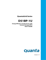
1.3 A Tour of the System
System Overview
The server is available as a 2.5” storage drive configuration.
The 2.5” storage drive system overview is displayed in the following image:
Figure 1.
2.5” Storage Drive System Component Overview
Table 2: Component Overview
NO.ITEM DESCRIPTIONS
1 Front control panel
2 Asset tag Record serial number or other important information
3 2.5” storage drive tray Housing up to twelve 2.5” storage drive (15mm)
4 USB port Connect to USB device
5 Thumb screw Secure the system to rack frame
6 Mainboard System mainboard
7 PSU assembly Redundant power supply unit assembly
8 Riser assembly (CPU1) Support PCIe add-on card installation with riser feature.
9 OCP slot (CPU0) Support OCP 2.0 mezzanine card installation.
13
8
6
14
7
10
11
9
1
2
3
4
5
12
Record serial number or other important information

ABOUT THE SYSTEM SYSTEM FRONT VIEW
6
System Front View
Figure 2. 2.5” Storage Drive System Front View
10 Riser assembly (CPU0) Support PCIe add-on card installation with riser feature.
11 PSU assembly Redundant power supply unit assembly
12 SuperCap carrier Housing SuperCap using in SAS mezzanine card or SAS add-on card
13 DIMM slots
(12) DDR4 DIMM slots per CPU
14 Fan module (8) System fan modules
Table 3: Front View
NO.NAME DESCRIPTIONS
1 Thumb screw Secure the system to rack frame
2 2.5” storage drive tray Housing up to twelve 2.5” storage drive (15mm):
3USB port Connect to USB device
4 Asset tag Record serial number or other important information
5 Front control panel
See Front Control Panel LEDs on page 12 for further information.
Table 2: Component Overview (Continued)
NO.ITEM DESCRIPTIONS
2
5
3 3
1 1
4

ABOUT THE SYSTEM SYSTEM REAR VIEW
7
Front Control Panel (FCP)
System Rear View
Figure 3. Front Control Panel
Table 4: Fr
ont Control Panel Descriptions
NO.ICON NAME DESCRIPTIONS
1
Power button with
LED
Power on / off
Blue on - S0 system power on; Off - S5 system power off
2 Reset button Soft reset system function
3
Identification button
with LED
Toggles ID LED, activate ID LED to identify system
Blue blinking - Identifier on front and rear chassis; Off - Normal.
4System Status LED
Provides critical and non-critical failure notification
Amber blinking - failed; Off - SEL cleared / good
Table 5: System Rear View
NO.FEATURE DESCRIPTIONS
1 Power sub-system
Main power supply unit (PSU0). See Power Sub-System on page 9.
2 System I/O ports
See System Rear I/O on page 8
3 Expansion slot Support OCP 2.0 mezzanine card installation (CPU0)
Reset
1 2 3 4
Reset
1
7
4
56
2 3
Figure 4. System Rear View
8 9

ABOUT THE SYSTEM SYSTEM REAR VIEW
8
System Rear I/O
4 Power sub-system
Main power supply unit (PSU1). See Power Sub-System on page 9.
5 Expansion slot PCIe expansion slot with LP MD-2 (CPU0)
6 Expansion slot PCIe expansion slot with LP MD-2 (CPU1)
7 Expansion slot PCIe expansion slot with LP MD-2 (CPU1)
8 Expansion slot PCIe expansion slot with LP MD-2 (CPU1)
9 Expansion slot PCIe expansion slot with FHHL (CPU0)
Figure 5. System Rear I/O
Table 6: System Rear I/O Descriptions
NO.ICON NAME DESCRIPTIONS
1 Dedicated NIC Dedicated RJ45 connector
2VGA connector
Maximum display resolution: 1920x1200 32bpp@60Hz
(reduced blanking)
3 COM A port DB9 port (Serial_A) for debug or terminal concentrator
4
USB 3.0 port
USB 1 port; connect to USB device
5 USB 0 port; connect to USB device
6 Identification LED Blue blinking - Identifier; Off - Normal.
7 MicroSD slot Backup BMC SEL.
Table 5: System Rear View (Continued)
NO.FEATURE DESCRIPTIONS
2
3
451 6 7
/