Page is loading ...

The elecTric eliTe - Assembly Instructions
Assembly Parts list
A. (4) Black Screw Covers
B. (2) 1/4-20 x 3.50 Hex Head Bolts
C. (1) 5/32 Allen Wrench
D. (2) Fender Washers
E. (2) Acorn Nuts
F. (3) 1/4-20 x 7/8 BHCS (THESE 3
ARE ALREADY THREADED IN THE
LIFT ASSEMBLY)
G. (2) Thick Black Washers
H. (1) 7/16 Wrench
I. (2) Locking Star Washers
J. 1 x 2 plastic cap
K. (2) 1/4-20 x 3/8 BHCS
A
B
CD
E
F
G
H
I
J
K
(2) (2)
Steps 1-4 attaching the steel base plate to the lifting assembly
Step 1: Lay the lifting assembly on a solid surface with the back side up as shown. Notice the circled Button Head
Bolt in the assembly union plate. DO NOT LOOSEN THE SINGLE BUTTON HEAD BOLT THAT IS NOTATED.
LOOSEN AND REMOVE THE 3 OTHER BOLTS TO ADD THE LIFTING ASSEMBLY TO THE BASE PLATE.
Step 2: Notice the (2) oversized holes in the Base Plate. The Single Button Head Bolt will go into the oversized hole
on the top right, while the other 3 holes should line up with the base. The center oversized hole is not used with
this unit.
Step 3: With the Base Plate over hanging the table about 2 inches, hold the Lifting Assembly above the Base Plate
and align the Single Button Bolt into the oversized hole. Place (1) 1/4-20 x 7/8 BHCS{F} through the base plate to
screw in the lifting assembly. *DO NOT OVER TIGHTEN AT THIS POINT, WAIT UNTIL ALL BUTTON HEADS HAVE
BEEN ADDED.
Step 4: Insert and thread the other (2) 1/4-20 x 7/8 BHCS{F} through the Base Plate and into the Lifting Assembly.
Once all (3) bolts are threaded in, tighten securely with the 5/32 allen wrench{C}. Lifting Assembly should be at
against the Base and all three bolts should look like the picture above.
Step 1, 2 Step 3 Step 4
lifting
assembly
top of steel base plate
not used
image shows back side of
lifting assembly lining up the button
head bolts
single
button
head
oversized
hole to
match with
button
head
screw
bottom of lifting assembly
three button heads that need
screwed in and tightened
oversized hole
matched
up with already
installed
button head
bottom of base plate

The elecTric eliTe - Assembly Instructions Raise the lifting assembly to attach the
shelf button and work surface
Step 8: Put (1) Locking Star Washer{I} on each of the 1/4 –20 x 3.50
Hex Head Bolts{B}.
Step 9: Insert the (2) 1/4-20 x 3.50 Hex Head Bolts{B} through the
holes in the Vertical Rail.
Step 10: Put (1) Fender Washer{D} on each of the 1/4-20 x 3.50
Hex Head Bolts{B} on the other side of the Vertical Rail.
Step 11: Lift the Work Surface up and align the holes in the Hor-
izontal Rail with the (2) 1/4-20 x 3.50 Hex Head Bolts{B}. Push the
Work Surface onto the Hex Head Bolts until the threads of the
bolts come through the Horizontal Rail.
Step 12: Put (1) Black Washer{G} and (1) Acorn
Nut{E} on the end of each of the Hex Head
Bolts. Using the 7/16 wrench{H} tighten the
Acorn Nuts securely.
Acorn Nuts
Step 5: Connecting the
power for the lifting
assembly. Go to the back
side of the lifting assem-
bly and turn the power
box to the left. Push the
plug securely into the
power box. Tilt back to a
vertical position.
Step 6: Connecting the controller from the shelf and cable to
the actuator/motor. Connect the cable from the controler into
port “A1“ on the power box. Then connect the loose cable from
the motor to the provided extension cable. Plug the other end
into the control box on the back into port 1 on the far right.
Step 7: Installing the electric switch
(DPG1C) and phone tray. After the base has been
attched, prep the tray by unscrewing the e-nuts
until they are on the end of the bolt. Slide the tray
on using the vertical channels of the lifting assem-
bly as shown. Slide the tray up about 2 inches (this
can be changed at any time), and lightly tighten
the two bolts with the provided allen wrench.
Once you have con-
nected your cables,
plug the unit into an
outlet and press up
against the bottom
of the button, you
will feel a ‘click’.
Raise the unit 3/4 of
the way up like the
picture to the left.
STEP 11
Fender
Washers
horizontal
rail
Work
Surface
We suggest keeping
the lifting assembly
raised up, to step 12.
Once step 12 is
completed the unit
can be lowered to
the complete sitting
position.
Provided
Extension Cable
STEP 8,9,10
Fender
Washer
1/4-20 x 3.50
Hex Head Bolt
Locking Star
Washer
Locking Star
Washer
STEP 12
Black Washers
Acorn Nuts
Shelf and controller
button
STEP 5
STEP 6
STEP 7
STEP 5

STEP 13 Adding the Horizontal Monitor Arm
The elecTric eliTe - Assembly Instructions
Step 13: Identify the e-nuts(pictured above) that will hold the monitor bar. Loosen each
e-nut to about one thread to slide onto the rails.
Step 14: Slide on the monitor rail by using the bottom rail pictured above. Line up the
monitor rail to the desired location(usually centered).
Step 15: Identify the two hex head bolts holding the monitor rail pictured above
(located on the back of the unit). Once you have the monitor bar to your desired
location, tighten each bolt with the provided 7/16 wrench to a snug position.
Step 16: Adding the end-cap to your horizontal bar. On the exposed side of the rail
you will need to place the provided 1x2” rectangular black plastic cap{J}. Secure the
cap by adding (2) 3/8” button head bolts{K} with the provided allen wrench.
Step 17: Place black caps over any exposed hex head bolts. Follow the instructions
below to mount your monitor.
STEP 13 STEP 14 STEP 15 STEP 16
e-nuts to
loosen
hex head bolts
need tightened
J. 1x2”
end cap
K. button
head bolts
back side
Raise the lifting assembly to attach the
shelf button and work surface
Fender
Washer

The STabilizaTion leg
Your adjustable height desk top unit comes with an adjustable leg that can be used to give you maxi-
mum stability when you are using “The Kangaroo” in the standing position.
Raise the Kangaroo work surface to your desired standing height and tighten the work surface brake.
Place the adjustable leg under the work surface and loosen the adjustable leg brake. Only loosen the
brake by a turn or two, too much and the brake will disengage from the slot.
Extend the adjustable leg until it engages the bottom of the work surface and then tighten the adjust-
able leg brake.
The leg is shipped with the extension section installed to give you additional height adjustment. If this
is too tall for your application, simply unscrew the extension selection.
If you have the taller version of the leg there is no top extension selection.
A. Extension selection
B. Extension selection screws into this location
AlwAys remove the stAbilizAtion leg before
lowering the unit
The elecTric eliTe - IN USE INSTRUCTIONS The Electric Elite is designed to hold (2)
monitors on the VESA 75 x 75 or 100 x
100mm compatible brackets and your
keyboard and mouse on the main work
surface. The Electric Elite has a spring that
assists in raising/lowering your monitors and
works best when your monitors are in place.
This reduces the amount of pressure needed
to lower the monitors.
The main work surface is powered by an
electric motor and can lift up to 150lbs.
When raising and lowering the unit, please
be aware of your surroundings and cable
lengths. When lowering be sure to remove
the leg and make sure no objects are
obstructing the down travel.
To move the mount
horizontally closer
or farther apart, simply
loosen the bolt
attached to the hori-
zontal monitor rail (B)
by a single turn with
a 5/32 allen wrench.
Once you have
reached the desired
position re-tighten
the bolt.
Raise and lower the monitor rail by
loosening the monitor brake(A) and either
lift up or push down on the monitor rail(B).
Once the monitors reach your desired level,
tighten the monitor brake.
Raise and lower the main work surface by
pressing up and down respectably on the
button surface.
B. horizontal
monitor rail
A. monitor
brake
C. control
button
The conTrol buTTon
The controller button now has expanded features including bluetooth, memory settings, digital display, sit/stand
reminders, and auto-drive. To learn the programming functions, faqs, and troubleshooting of the control button
please visit the orange link below or scan the qr code to the right. For basic operation simply press down on the
controller to lower and lift the controller to raise. Your unit is pre-programmed
to only auto-drive when favorite heights are set. If there are no favorites the unit
will only move continuously while holding the button down. !!!!ALERT when using
autodrive you accept full responsibility when operating the desk and understand
the danger that can occur. Make sure no items are between the work surface and
base plate when lowering or above the unit when raising!!!
hTTpS://www.ergodeSkTop.com/SiTeS/defaulT/fileS/ergo-conTrol-manual.pdf

THE
KANGAROO ELITE
HORIZONTAL BAR ADJUSTMENT INSTRUCTIONS
If
you have
an
offset
weight
on
your
Elite and want
to
move
your
main/larger
monitor
more in line
with
your
eyes, by moving the entire
horizontal
bar
left
or
right
please
follow
the steps below.
Step 1: Start
off
by removing
your
monitors
from
the unit.
Raise
the
unit
to
the standing
position,
tighten
the brakes and slide the
unit
around
to
face the back side
of
the
lifting
assembly.
Shown below.
BACK
SIDE
OF
UNIT
MONITOR
BRAKE
Step 2: Remove the
two
black plastic caps notated above
with
a set
of
pliers
or
a
flat
head screw driver.
Step 3: Loosen the
two
exposed bolts by
only
1 /2
to
a
full
turn
with
a 7/ 16 wrench. !!!
DO
NOT
LOOSEN
THE
BOLTS
FULLY, THEY WILL DISENGAGE
FROM
THE
NUTS
HOLDING THE HORIZONTAL
BAR!!!
Step 4: The Horizontal bar should
now
be
able
to
slide
left
or
right.
We
suggest
putting
the heaviest
moni-
tor
in
front
of
your
eyes. Once you have the bar in the location you like, please
tighten
both
loosened bolts
from
step
3.
Once you have
your
monitors
in position and
mounted,
make sure the
unit
is
still sturdy.

The elecTric Kangaroo Pro - Assembly Instructions
Assembly Parts list
A. (6) Black Screw Covers
B. (2) 1/4-20 x 3.50 Hex Head Bolts
C. (1) 5/32 Allen Wrench
D. (2) Fender Washers
E. (2) Acorn Nuts
F. (3) 1/4-20 x 7/8 BHCS (THESE 3
ARE ALREADY THREADED IN
THE LIFT ASSEMBLY)
G. (2) Thick Black Washers
H. (1) 7/16 Wrench
I. (2) Locking Star Washers
Steps 1-4 attaching the steel base plate to the lifting assembly
Step 1, 2 Step 3 Step 4
not used
bottom of lifting assembly
three button heads that need
screwed in and tightened
oversized hole
matched
up with already
installed
button head
bottom of base plate
A
B
CD
E
F
G
H
I
(3) (3)
lifting
assembly
top of steel base plate
image shows back side of
lifting assembly lining up the button
head bolts
single
button
head
oversized
hole to
match with
button
head
screw
Step 1: Lay the lifting assembly on a solid surface with the back side up as shown. Notice the circled Button Head
Bolt in the assembly union plate. DO NOT LOOSEN THE SINGLE BUTTON HEAD BOLT THAT IS NOTATED.
LOOSEN AND REMOVE THE 3 OTHER BOLTS TO ADD THE LIFTING ASSEMBLY TO THE BASE PLATE.
Step 2: Notice the (2) oversized holes in the Base Plate. The Single Button Head Bolt will go into the oversized hole
on the top right, while the other 3 holes should line up with the base. The center oversized hole is not used with
this unit.
Step 3: With the Base Plate over hanging the table about 2 inches, hold the Lifting Assembly above the Base Plate
and align the Single Button Bolt into the oversized hole. Place (1) 1/4-20 x 7/8 BHCS{F} through the base plate to
screw in the lifting assembly. *DO NOT OVER TIGHTEN AT THIS POINT, WAIT UNTIL ALL BUTTON HEADS HAVE
BEEN ADDED.
Step 4: Insert and thread the other (2) 1/4-20 x 7/8 BHCS{F} through the Base Plate and into the Lifting Assembly.
Once all (3) bolts are threaded in, tighten securely with the 5/32 allen wrench{C}. Lifting Assembly should be at
against the Base and all three bolts should look like the picture above.

The elecTric Kangaroo Pro Raise the lifting assembly to attach the
shelf button and work surface
Step 8: Put (1) Locking Star Washer{I} on each of the 1/4 –20 x 3.50
Hex Head Bolts{B}.
Step 9: Insert the (2) 1/4-20 x 3.50 Hex Head Bolts{B} through the
holes in the Vertical Rail.
Step 10: Put (1) Fender Washer{D} on each of the 1/4-20 x 3.50
Hex Head Bolts{B} on the other side of the Vertical Rail.
Step 11: Lift the Work Surface up and align the holes in the Hor-
izontal Rail with the (2) 1/4-20 x 3.50 Hex Head Bolts{B}. Push the
Work Surface onto the Hex Head Bolts until the threads of the
bolts come through the Horizontal Rail.
Step 12: Put (1) Black Washer{G} and (1) Acorn
Nut{E} on the end of each of the Hex Head
Bolts. Using the 7/16 wrench{H} tighten the
Acorn Nuts securely.
Acorn Nuts
Step 5: Connecting the
power for the lifting
assembly. Go to the back
of the lifting assembly
and turn the power box
to the left. Push the plug
securely into the power
box. Tilt back to a
vertical position.
Step 6: Connecting the controller from the shelf and cable to
the actuator/motor. Connect the cable from the controller into
port “A1“ on the power box. Then connect the loose cable from
the motor to the provided extension cable. Plug the other end
into the control box on the back into port 1 on the far right.
Step 7: Installing the electric switch
(DPG1C) and phone tray. After the base has been
attched, prep the tray by unscrewing the e-nuts
until they are on the end of the bolt. Slide the tray
on using the vertical channels of the lifting assem-
bly as shown. Slide the tray up about 2 inches (this
can be changed at any time), and lightly tighten
the two bolts with the provided allen wrench.
Once you have con-
nected your cables,
plug the unit into an
outlet and press up
against the bottom
of the button, you
will feel a ‘click’.
Raise the unit 3/4 of
the way up like the
picture to the left.
STEP 11
Fender
Washers
horizontal
rail
Work
Surface
We suggest keeping
the lifting assembly
raised up, to step 12.
Once step 12 is
completed the unit
can be lowered to
the complete sitting
position.
Provided
Extension Cable
STEP 8,9,10
Fender
Washer
1/4-20 x 3.50
Hex Head Bolt
Locking Star
Washer
Locking Star
Washer
STEP 12
Black Washers
Acorn Nuts
Shelf and controller
button
STEP 5
STEP 6
STEP 7
STEP 5

Follow the instructions below to mount your monitor.
STEP 8,9,10
Fender
Washer
The conTrol BuTTon
The controller button now has expanded features including bluetooth, memory settings, digital display, sit/stand
reminders, and auto-drive. To learn the programming functions, faqs, and troubleshooting of the control button
please visit the orange link below or scan the qr code to the right. For basic operation simply press down on the
controller to lower and lift the controller to raise. Your unit is pre-programmed to only auto-drive when favorite
heights are set. If there are no favorites the unit will only move continuously while holding the button down.
!!!!ALERT when using autodrive you accept full responsibility when operating the desk and understand the dan-
ger that can occur. Make sure no items are between the work surface and base plate when lowering or above
the unit when raising!!!
hTTPs://www.ergodesKToP.com/siTes/defaulT/files/ergo-conTrol-manual.Pdf
The elecTric Kangaroo Pro - Assembly Instructions

The sTaBilizaTion leg
Your adjustable height desk top unit comes with an adjustable leg that can be used to give
you maximum stability when you are using “The Kangaroo” in the standing position.
Raise the Kangaroo work surface to your desired standing height and tighten the work sur-
face brake.
Place the adjustable leg under the work surface and loosen the adjustable leg brake. Only
loosen the brake by a turn or two, too much and the brake will disengage from the slot.
Extend the adjustable leg until it engages the bottom of the work surface and then tighten
the adjustable leg brake.
The leg is shipped with the extension section installed to give you additional height adjust-
ment. If this is too tall for your application, simply unscrew the extension selection.
If you have the taller version of the leg there is no top extension selection.
A. Extension selection
B. Extension selection screws into this location
AlwAys remove the stAbilizAtion leg before lowering the unit
The elecTric Kangaroo Pro - IN USE INSTRUCTIONS
The Electric Kangaroo Pro is designed to hold (1) monitor
on a VESA 75 x 75 or 100 x 100mm compatible bracket
and your keyboard and mouse on the main work surface.
The Electric Kangaroo Pro has a spring that assists in raising
your monitor and works best when your monitor is in place.
This reduces the amount of pressure needed to raise and
lower the monitor.
The main work surface is powered by an electric motor and
can lift up to 150lbs. When raising and lowering the unit,
please be aware of your surroundings and cable lengths.
When lowering be sure to remove the leg and make sure no
objects are obstructing the down travel.
Raise and lower the monitor by loosening the monitor
brake(A) and either lift up or push down on the monitor
and/or backer board. Once the monitors reach you desired
level, tighten the monitor brake.
Raise and lower the main work surface by pressing the up or
down on the control button(B). Please visit the following link
or scan the qr code below for advanced button features.
A. monitor
brake
B. control
button
hTTPs://www.ergodesKToP.com/siTes/defaulT/files/ergo-conTrol-manual.Pdf

Page 1 of 20
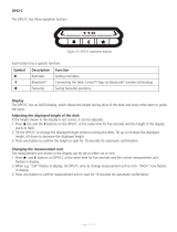
DPG1C
The DPG1C has three operation buttons.
Figure 37: DPG1C operation buttons
Display
The DPG1C has an OLED display, which shows the height during drive of the desk and many other texts to guide
the users.
Adjusting the displayed height of the desk
If the height shown in the display is not correct, it can be adjusted.
1. Press the and the buttons on the DPG1C at the same time for five seconds and the height in the display
starts to flash.
2. Tilt the DPG1C to change the displayed height without moving the desk. Tilt up to increase the displayed
height, tilt down to decrease the displayed height.
3. Press any button to confirm the height or wait for 10 seconds for automatic confirmation.
Changing the measurement unit
The measurement unit shown in the display can be set to either cm or inch.
1. Press and buttons on DPG1C at the same time for five seconds and the current measurement unit
flashes in display.
2. When e.g. “CM” flashes in display, tilt DPG1C once to change measurement unit to inch. “INCH” now flashes
in display.
3. Press any button to confirm measurement unit or wait for 10 seconds for automatic confirmation.
Symbol Description Function
Reminder Setting reminders
Bluetooth®Connecting the Desk ControlTM App via Bluetooth® wireless technology
Favourite Saving favourite positions
Each button has a specific function:

Page 2 of 20
Operate the desk panel by tilting it.
1. Tilt and hold up DPG1C to drive desk up, press and hold down DPG1C to drive desk down.
2. Release DPG1C when you have reached your requested position.
Figure 38: Tilt and hold the DPG1C to drive the desk up Figure 39: Press and hold the DPG1C to drive the desk down
Desk height limits
In case the desk cannot be operated in its entire span (e.g. a shelf is blocking the upwards movement or a filing
cabinet is placed under the desk and blocking the downwards movement), it is possible to set an upper limit and
a lower limit for the desk height.
Note:
It must always be possible to drive the desk to its minimum height in case initialisation is required.
During initialisation items placed under the desk must be removed.
Setting upper limit
1. Adjust desk to maximum allowable height.
2. Press and tilt DPG1C up at the same time for 8 seconds until light flashes.
3. Release and DPG1C.
Setting lower limit
1. Adjust desk to minimum allowable height.
2. Press and press DPG1C down at the same time for 8 seconds until light flashes.
3. Release and DPG1C.

Page 3 of 20
The light strip flashes white two times to indicate that saving the position is in progress. Not until the light strip
becomes static white, has the position been saved. The display indicates the saved position with a and a
position number. The number next to the indicates the order in which the positions are saved.
• First position saved: “1” is displayed next to the .
• Second position saved: “2” is displayed next to the .
Figure 40: Saving favourite positions
Favourite positions
Saving favourite positions 1 and 2
1. Adjust desk to a preferred position.
2. Press button for two seconds.

Page 4 of 20
If the user adjusts the desk to another position and saves this position, it will overwrite the favourite position
(1 or 2) closest to the current position.
Saving favourite positions 3 and 4
1. Press button shortly to make display toggle through the four favourite positions ( with position
number next to it).
2. Toggle through these four favourite positions in display and choose which one to save current position as.
E.g. a user wants to save the current position as favourite position 3:
3. Press the button and toggle to the with “3” next to it.
4. Press button for two seconds and favourite position is saved.
Note:
Favourite positions 3 and 4 can be disabled via the DPG configurator (from DPG SW ver. 1.29).
Driving to favourite positions
After saving the favourite positions, the user can reach the positions simply by tilting/pressing the DPG1C.
1. Tilt/press and hold - when a saved position has been reached, the desk stops.
2. Release DPG1C within one second.
This way the user can easily change between sitting and standing height without looking at the DPG1C in the
meantime. During desk driving, the display will show the height of the desk. When a favourite position has been
reached, the display shows a and the position number.
The DPG1C stops at all saved favourite positions, which means up to four different positions during the stroke
length of the desk.
When the desk stops at a favourite position, the user can
• keep tilting/presssing the DPG1C for more than one second
or
• release the DPG1C and immediately tilt/press it again.
The desk will move past the favourite position and continue its movement.
Figure 41: Tilt/press to drive desk

Page 5 of 20
Automatic driving to favourite positions
(only possible for “Full version” with “Automatic drive” enabled in the Desk ControlTM App)
1. Double-tap DPG1C to let desk adjust automatically to first position in direction of double-tap.
2. To stop driving of desk between two favourite positions, simply tap DPG1C once.
Erasing favourite positions
1. Press the button for eight seconds to erase all saved favourite positions.
After five seconds, the display shows a countdown, and the light strip flashes red when all the favourite
positions are erased.
Figure 42: Double-tap to automatically adjust the desk to a favourite position
Figure 43: Erase favourite positions

Page 6 of 20
Bluetooth®
Connecting Bluetooth®
1. Download Desk Control™ App suited for your device in App store or Google Play.
Search for Desk Control and look for the app icon:
2. Press button in the middle for two seconds to enable pairing mode.
The display on the DPG1C will inform about the Bluetooth® ID of the desk, which is “DESK” followed by a four-
digit number – look for this ID in the list of “Desks nearby” in the Desk ControlTM App.
The light strip flashes blue while the desk panel is in pairing mode.
Figure 44: Connect Bluetooth®

Page 7 of 20
Reminder
The reminder LED lights through the surface of the DPG1C. The light is intended to indicate the position of the
desk (sitting or standing height). The indication depends on the reminder interval chosen.
Heartbeat (light strip)
The heartbeat reminder is shown as a thin LED light strip. While the user is sitting for an appropriate amount of
time according to the set interval, the light strip calmly pulsates green symbolising a heartbeat. When the sitting
interval runs out, the calm pulsating green turns into fast pulsating orange for one minute hereafter into static
orange to indicate that the user should adjust the desk to standing height. In standing height, the light strip
pulsates green until a potential timeout (standard timeout is four hours). When the desk is adjusted back to
sitting height, the light strip pulsates green until the reminder goes off again.
Battery (light blocks)
The battery reminder is shown as three LED light blocks. The LED light blocks are lit differently depending on the
position of the desk.
Sitting:
• During the first third of the set sitting period, three green light blocks are lit symbolising a fully charged battery.
• During the second third of the period, two green light blocks are lit.
• During the last third of the period only one green block is lit.
• When the sitting period runs out, the last green block turns red to indicate that the user should adjust the desk
to standing height.
Standing:
• While the user is standing for the first third of the standing period, one green light block flashes symbolising a
battery being charged.
• During the second third of the period, one green light block is lit and one flashes.
• During the last third of the set period two green blocks are lit and one flashes.
• When the standing period runs out, five green blocks are lit to indicate that the user can adjust the desk to
sitting height.
Reminder restart
The reminder automatically restarts when the desk is adjusted to sitting height.
Reminder timeout
After four hours without any action, the light strip will time out. When the DPG1C is tilted, the green light turns
back on.
When the light (strip or blocks) is enabled for reminders, the DPG1C is no longer in ZERO™ mode as long
as the light is on/active.

Page 8 of 20
Reminder intervals
The number of white blocks (one, two or three) each representing an interval. The three standard intervals are:
- Interval 1: Reminder after 55 minutes sitting
- Interval 2: Reminder after 50 minutes sitting
- Interval 3: Reminder after 45 minutes sitting
The default interval is reminding after 55 minutes, which means one white block lights up.
Adjusting the reminder interval
1. Press button to adjust interval of getting reminded to change position.
2. Toggle through intervals by pressing button.
3. Release button when desired interval is indicated.
When no white blocks are lit up, the reminder is turned off.
Through the app, it is possible to personalise the three intervals to custom values.
Interval 1: Reminder after 55 minutes sitting Interval 2: Reminder after 50 minutes sitting
Interval 3: Reminder after 45 minutes sitting Reminder off
Figure 45: Set the reminder

Page 9 of 20
Resetting the reminder
1. Press symbol for eight seconds to reset reminder to default values.
After five seconds the display shows a countdown and the light strip flashes red when the reminder is reset.
Key lock
The operation of DPG1C can be locked to prevent unintended driving of the desk. As default the key lock is
disabled. If enabled, it automatically locks the DPG1C after a configured amount of time. The key lock function
can also be configured to indicate attempt to operate the locked DPG1C by showing a red light and a .
Unlocking DPG1C
1. Press , and in sequence (max. one second between each button press).
Figure 46: Reset reminder

Page 10 of 20
Factory reset (only DPG1M, DPG1B and DPG1C)
Press and hold the and buttons for eight seconds to set the DPG to factory default. The LED/light strip
flashes red three times to indicate the reset is done. If a factory reset is performed, it sets the DPG back to
the configured state, i.e. all configurations made in the DPG configurator will not be reset – only the settings
changed directly on the DPG or in the app by the end users will be reset.
DPG1C only
During reset, the display lights up after five seconds, showing an arrow with a countdown [seconds] and RESET
Error codes Cause
E53-E64 COLLISION
E41-E52 OVERLOAD
E01 INITIALISATION
Troubleshooting/FAQs
Error codes (only DPG1C)
The DPG1C shows error codes generated in the CBD6S in case of errors in the system. The most common errors
loop between the error code (EXX) and the error text, check the codes below:
Software versions before SW 1.13 only show error E01.
Figure 47: Reset to factory default (DPG1B and DPG1C)
Figure 48: Reset to factory default (DPG1M)

Page 11 of 20
Desk Control™ App
The Desk Control app is developed for users of sit-stand desks. The app allows the users to connect to the desk
via Bluetooth® wireless technology and will now remind the user to use the desk. By downloading the “Desk
Control” app, the desk user comes one step closer to changing the prolonged sitting behaviour and the user gets
the friendly reminder needed to build a healthy routine during the workday. Via the app the desk can also be
adjusted and the user can drive to prestored memory positions. The app comes in 8 languages and is available
for 2 different platforms: iOS for iPhones and iPads and Android for Android smartphones and tablets.
/