Page is loading ...

IC02-3 Data Sheet (NZ329) Page 1Texmate, Inc. Tel. (760) 598-9899 • www.texmate.com
QUADRATURE ENCODER SMART INPUT MODULE
QUADRATURE ENCODER SMART INPUT MODULE
3 Independent
Counter Inputs, A, B & C.
Separate excitation
voltages.
Dual SSR Outputs.
High speed setpoint switching. On-board Digital Signal Processor.
Varied and versatile counter configurations.
2 Independent Frequency
Inputs, A and B.
Input Header.
Header selectable.
mV, TTL and open-collector
transistor options.
Debounce Header.
1 KHz low-pass filter.
With this module you can not only sense position and direction of rotation, but the additional third channel
can be used as the zero signal for precise determination of reference position. A variety of interface
options and excitation voltages are provided to satisfy all user requirements including multiple counter
inputs, a choice of two frequency channels and many interactive modes. When interfaced to the Tiger
320 Series operating system, these powerful software features provide the solution to all your counting
needs in process control applications.
The total solution to incremental shaft encoder control
Fits Tiger 320 Series
Smart UP/DOWN
Counter
Multi Counter
Optional Dual High-
speed S.S.R. Output
Interface to Tiger Meter
RPM, Pulse, Counter
Hardware Module Specifications
Software Module Features
Counter Inputs 3 independent hardware counters.
Input Header Configured for mV, TTL, O.C (npn)
or O.C (pnp) interface. Switching speed typically 20 kHz,
operating mode dependent. (See Table 1).
Excitation Voltage 24 Vdc (50 mA maximum) available for all counter inputs.
SSRs Dual, setpoint switching, solid-state relays.
17 Ω output impedance, ± 400 V isolation,
140 mA maximum load current.
Debounce Header Set to OFF position for high-speed encoding. Set to ON
position for 1 kHz low-pass filter
useful in contact push-button debounce inputs.
Quadrature Mode Choice of x1, x2 and x4 modes for increased resolution.
A, B Modes A & B independent counter inputs arranged in various
combinations.
C Mode C counter control to capture, reset to predetermined
counts, zero and/or restart A & B counters.
SSR Switching Independent fast >1 ms setpoint switching of each SSR using
counter selected from smart output register.
Can be NO or NC relay outputs.
Frequency Option 100 kHz on A input, 500 kHz on B input.
Some Relevant Tiger 320 Series Operating System Features
Dual Rate (Frequency) 0n A and B.
Setpoint Timer Functions.
Setpoint Register Reset and Trigger Functions.
Macro Compiler for PLC Functions.
INPUTS
IC02 (No SSR)
IC03 (with 2 SSRs)
Input Module
Order Code Suffix

Texmate, Inc. Tel. (760) 598-9899 • www.texmate.comPage 2 IC02-3 Data Sheet (NZ329)
234H
Signal A
CH1
ON
Debounce
Headers
Input
Headers
OFF
1
2
3
4
CH 2 CH 3
Signal B
Signal C
EXC
GND
COMMON SSR1, SSR2
QUADRATURE ENCODER (speed & direction)
Phase (A)
Phase (B)
Index / Marker
Supply
Ground
NORMALLY OPEN SSR2
NORMALLY OPEN SSR1
PIN 1
PIN 2
PIN 3
PIN 4
PIN 5
PIN 6
PIN 7
PIN 8
mV 1
TTL 2
PNP 3
NPN 4
Smart Register 1
Smart register 1 allows you to select either the quadrature, combined, or independent counting mode for input signals A and B. Input
signal C is the control mode for input signals A and B to capture, gate, zero, reset, or start the counters and is also selected through
smart register 1. Input signal C can also be set as an independent counter without control o ver input signals A and B.
The resultant count produced by each mode is stored in the smar t register output map in primary, secondary, capture or gate coun-
ters. Any of the counters can be tr ansferred to Channel 1 via Code 2, to Channel 2 via Code 4, to Channel 3 via Code 5, and to
Channel 4 via Code 6.
Smart Register 2 (IC03 Only)
Smart register 2 allows you to select the setpoint control settings of smar t relay 1 (SR1) and smar t relay 2 (SR2) using either the
primary, secondary, capture, or gate counters of the smar t register 2 output map . All other settings f or SR1 are configured via set-
point 5 and for SR2 via setpoint 6 in the meter ’s setpoint programming mode.
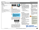
Connector Pinouts
Figure 1 – IC03 Smar t Input Module Wired to a Quadrature Encoder
The interface header s ha ve
been set to NPN input, the
debounce header s are in the
OFF position, and the encoder
takes its e xcitation v oltage
directly from IC03.
Detailed Description
Smart Setup Registers
The meter has three smart setup registers to configure smart input modules. Smart input module IC02 requires only smart register
1to be set up , while IC03 requires smart registers 1 and 2 to be set up . Figure 2 shows the functions of quadr ature smart input
modules IC02 and IC03 with input signals from a standard quadr ature encoder.
Figure 2 – IC02 & IC03 Quadrature Smar t Setup Registers – Operational Flow Diagram
Signal A CODE 2 SMART REGISTER 1 SETUP REGISTER OUTPUT MAP
Enter Code 2.
Select smart register 1
setup [X77].
This allo ws y ou to enter
smart register 1 setup
and configure settings for
input signals A, B, & C.
Select all relevant settings for input signals A, B, & C.The register output map allo ws y ou
to select a specific output f or a
selected channel.
CH1
CH2
CH3
CH4
CODE 5 SMART REGISTER 2 SETUP
Enter Code 5.
Select smart register 2
setup [X77].
This allows you to enter
smart register 2 setup
and configure settings
for setpoint 5 (SP5)
and setpoint 6 (SP6).
Select all relevant settings for SP5 and SP6.
SMART REGISTER 3 SETUP
Not required.
A&B SIGNALS FUNCTIONS
0 Quadrature x 1
1 Quadrature x 2
2 Quadrature x 4
3 A + B Count
4A – B Count
5 A, B Independent Count
6 A Count, B Direction
7-
SECOND DIGIT
C SIGNAL FUNCTIONS
0 No Function
1 Capture A, B
2 Gate Count A, B
3 Gate Count & Reset A, B
4 Reset to Offset & Start A, B
5 C Count
6 Reset to Offset A, B
7-
THIRD DIGIT
Signal B
Signal C
SMART REGISTER 1 OUTPUT MAP
0 PRIMARY Counter
1 SECONDARY Counter
2 PRIMARY Capture
3 SECONDARY Capture
4 Gate PRIMARY Counter
5 Gate SECONDARY Counter
6-
7 Smart input module register 1
code setup
THIRD DIGIT
IC02 & IC03
IC03 Only
FIRST DIGIT
SMART RELAY OUTPUT MODE
SECOND DIGIT
SP6 SOURCE SP5 SOURCE
0 PRIMARY Counter
1 SECONDARY Counter
2 PRIMARY Capture
3 SECONDARY Capture
4 Gate PRIMARY Counter
5 Gate SECONDARY Counter
6-
7-
THIRD DIGIT
0 SR1 & SR2 NO
1 SR1 NC, SR2 NO
2 SR1 NO, SR2 NC
3 SR1 & SR2 NC
0 PRIMARY Counter
1 SECONDARY Counter
2 PRIMARY Capture
3 SECONDARY Capture
4 Gate PRIMARY Counter
5 Gate SECONDARY Counter
6-
7-
Note: Settings for the 1st digit are not rele vant
PRIMARY Counter
SECONDARY Counter
PRIMARY Capture
SECONDARY Capture
Gate PRIMARY Counter
Gate SECONDARY Counter

IC02-3 Data Sheet (NZ329) Page 3Texmate, Inc. Tel. (760) 598-9899 • www.texmate.com
Counter Functions
Counter inputs A, B, and C can be portrayed as a train of pulses having a rising edge ( ) and falling edge ( ) between a low
and high signal level. Depending on the counter function selected, these inputs may vary in phase to each other. In the case of a shaft
encoder, the Asignal lags the Bsignal by 90°and the primary counter decrements when the shaft is rotated clockwise. To change the
direction of rotation to countercloc kwise, reverse the A and B signal inputs at the connector (see Figure 1). The Csignal occurs once
per revolution.
See Figure 3.
OR
OR
A
B
C
Pulse Train Direction
Signal
Signal
Signal
With A and B signals 90° out-of-phase
Phase (A)
Phase (B)
Index/Marker
Figure 3 – Counter Input Signals
A and B Signal Functions
Quadrature Modes
The quadrature modes are shown for a shaft encoder as an example. Depending on the direction of rotation, the Asignal leads or lags
the Bsignal.
Using the same shaft encoder, the angular / linear resolution of the x1 Mode can be increased b y 2 using the x2 Mode , or by 4 using
the x4 Mode.
x1 Mode
This is the most commonly used counter function and oper ates as follows:
See Figures 4 and 5.
Direction of rotation: Clockwise
•The primary counter decrements on a rising
edge ( ) Asignal when Bis low.
Figure 4 – x1 Mode: Primary Counter
Decrements
Table 1 lists the counter functions a vailable and the maximum
input frequency for each mode.
Counter Mode
Quadrature x1 ......................................................
Quadrature x2 ......................................................
Quadrature x4 ......................................................
A+B .......................................................................
A–B .......................................................................
A, B Independent ................................................
A Count, B Direction ...........................................
Capture A, B ........................................................
Gate Count A, B ..................................................
Gate Count Reset A, B ........................................
Reset to Offset & Star t A, B ...............................
C Count ................................................................
Reset to Offset A, B ............................................
20 kHz
20 kHz
10 kHz
10 kHz
10 kHz
10 kHz
10 kHz
10 kHz
10 kHz
10 kHz
10 kHz
38 kHz
10 kHz
Max. Frequency for A, B & C Inputs
Table 1 Counter Modes Switching Speeds
A
B
Pulse Train Direction
Signal
Signal
With A and B signals 90° out-of-phase
Primary
Counter
Counterclockwise
Figure 5 – x1 Mode: Primary Counter
Increments
Direction of rotation: Counterclockwise
•The primary counter increments on a falling
edge ( ) Asignal when Bis low.
A
B
Pulse Train Direction
Signal
Signal
With A and B signals 90° out-of-phase
Primary
Counter
Clockwise

Texmate, Inc. Tel. (760) 598-9899 • www.texmate.comPage 4 IC02-3 Data Sheet (NZ329)
x4 Mode
The x4 mode operates as follows:
See Figures 8 and 9.
Direction of rotation: Clockwise
•The primary counter decrements on a rising
edge ( ) Asignal when Bis low.
•The primary counter decrements on a rising
edge ( ) Bsignal when Ais high.
•The primary counter decrements on a falling
edge ( ) Asignal when Bis high.
•The primary counter decrements on a falling
edge ( ) Bsignal when Ais low.
There is no fix ed relationship betw een A and B . Signal A increments the pr imary
counter on every rising edge. Signal B increments the primary counter on every ris-
ing edge.
The A+B signal count mode oper ates as follows:
See Figure 10.
•The primary counter increments on a rising edge ( ) Asignal.
•The primary counter increments on a rising edge ( ) Bsignal.
OR
OR
Direction of rotation: Counterclockwise
•The primary counter increments on a rising
edge ( ) Asignal when Bis high.
•The primary counter increments on a rising
edge ( ) Bsignal when Ais low.
•The primary counter increments on a falling
edge ( ) Asignal when Bis low.
•The primary counter increments on a falling
edge ( ) Bsignal when Ais high.
A
B
Signal
Signal
Primary
Counter
OR
A
B
Signal
Signal
Primary
Counter
Figure 10 – A+B Signal Count Mode:
Primary Counter Increments
Application:
You may have two production lines in a factory with a sensor on each line. By adding the totals
of each counter you can determine the total output of the f actory.
A+B Signal Count Mode (Anticoincident)
x2 Mode
The x2 mode operates as follows:
See Figures 6 and 7.
Direction of rotation: Clockwise
•The primary counter decrements on a rising
edge ( ) Asignal when Bis low.
•The primary counter decrements on a
falling edge ( ) Asignal when Bis high.
Direction of rotation: Counterclockwise
•The primary counter increments on a rising
edge( ) Asignal when Bis high.
•The primary counter increments on a falling
edge ( ) Asignal when Bis low.
A
B
Pulse Train Direction
Signal
Signal
With A and B signals 90° out-of-phase
Primary
Counter
Clockwise
Figure 6 – x2 Mode: Primary Counter
Decrements
A
B
Pulse Train Direction
Signal
Signal
With A and B signals 90° out-of-phase
Primary
Counter
Counterclockwise
Figure 7 – x2 Mode: Primary Counter
Increments
A
B
Pulse Train Direction
Signal
Signal
With A and B signals 90° out-of-phase
Primary
Counter
Clockwise
Figure 8 – x4 Mode: Primary Counter
Decrements
A
B
Pulse Train Direction
Signal
Signal
With A and B signals 90° out-of-phase
Primary
Counter
Counterclockwise
Figure 9 – x4 Mode: Primary Counter
Increments

IC02-3 Data Sheet (NZ329) Page 5Texmate, Inc. Tel. (760) 598-9899 • www.texmate.com
The A and B signals are link ed in a phase relationship . Signal A
increments the pr imary counter on e very rising edge, while signal B
decrements the primary counter on every rising edge.
The A–B signal count mode operates as follows:
See Figure 11.
•The primary counter increments on a rising edge ( ) Asignal.
•The primary counter decrements on a rising edge ( ) Bsignal.
OR
OR
Primary
Counter
Primary
Counter
A
B
Signal
Signal
OR
A
B
Signal
Signal
Primary
Counter
Primary
Counter
Figure 11 – A–B Signal Count Mode: Primary
Counter Increments/Decrements
Application:
This mode is useful when the diff erence betw een tw o counts is
required. For example, a carpark building where the A signal rep-
resents an incoming car and the B signal represents an outgoing
car. A minus B lets you know how many cars are in the building at
any one time.
A–B Signal Count Mode (Anticoincident)
A&B Independent Mode (Anticoincident)
There is no fixed relationship between signals A and B. Signal A increments the primary counter on every rising edge. Signal B incre-
ments the secondary counter on every rising edge.
The A&B independent mode operates as follows:
See Figure 12.
A
B
Signal
Signal
Primary
Counter
Secondary
Counter
OR Primary
Counter
OR Secondary
Counter
Figure 12 – A&B Independent Mode: Primary Counter
Increments, Secondary Counter Increments
•The primary counter increments on a rising edge ( ) A
signal.
•The secondary counter increments on a rising edge ( )
Bsignal.
OR
OR
Application:
This mode is useful for dual counting systems.
A
B
Signal
Signal
Primary
Counter OR Primary
Counter
Figure 14 – A Count, B Direction Mode: Primary Counter
Decrements
•The primary counter
decrements on a ris-
ing edge ( ) A
signal when Bis
high.
OR
A
B
Signal
Signal
Primary
Counter
Primary
Counter
OR
Figure 13 – A Count, B Direction Mode: Primary Counter
Increments
A Count, B Direction Mode
The A and B signals are link ed in a phase relationship. Signal A increments the pr imary counter on every rising edge when signal B is
low. Signal A also decrements the pr imary counter on every rising edge when signal B is high.
The A count, B direction mode oper ates as follows:
See Figures 13 and 14.
•The primary counter
increments on a ris-
ing edge ( ) A
signal when Bis low.
OR
Application:
Some positional encoders have this type of output instead of a quadr ature output.

Texmate, Inc. Tel. (760) 598-9899 • www.texmate.comPage 6 IC02-3 Data Sheet (NZ329)
•The primary counter value is
loaded into primary capture on a
falling edge ( ) Csignal.
•The secondary counter value is
loaded into secondary capture
on a falling edge ( ) Csignal.
O
C Signal Functions
Csignal functions operate with the Aand Bsignal functions and influence the pr imary and secondary gate and capture counters.
Capture A, B Mode
The capture A, B mode provides a snapshot of the pr imary and secondary counters. It is a straight transfer of the values from the pri-
mary and secondary counters to primary and secondary capture.
See Figure 15.
C
Signal
Primary
Counter
Primary
Capture
Loading to
Secondary
Counter
Secondary
Capture
Loading to
Figure 15 – Capture A, B Mode
Application:
This mode is useful to capture positional inf ormation in relation to an e xternal event. To track if an y errors occur , the positi onal
information could be used as a ref erence that the encoder can be compared against.
Note:
The primary and secondary counters are not affected by the operation and no counts are lost.
Gate Count A, B
In this mode the primary and secondary gate counters are updated with the number of pulses that occur in the primary (A signal) and
secondary (B signal) counters respectively between consecutive falling edge C signal pulses. The primary and secondary counters are
not reset and continue to count after each update of the gate counters . The gate count A, B mode oper ates as follows:
See Figure 16.
•The value in the primary counter on the pre vious falling edge ( ) Csignal is subtr acted from the v alue in the primary counter on the
most recent falling edge ( ) Csignal and loaded into the primary gate counter. The primary counter continues to count up and is not
reset after each event.
•The value in the secondary counter on the previous falling edge ( ) Csignal is subtracted from the value in the secondary counter on
the most recent falling edge ( ) Csignal and loaded into the secondary gate counter. The secondary counter continues to count up
and is not reset after each e vent.
Note:
The gate secondary counter is only updated in the A & B independent mode .
Application:
This mode is
useful to capture
rate inf ormation
in relation to an
external e vent.
For e xample,
you may want to
know ho w m uch
product was pro-
duced per shift.
At the star t of
the shift, the
operator could
set a s witch and
reset it at the
end of the shift.
The resultant
gate counter
would let y ou
know ho w m uch
was produced
during that shift. Figure 16 – Snapshot of Gate Count A, B Mode: Primary Counter
A
C
Signal
Signal
P1 P2 P3 P4
400 pulses
600 pulses
1100 pulses
1800 pulses
B
Signal
S1 S2 S3 S4
500 pulses
800 pulses
1400 pulses
2300 pulses
Primary Gate
Counter
Constantly updated
with pulses occuring
between falling edge
C signals
P2 – P1 = 200 pulses
P3 – P2 = 500 pulses
P4 – P3 = 700 pulses
P5 ..................
Primary
Counter
Constantly
Counting
Primary
Counter
Secondary
Counter
Secondary Gate
Counter
Constantly updated
with pulses occuring
between falling edge
C signals
S2 – S1 = 300 pulses
S3 – S2 = 600 pulses
S4 – S3 = 900 pulses
S5 ..................
Secondary
Counter
Constantly
Counting

IC02-3 Data Sheet (NZ329) Page 7Texmate, Inc. Tel. (760) 598-9899 • www.texmate.com
Gate Count & Reset A, B Mode
In this mode the pr imary and secondary gate counters are again updated with the n umber of pulses that occur in the pr imary (A sig-
nal) and secondar y (B signal) counters respectiv ely between consecutive falling edge C signal pulses . But, in this case , the pr imary
and secondary counters are reset after each update of the gate counters . The gate count & reset mode oper ates as follows:
See Figure 17.
•The value in the primary counter on the pre vious falling edge ( ) Csignal is subtr acted from the v alue in the primary counter on the
most recent falling edge ( ) Csignal and loaded into the primary gate counter. The primary counter stops counting after each f alling
edge C signal event and is reset to 0.
•The value in the secondary counter on the previous falling edge ( ) Csignal is subtracted from the value in the secondary counter on
the most recent falling edge ( ) Csignal and loaded into the secondary gate counter. The secondary counter stops counting after each
falling edge C signal event and is reset to 0.
O
Figure 17 – Snapshot of Gate Count & Reset Mode
A
C
Signal
Signal
P1 P2 P3 P4
400 pulses 200 pulses 500 pulses 700 pulses
B
Signal
S1 S2 S3 S4
500 pulses 300 pulses 600 pulses 900 pulses
Primary Gate
Counter
Constantly updated
with pulses occuring
between falling edge
C signals
P2 – P1 = –200 pulses
P3 – P2 = 300 pulses
P4 – P3 = 200 pulses
P5 ..................
Primary
Counter
Resets after
C signal
Primary
Counter
Secondary
Counter
Secondary Gate
Counter
Constantly updated
with pulses occuring
between falling edge
C signals
S2 – S1 = –200 pulses
S3 – S2 = 300 pulses
S4 – S3 = 300 pulses
S5 ..................
Secondary
Counter
Resets after
C signal
Reset to Offset & Start A, B Mode
In this mode the primary and secondary counters are reset to the value stored in the meter’s primary and secondary reset offset reg-
isters (registers 121 and 122 respectively). Primary and secondary counters continue counting after being reset to the reset offset val-
ues.
The reset to offset & star t A, B mode oper ates as follows:
See Figure 18.
C
Signal
Primary
Reset
Offset
Register
Primary
Counter
Secondary
Counter
Secondary
Reset
Offset
Register
Reset
Reset
Begin Counting
Begin Counting
(Reset to value in
Secondary Reset
Offset Register)
(Reset to value
in Primary Reset
Offset Register)
Figure 18 – Reset to Offset & Star t Mode
•The pr imary and secondar y coun-
ters begin counting on a rising
edge ( ) Csignal.
•On a falling edge ( ) Csignal the
primary counter is reset to the
value stored in the primary reset
offset register (121) , and the sec-
ondary counter reset to the v alue
stored in the secondary reset off-
set register (122).
The default setting of the pr imary and secondary reset offset registers is 0. To change the value stored in these registers:
•Connect the meter to a PC r unning a terminal program.
•Start the terminal program.
•Access register 121 and change the offset to the required v alue.
•Access register 122 and change the offset to the required v alue.
See Registers Supplement (NZ209), Registers 121 and 122 – Reset Offset Registers, for a detailed description of the reset offset reg-
isters.

Texmate, Inc. Tel. (760) 598-9899 • www.texmate.comPage 8 IC02-3 Data Sheet (NZ329)
Programming Quick Start Guide
2
3
1
Programming Procedures
A&B SIGNALS FUNCTIONS
0 Quadrature x 1
1 Quadrature x 2
2 Quadrature x 4
3 A + B Count
4A – B Count
5 A, B Independent Count
6 A Count, B Direction
7-
SECOND DIGIT
C SIGNALS FUNCTIONS
0 No Function
1 Capture A, B
2 Gate Count A, B
3 Gate Count & Reset A, B
4 Reset to Offset & Start A, B
5 C Count
6 Reset to Offset A, B
7-
THIRD DIGIT
FIRST DIGIT
This setting enters the smart register 1
code setup menu.
This men u pro vides settings unique to
smart register 1 of the IC02/IC03 input
module.
Press the and buttons at the same time to enter the main prog ramming mode.
P
Press the button.
P
Note the register map is
different for each smar t
input module type.
Press the button three times to enter Code 2. Set Code 2 to [X77].
P
Using the buttons,
select the function f or the A & B inputs
and the function for the C input.
4
Not Relevant
Note, see Detailed Description on P age 3 f or a
description of A, B, and C counter functions.
C Count Mode
In this mode the primary counter increments on a rising edge ( ) Csignal only.
See Figure 19.
Application:
This mode is useful f or when an e xternal reset is required. For example, A pushbutton on the C input can be used to reset to 0,
or forward the counter to a known count. The counter starts again when the b utton is released.
C
Signal
Primary
Counter
(Increments)
Figure 19 – C Count Mode
Application:
This mode is useful for multi-input systems.
C
Signal
Index/Marker
Primary
Reset
Offset
Register
Primary
Counter
Secondary
Counter
Secondary
Reset
Offset
Register
(Continues counting
after being reset to
value in Secondary
Reset Offset Register)
(Continues counting
after being reset to
value in Primary
Reset Offset Register)
Reset
Reset
Figure 20 – Reset to Offset A, B Mode
Reset to Offset A, B Mode
In this mode the primary and secondary counters are also reset to the value stored in the meter’s primary and secondary reset offset
registers (registers 121 and 122 respectiv ely). But, in this mode , the pr imary and secondar y counters contin ue counting after be ing
reset to the reset offset v alues.
See Figure 20.
The reset to offset A, B mode oper ates as follows:
•On a falling edge ( ) Csignal the primary counter is reset to
the value stored in the primary reset offset register (121), and
the secondary counter reset to the value stored in the second-
ary reset offset register (122) .
•The pr imary and secondar y counters contin ue to count on
being reset.
O
Application:
This mode is useful for setting a position to a known reference position. For example, a microswitch can be positioned at ‘home’ and
used as an input to C on a milling tab le. Now every time the ‘home’ position is encountered, the counter is set to a kno wn position.
MEASUREMENT TASK
0 Voltage, Current
1 TC (3rd digit selects type of TC)
2 RTD 3-wire (3rd digit selects type
of RTD)
3 RTD 2- or 4-wire (3rd digit selects
type of RTD)
4 Frequency
5Period
6 Counter
7 Smart Input Module
SECOND DIGITFIRST DIGIT
SMART REGISTER 1 OUTPUT MAP
0 PRIMARY Counter
1 SECONDARY Counter
2 PRIMARY Capture
3 SECONDARY Capture
4 Gate PRIMARY Counter
5 Gate SECONDARY Counter
6-
7 Smart input module register 1
code setup
THIRD DIGIT
0 10 Hz
1 10 Hz
2 100 Hz
3 100 Hz
TIGER PROCESSING RATE

IC02-3 Data Sheet (NZ329) Page 9Texmate, Inc. Tel. (760) 598-9899 • www.texmate.com
Press the button 3 times to enter Code 5. Set Code 5 to [X77].
P
7
8
Note the register map is diff erent for
each smart input module type.
This setting enters the smart register 2
code setup menu.
Press the button.
P
MEASUREMENT TASK
0 No function
1 Voltage, current
2TC
3RTD
4 Real-time clock & timer
5-
6-
7 Smart input module
SECOND DIGITFIRST DIGIT
SMART REGISTER 2 OUTPUT MAP
0 PRIMARY Counter
1 SECONDARY Counter
2 PRIMARY Capture
3 SECONDARY Capture
4 Gate PRIMARY Counter
5 Gate SECONDARY Counter
6-
7 Smart input module register 2
code setup
THIRD DIGIT
0 Direct Displa y of Input (no
processing)
1 Square Root of Channel 3
2 Inverse of Channel 3
3Meters with 4 kB memor y
NO Linearization
Meters with 32 kB memory
32-point Linear ization of
CH3 using Table 3
Note:
All linear ization tab les are
set up in the Calibr ation
Mode [24X].
TIGER PROCESSING RATE
5Press the button. The display returns to [Cod_2] [X77].
P
6Using the button, reset the 3rd digit to z ero [X70] to leave the smart register 1 menu.
Note, leaving the 3rd digit as 7 means the displa y constantly cycles between [Cod_2] and [SMt1].
Using the button, reset the 3rd digit to 0 to lea ve the smart register 2 menu.
Press the button to save the settings.
P
The display toggles between [Cod_5] and [X77].
Press the and button at the same time to retur n to the operational display.
P
12
FIRST DIGIT
This men u pro vides settings unique to
smart register 2 of the IC02/IC03 input
module.
SMART RELAY OUTPUT MODE
SECOND DIGIT
SP6 SOURCE
Select the setpoint source for switching from the smart output registers for SP5 in the 3rd digit and
SP6 in the 2nd digit, and the operating mode of the solid state relays SR1 and SR2 in the 1st digit.
9
10
11
SP5 SOURCE
0 PRIMARY Counter
1 SECONDARY Counter
2 PRIMARY Capture
3 SECONDARY Capture
4 Gate PRIMARY Counter
5 Gate SECONDARY Counter
6-
7-
THIRD DIGIT
0 SR1 & SR2 NO
1 SR1 NC, SR2 NO
2 SR1 NO, SR2 NC
3 SR1 & SR2 NC
0 PRIMARY Counter
1 SECONDARY Counter
2 PRIMARY Capture
3 SECONDARY Capture
4 Gate PRIMARY Counter
5 Gate SECONDARY Counter
6-
7-
Press the and button at the same time again to re-enter the main prog ramming mode.
P
13
Press the button three times to enter Code 2.
P
14
Select a Channel Select the output register for the required channels
Note the register
map is diff erent for
each smar t input
module type.
CH1
Set Code 2 to [X7X]. Select the required processing rate for CH1 in the 1st digit and the required
register map settings in the 3rd digit.
15
SMART REGISTER OUTPUT MAP
0 PRIMARY Counter
1 SECONDARY Counter
2 PRIMARY Capture
3 SECONDARY Capture
4 Gate PRIMARY Counter
5 Gate SECONDARY Counter
6-
7 Smart input module register code
setup
THIRD DIGIT
FIRST DIGIT
0 10 Hz
1 10 Hz
2 100 Hz
3 100 Hz
TIGER PROCESSING RATE

Texmate, Inc. Tel. (760) 598-9899 • www.texmate.comPage 10 IC02-3 Data Sheet (NZ329)
Note, to measure frequenc y
on A and B inputs select the
appropriate options in Code 2
and Code 4 respectively.
CH2
Set Code 4 to [0X0]. Select the required register map settings for CH2 in the 2nd digit.
16
MEASUREMENT TASK
0 Voltage, Current
1 TC (type as per 2nd digit)
2 RTD (type as per 2nd digit)
3 Second Digital Input
Channel (type as per 2nd
digit)
FOR VOLTAGE & CURRENT
0 Channel 2 Disabled
1 Direct (no post processing)
2 Square Root of Channel 2
3 Inverse of Channel 2
4 Output Register 1 (smart module)*
5 Output Register 2 (smart module)*
6 Output Register 3 (smart module)*
7 Output Register 4 (smart module)*
SECOND DIGITFIRST DIGIT
*Note:
The logic f or CH2 is not the same as
CH1, CH3, or CH4. The 1st and 3rd
digits must both be set to 0. Selecting
040 to 070 in the 2nd digit of Code 4
directly selects one of the f ollowing
settings in the register output map
(3rd digit):
4 selects
5 selects
6 selects
7 selects
2nd Digit Register Output Map
0 PRIMARY Counter
1 SECONDARY Counter
2 PRIMARY Capture
3 SECONDARY Capture
Press the and buttons at the same
time to return to the operational display.
P
Press the button to save the settings.
P
CH3
CH4
If required enter Code 5 and select the required register map settings for CH3 in the 3rd digit.
If required enter Code 6 and select the required register map settings for CH4 in the 3rd digit.
17
18
19
FIRST DIGIT
0 Direct Display of Input (no processing)
1 Square Root of Channel 4
2 Inverse of Channel 4
3Meters with 4 kB memor y
NO Linearization
Meters with 32 kB memor y
32-point Linear ization of CH4 using
Ta bl e 4
Note:
All linear ization tab les are set up in
the Calibration Mode [24X].
CH4 POST PROCESSING
Note the register map is
different for each smart
input module type.
SMART REGISTER 1 OUTPUT MAP
0 PRIMARY Counter
1 SECONDARY Counter
2 PRIMARY Capture
3 SECONDARY Capture
4 Gate PRIMARY Counter
5 Gate SECONDARY Counter
6-
7 Smart input module register 1
code setup
THIRD DIGIT
FIRST DIGIT
0 Direct Display of Input (no processing)
1 Square Root of Channel 3
2 Inverse of Channel 3
3Meters with 4 kB memor y
NO Linearization
Meters with 32 kB memor y
32-point Linear ization of CH3 using
Ta bl e 3
Note:
All linear ization tab les are set up in
the Calibration Mode [24X].
CH3 POST PROCESSING
Customer Configuration Settings:
1st Digit 2nd Digit 3rd Digit
1st Digit 2nd Digit 3rd Digit
CH3
CH4
CH2
1st Digit 2nd Digit 3rd Digit
1st Digit 2nd Digit 3rd Digit
1st Digit 2nd Digit 3rd Digit
1st Digit 2nd Digit 3rd Digit
CH1
7
7
7
00

IC02-3 Data Sheet (NZ329) Page 11Texmate, Inc. Tel. (760) 598-9899 • www.texmate.com
perates an automatic cut-to-len
g
th
g
uillotine. A
Texmate 320 Ser ies prog rammable meter controller has been
installed and prog rammed to measure length from an encoder
input. Setpoint 1 is prog rammed to oper ate at the required cut-
off length. A clutch and a clamp oper ate to stop the metal f eed
motor.
t
o Len
g
th Controller
21
APPLICATION VARIATIONS
• A total number of cuts can be programmed to SHUT OFF
the guillotine at the required total.
OPERATIONAL DISPLAY
displays length
Feed
Motor
Encoder
Start/Stop
Press Control
SP1 SP2 SP3 SP4 SP5 SP6
Prog.
inch
DI-50 Tiger 320 Series
After a prog rammed OFF-time , (to enab le the guillotine to
complete its cut cycle) the displayed length is reset to 0.
The clamp releases , the clutch engages , and the metal
commences feeding, repeating the process. At each cut-off, 1 is
added to a totalizer. (Viewed by pressing the UP button.)
CUT TO LENGTH CONTROLLER
FREQUENCY
RELAY
OUTPUTS
TIMERS
TOTALIZERS
SEQUENCE
CONTROLS
APPLICATION
FUNCTIONS
INPUTS

Texmate, Inc. Tel. (760) 598-9899 • www.texmate.comPage 12 IC02-3 Data Sheet (NZ329)
CODE 2
Example Quadrature Encoder with Setpoint Contr ol Setup Procedure
Our customer operates a steel punch and wishes to automate the process using a rotar y encoder. Texmate installed a Tiger 320
Series DI-50 meter with an IC03 quadr ature encoder smart input module.
The encoder is used to set the length of steel plate being punched. The metal punch is activated using the module’s smart relay
output SR1.
The primary counter is read b y channel 1 and configured in the x1 quadr ature mode. This setting provides 1 to 1 encoder reso-
lution. Setpoint 5 is configured to activate SR1 from the pr imary counter.
3
1Select the encoder resolution quadrature x1 for the A & B counter functions
in the 3rd digit, and no function for the C counter function in the 2nd digit:
In select X77 then press button.
P
SMt1 000
Set X00
Set setpoint 5 (SP5) sour ce to the primar y counter
with SR1 switch closure set to normally open (NO):
CODE 5
In select X77
Display toggles between
SMt1 to
CODE 2
2Select the primary counter for CH1:
In select X70
SMt2 000
Set 0X0
Display toggles between
SMt2 to
then press button.
P
Note, in the quadrature mode the primar y
counter is always used to output positional
count and direction of rotation.
OPERATIONAL DISPLAY
displays length
Feed
Motor
Encoder
Start/Stop
Press Control
SP1 SP2 SP3 SP4 SP5 SP6
Prog.
inch
DI-50 Tiger 320 Series
CUT TO LENGTH CONTROLLER
WARRANTY
Texmate warrants that its products are free from def ects in mater ial and w orkmanship under
normal use and ser vice for a per iod of one y ear from date of shipment. Texmate’s obligations
under this warranty are limited to replacement or repair, at its option, at its factory, of any of the
products which shall, within the applicable period after shipment, be returned to Texmate’s facil-
ity, tr ansportation charges pre-paid, and which are , after e xamination, disclosed to the satis-
faction of Texmate to be thus def ective. The warranty shall not apply to an y equipment which
shall have been repaired or altered, except by Texmate, or which shall have been subjected to
misuse, negligence , or accident. In no case shall Texmate’s liability e xceed the or iginal pur-
chase price. The aforementioned provisions do not e xtend the or iginal warranty period of any
product which has been either repaired or replaced b y Texmate.
USER’S RESPONSIBILITY
We are pleased to offer suggestions on the use of our v arious products either by way of print-
ed matter or through direct contact with our sales/application engineering staff. However, since
we ha ve no control o ver the use of our products once the y are shipped, NO WARRANTY
WHETHER OF MERCHANT ABILITY, FITNESS FOR PURPOSE, OR O THERWISE is made
beyond the repair, replacement, or refund of purchase pr ice at the sole discretion of Texmate.
Users shall deter mine the suitability of the product f or the intended application bef ore using,
and the users assume all risk and liability whatsoever in connection therewith, regardless of any
of our suggestions or statements as to application or constr uction. In no event shall Texmate’s
liability, in law or otherwise, be in excess of the purchase pr ice of the product.
Texmate cannot assume responsibility for any circuitry described. No circuit patent or software
licenses are implied. Texmate reserves the right to change circuitry, operating software, speci-
fications, and prices without notice at any time.
Tel: 1-760-598-9899 • USA 1-800-839-6283 • That’s 1-800-TEXMATE
Email: [email protected] • Web: www.texmate.com
1934 Kellogg Ave. • Carlsbad, CA 92008
/