Page is loading ...

OPERATOR MANUAL
Amsco® CenturyTM
Medium Steam Sterilizers 660 x 950 mm
• Prevacuum
(REV AD) P129373-476


i
Table of Contents Operator Manual 129373-476
A WORD FROM STERIS CORPORATION
This manual contains important information on proper use of this sterilizer.
All operators and department heads must carefully review and become
familiar with the warnings, cautions and instructions contained in this
manual.
These instructions are important to the health and safety of
personnel operating the sterilizer and should be retained in a conveniently
accessible area for quick reference.
This sterilizer is specifically designed to process goods using only the
cycles as specified in this manual. If there is any doubt about a specific
material or product, contact the manufacturer of the product for the
recommended sterilization technique.
STERIS carries a complete line of accessories for this unit to simplify,
organize and assure sterility of the sterilization process. Instrument trays,
pouches and biological/chemical monitoring systems are all available to
fulfill your facility’s processing needs. A STERIS representative will gladly
review these with you.
A thorough preventive maintenance program is essential to safe and proper
sterilizer operation. You are encouraged to contact STERIS concerning our
Preventive Maintenance Agreement. Under terms of this agreement, pre-
ventive maintenance, adjustments, and replacement of worn parts are done
on a scheduled basis to assure equipment performance at peak capability
and to help avoid untimely or costly interruptions. STERIS maintains a
worldwide staff of well-equipped, factory-trained technicians to provide this
service, as well as expert repair services. Contact your STERIS represen-
tative for details.
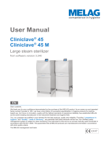
The Amsco® CenturyTM Medium Steam Sterilizer 660 x 950 mm is a prevacuum
unit designed for sterilization of heat- and moisture-stable materials used in
healthcare facilities. It is equipped with Prevacuum, Gravity, Liquid, Leak
Test and Bowie-Dick cycles.
Indications for Use
(Continued on following page.)
Service Information
© 2019 – STERIS Corporation. All rights reserved. Printed in U.S.A.

ii
129373-476 Operator Manual Table of Contents
Table 1. Factory-Set Cycles and Cycle Values
The Amsco Century Medium Steam Sterilizer 660 x 950 mm is equipped with the following factory programmed
sterilization cycles and cycle values (Table 1A).
Cycles: Sterilize Sterilize Dry Recommended Validation
Temp. Time Time Load Standard
1. PREVAC
134°C (273°F) 3-1/2 MIN. 30 MIN. Instrument Trays, Fabric Packs EN-285
Refer to Table 2 for recommended quantities.
2. PREVAC
134°C (273°F) 3-1/2 MIN. 20 MIN. Instrument Trays, Fabric Packs EN-285
Refer to Table 2 for recommended quantities.
3. PREVAC
121°C (250°F) 20 MIN. 30 MIN. Instrument Trays, Fabric Packs EN-285
Refer to Table 2 for recommended quantities.
4. RUBBER
121°C (250°F) 20 MIN. 30 MIN. Rubber Load EN-285
Test Cycles Sterilize Sterilize Dry Recommended Validation
for All Units Temp. Time Time Load Standard
5. Leak Test2
134°C (273°F) N/A N/A N/A EN-285
6. Bowie-Dick Test2
134°C (273°F) 3-1/2 MIN. 1 MIN. Bowie-Dick EN-285
Test Pack
7. Bowie-Dick Warm-up2
134°C (273°F) 3 MIN. 1 MIN. N/A N/A
2
Not adjustable.
Table 2. Recommended Loads by Sterilizer Size 1
Sterilization Volume
Modules (Liters)
660 x 950 x 914mm (26 x 37.5 x 36")
9 STU 575
660 x 950 x 1219mm (26 x 37.5 x 48")
12 STU 766
660 x 950 x 1524mm (26 x 37.5 x 60")
15 STU 958
1Refer to Tables 1A and 1B to determine cycle use guidelines.

iii
Table of Contents Operator Manual 129373-476
The Century Medium Sterilizer 660 x 950 mm is offered in the
following medium-sized configurations:
Hinged Door Configurations
660x950x910 mm (26 x 37.5 x 36") Single Door, Prevacuum
(660 x 950 x 1220 mm) (26 x 37.5 x 48") Single Door, Prevacuum
Double Door, Prevacuum
(660 x 950 x 1520 mm) (26 x 37.5 x 60") Single Door, Prevacuum
Double Door, Prevacuum
Horizontal-sliding Door Configurations
660 x 950 x 910 mm (26 x 37.5 x 36") Single Door, Prevacuum
660 x 950 x 1220 mm (26 x 37.5 x 48") Single Door, Prevacuum
Double Door, Prevacuum
660 x 950 x 1520 mm (26 x 37.5 x 60") Single Door, Prevacuum
Double Door, Prevacuum
Table 3. Sterilizer Configurations

iv
129373-476 Operator Manual Table of Contents
Manufactured by:
STERIS Mexico, S. de R.L. de C.V.
Avenida Avante 790
Parque Industrial Guadalupe
Guadalupe, Nuevo Leon, Mexico C.P. 67190
Sales and Service:
STERIS Corporation
5960 Heisley Road
Mentor, Ohio 44060
440-354-2600 • 800-444-9009
www.steris.com
STERIS Ireland Limited
IDA Business and Technology Park
Tullamore
County Offaly
R35 X865 ■ Ireland
The base language of this document is
ENGLISH. Any translations must be
made from the base language
document.
2797

v
Table of Contents Operator Manual 129373-476
TABLE OF CONTENTS
STERILIZER OPERATING INSTRUCTIONS
Section Paragraph Page
1 LISTING OF WARNINGS AND CAUTIONS ...................................... 1-1
1.1 Definition of Symbols .................................................................................................. 1-4
2 INSTALLATION VERIFICATION ...................................................... 2-1
2.1 Installation Checklist ................................................................................................... 2-1
2.1.1 Service Clearance ................................................................................................ 2-1
2.1.2 Plumbing Services ............................................................................................... 2-1
2.1.3 Electrical Service ................................................................................................. 2-2
2.1.4 Sterilizer Final Check ........................................................................................... 2-2
2.1.5 Cycle Operation ................................................................................................... 2-2
2.2 Technical Specifications .............................................................................................. 2-3
2.2.1 Overall Exterior Dimensions W x L x H .............................................................. 2-3
2.2.2 Weight (Fully Loaded) .......................................................................................... 2-3
2.2.3 Utility Requirements ............................................................................................ 2-3
2.2.4 Environmental Conditions .................................................................................... 2-4
3 TECHNIQUES OF STERILIZATION ................................................. 3-1
3.1 General ....................................................................................................................... 3-1
3.2 Control Measures for Verifying Sterilization Process ................................................... 3-2
3.2.1 Biological Monitors .............................................................................................. 3-2
3.2.2 Testing for Prevacuum Efficiency ....................................................................... 3-2
3.3 Bowie-Dick Test ........................................................................................................... 3-3
3.4 Vacuum Leak Test ....................................................................................................... 3-3
3.5 Recommendations for the Sterilization Process .......................................................... 3-4
4 COMPONENT IDENTIFICATION ...................................................... 4-1
4.1 General ........................................................................................................................ 4-3
4.2 Main Sterilizer and Cycle Controls ............................................................................. 4-3
4.3 Control Displays .......................................................................................................... 4-5
4.4 Alarm Displays ............................................................................................................ 4-6
4.5 Operating End Control Panel ....................................................................................... 4-6
4.6 Cycle Selection Touch- Screen Pads ........................................................................... 4-8
4.6.1 Values Touch Screen Pads ................................................................................... 4-9
4.6.2 Abort Touch-Screen Pad ...................................................................................... 4-9
4.7 Printer.......................................................................................................................... 4-9
4.8 Printouts .....................................................................................................................4-10
4.9 Hinged-Door Operation ............................................................................................... 4-11
4.10 Horizontal-sliding Door Operation ............................................................................. 4-12
4.11 Emergency Door Opening Procedure ....................................................................... 4-13

vi
129373-476 Operator Manual Table of Contents
Section Paragraph Page
5 STERILIZER OPERATION ............................................................... 5-1
5.1 Before Operating the Sterilizer .................................................................................... 5-1
5.2 Preparing Loads for Sterilization Cycles ..................................................................... 5-3
5.3 Guidelines for Placement of Various Loads ................................................................. 5-4
5.4 Unloading the Sterilizer ............................................................................................... 5-5
5.5 Loading Car Instructions: Loading .............................................................................. 5-5
5.6 Loading Car Instructions: Unloading ........................................................................... 5-6
5.7 Loading/Unloading Sterilizer: Rack and Shelves ........................................................ 5-7
5.8 Sterilizer (Factory) Cycle Settings ............................................................................... 5-8
5.9 Prevacuum Sterilizer Cycles........................................................................................ 5-8
5.10 Prevac Cycle 134°C (273°F) ...................................................................................... 5-9
5.11 Test Cycles .............................................................................................................. 5-12
5.11.1 Bowie-Dick Test ................................................................................................ 5-12
5.11.2 Vacuum Leak Test ............................................................................................. 5-15
5.12 Aborting Cycles .......................................................................................................5-17
5.13 Cycle Graphs ...........................................................................................................5-18
6 CYCLE AND CONTROL VALUE PROGRAMMING ........................... 6-1
6.1 Cycle Values ............................................................................................................... 6-1
6.2 Change Values ............................................................................................................ 6-3
6.3 Change Time and Date ............................................................................................... 6-4
6.4 Adjusting Sterilize Time and Dry Time ........................................................................ 6-6
6.5 Change Machine Setup ............................................................................................... 6-7
6.5.1 Access Code ....................................................................................................... 6-8
Entering the Access Code, Once Set........................................................................ 6-10
6.5.2 Lockout ...............................................................................................................6-10
6.5.3 Utilities Control ....................................................................................................6-12
6.5.4 Language ............................................................................................................6-15
6.5.5 Machine Number .................................................................................................6-16
6.5.6 Time Format ........................................................................................................ 6-17
6.5.7 Print Format ........................................................................................................ 6-18
6.5.8 Audible Signals ................................................................................................... 6-19
6.5.9 Units ...................................................................................................................6-20
6.5.10 Date Format ......................................................................................................6-20
6.5.11 Duplicate Print................................................................................................... 6-21
6.6 Leaving Change Values..............................................................................................6-21
7 ROUTINE MAINTENANCE ............................................................... 7-1
7.1 Preventive Maintenance Schedule .............................................................................. 7-1
7.1.1 Clean Chamber Drain Strainer .............................................................................. 7-3
7.1.2 Clean Chamber .................................................................................................... 7-3
7.2 Weekly Maintenance ................................................................................................... 7-4
7.2.1 Flush Chamber Drain ........................................................................................... 7-4
7.2.2 Change Printer Paper Roll .................................................................................... 7-5
7.2.3 Change Printer Ink Cartridge................................................................................ 7-7

vii
Table of Contents Operator Manual 129373-476
Section Paragraph Page
8 TROUBLESHOOTING....................................................................... 8-1
8.1 General ....................................................................................................................... 8-1
8.1.1 Typical Alarm Screen ........................................................................................... 8-1
8.1.2 Typical Alarm Printout .......................................................................................... 8-2
8.2 In-Cycle Alarms........................................................................................................... 8-2
8.2.1 Too Long In Charge .............................................................................................. 8-2
8.2.2 Too Long In Exhaust ............................................................................................. 8-3
8.2.3 Too Long In Evacuation ........................................................................................ 8-3
8.2.4 Too Long In Air Break ........................................................................................... 8-4
8.2.5 Under Sterilize Temperature ................................................................................. 8-5
8.2.6 Over Sterilize Temperature ................................................................................... 8-6
8.2.7 Door Unsealed ..................................................................................................... 8-7
8.2.8 Chamber Pressure/Temperature Failure ................................................................ 8-7
8.2.9 Exhaust Rate Too Fast ......................................................................................... 8-9
8.2.10 Exhaust Rate Too Slow ...................................................................................... 8-9
8.2.11 Recorder Deviation Alarm .................................................................................. 8-8
8.2.12 Door Pressure Failure (Hinged Door Models Only) ............................................ 8-10
8.3 Out-of-cycle Alarms ................................................................................................... 8-11
8.3.1 Too Long To Close Door....................................................................................... 8-10
8.3.2 Too Long To Open Door ...................................................................................... 8-13
8.3.3 Pressure In Chamber........................................................................................... 8-13
8.3.4 Waste Temperature Probe Failure ........................................................................ 8-12
8.3.5 Atmospheric Pressure Alarm ............................................................................... 8-15
8.3.6 Relay #1 Failure ................................................................................................... 8-15
8.3.7 Relay #2 Failure................................................................................................... 8-14
8.3.8 Relay #3 Failure................................................................................................... 8-14
8.3.9 RTC Failure.......................................................................................................... 8-14
8.3.10 ROM Failure ...................................................................................................... 8-17
8.3.11 RAM Failure ...................................................................................................... 8-17
8.3.12 ADC Failure ....................................................................................................... 8-16
8.4 Sensor Alarms ............................................................................................................ 8-17
8.4.1 Water In Chamber ............................................................................................... 8-17
8.4.2 Too Long In Jacket Charge ................................................................................. 8-16
8.4.3 Too Long To Seal Door ......................................................................................... 8-19
8.4.4 Too Long To Unseal Door ..................................................................................... 8-18
8.4.5 Chamber Pressure Transducer Failure ................................................................. 8-18
8.4.6 Chamber Temperature Probe Failure .................................................................... 8-21
8.4.7 Jacket Temperature Probe Failure ....................................................................... 8-20
8.4.8 Door Switch Failure .............................................................................................. 8-20
8.4.9 Recorder Temperature Probe Failure .................................................................... 8-23
8.4.10 Door A Lock Switch Malfunction........................................................................ 8-22
8.4.11 Door A Switches Malfunction ............................................................................ 8-22
8.4.12 Door A Switches Malfunction ............................................................................ 8-25
8.4.13 Board Overtemp Failure .................................................................................... 8-24

viii
129373-476 Operator Manual Table of Contents
9 SERVICE PROCEDURES ................................................................. 9-1
9.1 General ....................................................................................................................... 9-1
9.2 Air Filter Replacement................................................................................................. 9-1
9.3 Clean Strainers ............................................................................................................ 9-1
9.4 Door Seal Replacement Procedure .............................................................................. 9-2
9.5 Steam Trap Replacement ............................................................................................ 9-4
9.6 Clean or Replace Piping Check Valves ....................................................................... 9-5
9.7 Rebuild Solenoid Valves ............................................................................................. 9-4
9.8 Safety Valve Test ......................................................................................................... 9-4
9.9 Recommended Spare Parts ........................................................................................ 9-4
9.10 Waste Products Disposal .......................................................................................... 9-9
9.11 Non-Operator Changeable Fuses .............................................................................. 9-9
9.12 Battery ...................................................................................................................... 9-9
Table 3-1. Cycle Validation Standards ..................................................................... 3-1
Table 3-2. .Liquid Cycle Parameters ........................................................................ 3-5
Table 5-1. Factory-Set Cycles and Cycle Values ..................................................... 5-2
Table 5-2. Recommended Loads by Sterilizer Size ................................................. 5-3
Table 5-3. Liquid Cycle Processing Guidelines ........................................................ 5-3
Table 6-1. Factory-Set Cycles and Cycle Values ..................................................... 6-2
Table 6-2. Recommended Loads by Sterilizer Size ................................................. 6-2
Table 6-3. Liquid Cycle Processing Parameters ...................................................... 6-3
Table 6-4. Change Machine Setup ........................................................................ 6-10
Table 7-1. Preventive Maintenance Schedule for Amsco Century Medium
Steam Sterilizer 660 x 950 mm ............................................................... 7-1
Table 9-1. Replacement Parts Amsco Century Medium Steam
Sterilizer 660 x 950 mm (26 x 37.5") ....................................................... 9-8
LIST OF TABLES
Section Paragraph Page

1-1
Listing of Warnings and Cautions Operator Manual 129373-476
Following is a list of the safety precautions which must be observed when operating this equipment. WARNINGS
indicate the potential for danger to personnel, and CAUTIONS indicate the potential for damage to equipment. These
precautions are repeated (in whole or in part), where applicable, throughout the manual. This is a listing of all safety
precautions appearing in the manual. Carefully read them before proceeding to use or service the unit.
WARNING – ELECTRIC SHOCK AND BURN HAZARD:
Disconnect all utilities to sterilizer before servicing. Do not service the sterilizer unless all utilities have been
properly locked out. Always follow appropriate Lockout-Tagout and electrical safety-related work practice
standards.
WARNING – PERSONAL INJURY HAZARD:
Avoid personal injury from bursting bottles. Liquid sterilization cycle must only be used for liquids in borosilicate
(Pyrex) flasks with vented closures.
Door must be locked and the key retained prior to entering chamber for servicing. Always follow appropriate
Lockout-Tagout and electrical safety-related work practice standards. Emergency stop switch can be depressed
and key retained on sliding door units.
WARNING :
It is inappropriate for a healthcare facility to sterilize liquids for direct patient contact.
WARNING – BURN HAZARD:
Sterilizer, rack/shelves, and loading car will be hot after cycle is run. Always wear protective gloves and apron
when removing a processed load. Protective gloves and apron must be worn when reloading sterilizer following the
previous operation.
Do not attempt to open the sterilizer door if a WATER IN CHAMBER ALARM condition exists. Call a qualified
service technician before attempting to use sterilizer further.
After manual exhaust, steam may remain inside the chamber. Always wear protective gloves, apron, and a face
shield when following emergency procedure to unload sterilizer. Stay as far back from the chamber opening as
possible when opening the door.
Allow sterilizer to cool to room temperature before performing any cleaning or maintenance procedures.
Failure to shut off the steam supply when cleaning or replacing strainers can result in serious injury.
Jacket pressure must be 0 bar (0 psig) before beginning work on the steam trap.
Proper testing of the safety valve requires the valve to be operated under pressure. Exhaust from the safety
valve is hot and can cause burns. Proper safety attire (gloves, eye protection, insulated overall) as designated by
local safety regulations, is required. Testing is to be performed by qualified service personnel only.
Steam may be released from the chamber when door is opened. Step back from the sterilizer each time the
door is opened to minimize contact with steam vapor.
WARNING – EXPLOSION HAZARD:
This sterilizer is not designed to process flammable compounds.
LISTING OF WARNINGS AND CAUTIONS
1

1-2
129373-476 Operator Manual Listing of Warnings and Cautions
WARNING – SLIPPING HAZARD:
To prevent falls, keep floors dry by immediately wiping up any spilled liquids or condensation in sterilizer loading
or unloading area.
WARNING – PERSONAL INJURY AND/OR EQUIPMENT DAMAGE HAZARD:
Regularly scheduled preventive maintenance is required for safe and reliable operation of this equipment.
Contact your STERIS service representative to schedule preventive maintenance.
When closing the chamber door, keep hands and arms out of the door opening and make sure opening is clear
of obstructions.
Repairs and adjustments to this equipment must be made only by fully qualified service personnel. Maintenance
performed by inexperienced, unqualified persons or installation of unauthorized parts could cause personal injury
or result in costly equipment damage.
WARNING – STERILITY ASSURANCE HAZARD:
Load sterility may be compromised if the biological indicator or air leak test indicates a potential problem.
If these indicators show a potential problem, refer the situation to a qualified service technician before using the
sterilizer further.
According to EN 285 and AAMI standards, a measured leak rate greater than 1.3 mbar/min (1 mm Hg/
minute) indicates a problem with the sterilizer. Refer the situation to a qualified service technician before using
the sterilizer further.

1-3
Listing of Warnings and Cautions Operator Manual 129373-476
CAUTION – POSSIBLE EQUIPMENT DAMAGE:
Gasket must be fully retracted prior to operating sterilizer door.
If 0 dry time is selected, sterilizer automatically initiates a vapor removal phase in place of drying. This phase can
still draw a vacuum to 5 inHg. Consult device manufacturer’s recommendations to ensure devices being processed
can withstand this depth of vacuum.
Lifting the chamber float switch when cleaning the chamber may cause the sterilizer control to initiate a "Chamber
Flooded" alarm. If this alarm condition occurs, the operator must turn the control power OFF then ON to clear the
alarm. The control power switch is located in the mechanical area at the side of the sterilizer. Placing the sterilizer
in standby does not clear this alarm.
Never use a wire brush, abrasives, or steel wool on door and chamber assembly. Do not use cleaners containing
chloride on stainless-steel surfaces. Chloride-based cleaners will deteriorate stainless steel, eventually leading to
failure of the vessel.
Do not use cleaners containing chlorides on loading cars. Chloride-based cleaners will deteriorate the loading car
metal.
Sterilization of chloride-containing solutions (e.g., saline) can cause chamber corrosion and is not recommended
by the manufacturer. If, however, chloride-containing solutions must be processed, clean the chamber after each
use.
Immediately wipe up saline solution spills on loading car, to prevent damage to stainless steel.
Allow thermostatic traps to cool down to room temperature before removing cover. Since there is nothing to limit
expansion, the bellows may rupture or fatigue if trap is opened while hot.
Actuation at less than 75% of rated pressure can allow debris to contaminate the seat and cause the safety valve
to leak. A leaking safety valve must be replaced.
Insufficient service clearance will make repairs more difficult and time-consuming.
Piping sized too small may cause water hammer, resulting in damage to the sterilizer.
After installation, it is mandatory to brace piping at the drain funnel so that it will not move vertically.
Make sure door opening is clear of any obstruction before closing the door(s).
IMPORTANT INSTALLATION NOTE:
Cycle Control Access: Sterilizer is shipped with access to cycle change control Locked Out. The default access
code number is 1234. See Access Code section of operator's manual for instructions for resetting the access code
number.

1-4
129373-476 Operator Manual Listing of Warnings and Cautions
Symbol Definition
Transfer of Heat, Hot Surface
Protective Earth (Ground)
Electrostatic Sensitive Device
Locked Cycle or Setup Options
Unlocked Cycle or Setup Options
Attention, Consult Manual for
Further Instructions
AAmperage Rating of the unit
VVoltage Rating of the unit
~Alternating Current
Hz Frequency of the unit
φφ
φφ
φPhase of the unit
SN Serial Number of Unit
1.1 Definition of
Symbols

2-1
Installation Verification Operator Manual 129373-476
INSTALLATION VERIFICATION
An Equipment Drawing showing all utility and space requirements was supplied
with the sterilizer. Clearance space shown on the drawing is necessary for ease
of installation and to assure proper operation and maintenance of equipment.
Uncrating and Installation Instructions were also furnished with the sterilizer. If
any of these documents are missing or misplaced, contact STERIS giving the
serial and model numbers of the equipment. Replacement copies will be sent to
you promptly.
After installing this unit according to the instructions provided, complete the
following checklist to assure that your installation is complete and correct. Or, if
you desire, contact your STERIS representative for a technician to be scheduled
to test your installation and demonstrate proper equipment operation.
❑Clearance as specified on the Equipment Drawing must be available.
❑Feed Water:
❑All supply line shutoffs must be provided with lockout capability.
❑Backflow prevention is by others.
❑Water Pressure – measured (1.4 to 3.5 bar [specification is 20 to 50 psig],
dynamic).
Water pressure supplied must be within specifications as
shown on the Equipment Drawing. If pressure is too high, a regulator must
be installed. If water pressure is too low, equipment performance will be
affected.
❑Water Quality – supplied must be within specifications. Improper water
quality adversely affects equipment operation. Damage to the equipment
due to improper water quality is not covered under warranty.
❑Steam Supply:
❑Shutoffs (with provisions for lockout and tagout) located nearby.
❑Supply piping adequately sized.
❑Supply pressure measured (specification is 3.5 to 5.2 bar [50 to 80 psig],
dynamic).
❑Drain Piping must be sloped properly, and sized to handle the maximum
waste flow from the sterilizer.
❑Electric single-phase service to the unit must be as specified on the Equip-
ment Drawing and on the Machine Data Plate.
2.1 Installation
Checklist
2.1.1 Service
Clearance
2.1.2 Plumbing
Services
2
CAUTION: Piping sized
too small may cause wa-
ter hammer, resulting in
damage to the sterilizer.
CAUTION: Insufficient ser-
vice clearance will make
repairs more difficult and
time-consuming.
CAUTION: After instal-
lation, it is mandatory to
brace piping at the drain
funnel so it will not move
vertically.

2-2
129373-476 Operator Manual Installation Verification
2.1.3 Electrical
Service
2.1.4 Sterilizer Final
Check
❑Electric single-phase service requires a clearly marked disconnect with lockout/
tagout capability located near the sterilizer.
❑Electric single-phase service should be on a separate circuit, and not tied into
circuits containing large reactive loads (e.g., motors).
❑The sterilizer's green/yellow protective ground must be connected to terminal
block TB-1 in the sterilizer power box.
❑Three-phase power for vacuum pump must meet specifications on the equip-
ment drawing.
❑Verify proper rotation of the vacuum pump by observing pump rotor shaft.
❑3-phase service requires a clearly marked disconnect with lockout/tagout
capability located near the sterilizer.
❑Chamber leveled properly.
❑Door opens and closes smoothly.
❑Door locked switches adjusted correctly.
❑Chamber strainer in place.
❑Rack and shelves and/or loading car operates correctly.
❑Paper loaded in printer.
❑Printer ribbon properly installed.
❑Warranty labels properly applied.
❑Unit powers up correctly.
❑Run Leak Test cycle — leak rate is to be less than 1.3 mbar/min (1.0 mm Hg/
minute).
❑Verify operation of a typical cycle 134°C (273°F) prevacuum.
2.1.5 Cycle Operation
WARNING – EXPLO-
SION HAZARD: This
sterilizer is not designed
to process flammable
compounds.

2-3
Installation Verification Operator Manual 129373-476
2.2.3 Utility
Requirements
•36" Sterilizer: 1720 kg (3800 lbs)
•48" Sterilizer: 1901 kg (4200 lbs)
•60" Sterilizer: 2127 kg (4700 lbs)
2.2.1 Overall Exterior
Dimensions
W x L x H
•36" Sterilizer: Hinged Door — 1118 x 1308 x 1911 mm
(44 x 51-1/2 x 75-1/4")
Sliding Door — 1778 x 1448 x 1911 mm
(70 x 57 x 75-1/4")
•48" Sterilizer: Hinged Door — 1118 x 1600 x 1911 mm
(44 x 63-1/2x 75-1/4" )
Sliding Door — 1778 x 1753 x 1911 mm
(70 x 69 x 75-1/4")
•60" Sterilizer: Hinged Door — 1118 x 1918 x 1911 mm
(44" x 75-1/2" x 75-1/4")
Sliding Door — 1778 x 2057 x 1911 mm
(70 x 81 x 75-1/4")
2.2 Technical
Specifications
2.2.2 Weight
(Fully Loaded)
•Electric (U.S.)
Controls 120 V, 1-phase, 2 A, 60 hz
Vacuum Pump 208/240 V, 3-phase, 6 A/phase, 60hz or
480 V, 3-phase, 3 A/phase, 60hz
••
••
•Electric (Outside United Kingdom)
Controls 230 V, 1-phase, 1.5 A, 50 Hz
Vacuum Pump 400 V, 3-phase, 4 A/phase, 50 Hz
•Electric (United Kingdom)
Controls 230 V, 1-phase, 1.5 A, 50 Hz
Vacuum Pump 400 V, 3-phase, 6 A/phase, 50 Hz
•Water:
Pressure: 1.4 to 3.5 Pbar (20 to 50 psig)
Temperature: 21°C (70°F) maximum
Consumption: 57 lpm (15 gpm), peak
•Steam:
Pressure: 3.5 to 5.2 bar (50 to 80 psig)
Consumption:
36" Sterilizer: 86 kg/hr (190 lb/hr)
48" Sterilizer: 116 kg/hr (255 lb/hr)
60" Sterilizer: 152 kg/hr (335 lb/hr)

2-4
129373-476 Operator Manual Installation Verification
2.2.4 Environmental
Conditions
Temperature: 10° to 32°C (50° to 90°F)
Humidity: 10% to 90% noncondensing
Pollution Degree: 2
Installation Category (Overvoltage Category): II
A-Weighted Sound Power Level: ≤ 85 dBA (maximum)

3-1
Techniques of Sterilization Operator Manual 129373-476
TECHNIQUES OF STERILIZATION
The information in this section is intended as a general guide to steam
sterilization techniques. Also recommended is reference to EN 554 Steril-
ization of Medical Devices: Validation and Routine Control of Sterilization by
Moist Heat.
• Prior to sterilization, all materials and articles must be thoroughly
cleaned.
• After sterilization, goods should be stored in conditions that will not
compromise the barrier quality of their wrapping materials.
IMPORTANT: Applicable cycles have been validated to satisfy the
requirements outlined in Table 3-1. If cycle parameters (sterilize time, dry
time, temperature) other than those in Table 6-1 is required, it is the
responsibility of the healthcare facility to validate the cycle. Reference EN
for guidelines and standards for a guide to validating sterilization cycles
and to ensure that proper sterility assurance level (SAL) as well as moisture
retention acceptance criteria are met.
NOTE: Contact your customer service representative for information on a
wide range of education/training programs designed to meet the educational
needs of healthcare industries.
3.1 General
Table 3-1. Cycle Validation Standard
134°C Prevac EN-285
121°C Prevac EN-285
121°C Rubber EN-285
Vacuum Leak Test EN-285
Bowie-Dick Test EN-285
3
WARNING : It is inappropri-
ate for a healthcare facility
to sterilize liquids for direct
patient contact.

3-2
129373-476 Operator Manual Techniques of Sterilization
3.2.2 Testing for
Prevacuum
Efficiency
As part of the operator’s verification of the sterilization process, biological
indicators may be used to demonstrate that sterilization conditions have been
met.
NOTE: Contact your STERIS representative for information on specific
biological indicators recommended for use with this sterilizer.
A live spore test utilizing
B. stearothermophilus
is the most reliable form of
biological monitoring. This type of product utilizes controlled populations of a
controlled resistance, so that survival time and kill time can be demonstrated.
To verify the process, insert the biological indicator in a test pack and place
pack on the bottom shelf. Run test pack through a typical cycle. On comple-
tion, forward test pack and monitor to appropriate personnel for evaluation.
Refer to EN guidelines to conduct routine biological monitoring.
Tests such as the Bowie-Dick are designed to document the removal of
residual air from a sample challenge load.
Run a Bowie-Dick test cycle daily before processing any loads in a
sterilizer equipped with prevacuum cycles. The first prevacuum cycle of
each day should be used to test the adequacy of air removal from the
chamber and load, so that steam can penetrate the load. It is not a test for
adequate exposure to heat in terms of time-at-temperature.
In the case of these tests, following exposure in a prevacuum sterilizing
cycle, the pack is opened, the indicator examined, and conclusions are
drawn as to the pattern of residual air, if any, that remained in the pack
during the sterilizing cycle. Any indication of a malfunction must be
reported to the supervisor. Sterilizer must not be used again until ap-
proved by supervisor.
3.2 Control
Measures
for Verifying
Sterilization Process
3.2.1 Biological Monitors
WARNING – STERILITY AS-
SURANCE HAZARD: Load
sterility may be compro-
mised if the biological indi-
cator or vacuum leak test
indicates a potential prob-
lem. If these indicators show
a potential problem, refer
the situation to a qualified
service technician before
using the sterilizer further.
/