
Motherboard
PR-DLSR
User Guide

ii
Checklist
Copyright © 2002 ASUSTeK COMPUTER INC. All Rights Reserved.
No part of this manual, including the products and software described in it, may be
reproduced, transmitted, transcribed, stored in a retrieval system, or translated into any
language in any form or by any means, except documentation kept by the purchaser for
backup purposes, without the express written permission of ASUSTeK COMPUTER INC.
(“ASUS”).
Product warranty or service will not be extended if: (1) the product is repaired, modified or
altered, unless such repair, modification of alteration is authorized in writing by ASUS; or (2)
the serial number of the product is defaced or missing.
ASUS PROVIDES THIS MANUAL “AS IS” WITHOUT WARRANTY OF ANY KIND, EITHER
EXPRESS OR IMPLIED, INCLUDING BUT NOT LIMITED TO THE IMPLIED WARRANTIES
OR CONDITIONS OF MERCHANTABILITY OR FITNESS FOR A PARTICULAR PURPOSE.
IN NO EVENT SHALL ASUS, ITS DIRECTORS, OFFICERS, EMPLOYEES OR AGENTS BE
LIABLE FOR ANY INDIRECT, SPECIAL, INCIDENTAL, OR CONSEQUENTIAL DAMAGES
(INCLUDING DAMAGES FOR LOSS OF PROFITS, LOSS OF BUSINESS, LOSS OF USE
OR DATA, INTERRUPTION OF BUSINESS AND THE LIKE), EVEN IF ASUS HAS BEEN
ADVISED OF THE POSSIBILITY OF SUCH DAMAGES ARISING FROM ANY DEFECT OR
ERROR IN THIS MANUAL OR PRODUCT.
SPECIFICATIONS AND INFORMATION CONTAINED IN THIS MANUAL ARE FURNISHED
FOR INFORMATIONAL USE ONLY, AND ARE SUBJECT TO CHANGE AT ANY TIME
WITHOUT NOTICE, AND SHOULD NOT BE CONSTRUED AS A COMMITMENT BY ASUS.
ASUS ASSUMES NO RESPONSIBILITY OR LIABILITY FOR ANY ERRORS OR
INACCURACIES THAT MAY APPEAR IN THIS MANUAL, INCLUDING THE PRODUCTS
AND SOFTWARE DESCRIBED IN IT.
Products and corporate names appearing in this manual may or may not be registered
trademarks or copyrights of their respective companies, and are used only for identification or
explanation and to the owners’ benefit, without intent to infringe.
E1106
First Edition
August 2002

iii
Features
Contents
FCC/CDC statements.....................................................................vi
Safety information ......................................................................... vii
About this guide............................................................................ viii
How this guide is organized ................................................ viii
Conventions used in this guide .............................................ix
Where to find more information .............................................ix
ASUS contact information ...............................................................x
PR-DLSR specifications summary .................................................xi
Chapter 1: Product introduction
1.1 Welcome! ........................................................................... 1-1
1.2 Motherboard items ............................................................. 1-1
1.3 Special features.................................................................. 1-2
1.3.1 Product highlights .................................................. 1-2
1.3.2 Value-added solutions............................................ 1-4
1.4 Motherboard overview........................................................ 1-6
1.4.1 Major components ................................................. 1-6
1.4.2 Core specifications ................................................ 1-8
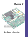
Chapter 2: Hardware information
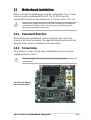
2.1 Motherboard installation ..................................................... 2-1
2.1.1 Placement direction ............................................... 2-1
2.1.2 Screw holes ........................................................... 2-1
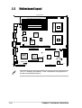
2.2 Motherboard layout ............................................................ 2-2
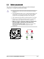
2.3 Before you proceed ............................................................ 2-3
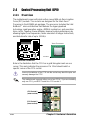
2.4 Central Processing Unit (CPU)........................................... 2-4
2.4.1 Overview ................................................................ 2-4
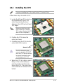
2.4.2 Installing the CPU .................................................. 2-5
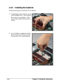
2.4.3 Installing the heatsink ............................................ 2-6
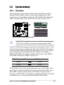
2.5 System memory ................................................................. 2-7
2.5.1 Overview ................................................................ 2-7
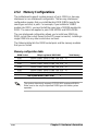
2.5.2 Memory configurations .......................................... 2-8
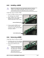
2.5.3 Installing a DIMM ................................................... 2-9
2.5.4 Removing a DIMM ................................................. 2-9

iv
Safeguards
Contents
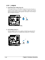
2.6 Expansion slots ................................................................ 2-10
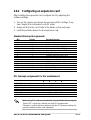
2.6.1 Installing an expansion card ................................ 2-10
2.6.2 Configuring an expansion card .............................2-11
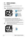
2.7 Switches and jumpers ...................................................... 2-12
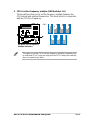
2.7.1 Switches .............................................................. 2-12
2.7.2 Jumpers ............................................................... 2-14
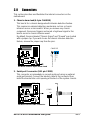
2.8 Connectors ....................................................................... 2-15
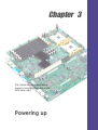
Chapter 3: Powering up
3.1 Starting up for the first time ................................................ 3-1
3.2 Powering off the computer ................................................. 3-2
Chapter 4: BIOS setup
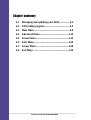
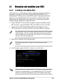
4.1 Managing and updating your BIOS .................................... 4-1
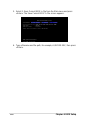
4.1.1 Creating a bootable disk ........................................ 4-1
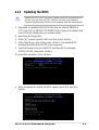
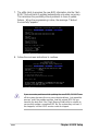
4.1.2 Updating the BIOS ................................................. 4-3
4.2 BIOS Setup program .......................................................... 4-5
4.2.1 BIOS menu bar ...................................................... 4-6
4.2.2 Legend bar............................................................. 4-6
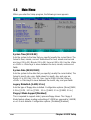
4.3 Main Menu.......................................................................... 4-8
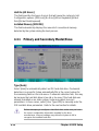
4.3.1 Primary and Secondary Master/Slave ................. 4-10
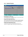
4.3.2 Keyboard Features .............................................. 4-14
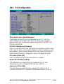
4.4 Advanced Menu ............................................................... 4-15
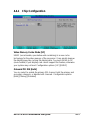
4.4.1 Chip Configuration ............................................... 4-17
4.4.2 I/O Device Configuration...................................... 4-18
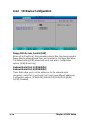
4.4.3 PCI Configuration ................................................ 4-19
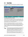
4.5 Power Menu ..................................................................... 4-21
4.5.1 Power Up Control ................................................ 4-23
4.5.2 Hardware Monitor ................................................ 4-24
4.6 Boot Menu ........................................................................ 4-26
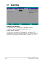
4.7 Server Menu..................................................................... 4-28
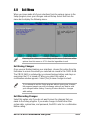
4.8 Exit Menu ......................................................................... 4-29

v
Contents
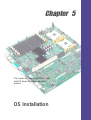
Chapter 5: OS Installation
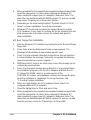
5.1 Microsoft
®
Windows
®
NT Server 4.0................................... 5-1
5.1.1 LSI
®
SCSI Driver Installation.................................. 5-1
5.1.2 Intel
®
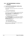
82551QM/82544GC LAN Driver Installation. 5-4
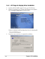
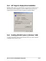
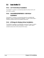
5.1.3 ATI
®
Rage XL Display Driver Installation................ 5-8
5.2 Microsoft
®
Windows
®
2000 Server ..................................... 5-9
5.2.1 LSI
®
SCSI Driver Installation.................................. 5-9
5.2.2 Intel
®
82551QM/82544GC LAN Driver Installation5-12
5.2.3 ATI
®
Rage XL Display Driver Installation.............. 5-15
5.2.4 Enabling ATA100 Feature in Windows 2000........ 5-15
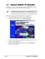
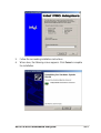
5.3 Microsoft
®
Windows
®
XP Professional.............................. 5-16
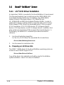
5.4 Novell
®
NetWare
®
Server.................................................. 5-18
5.4.1 LSI
®
SCSI Driver Installation................................ 5-18
5.4.2 Intel
®
82551QM/82544GC LAN Driver Installation5-20
5.4.3 ATI
®
Rage XL Display Driver Installation.............. 5-21
5.5 Linux RedHat 7.2.............................................................. 5-22
5.5.1 LSI
®
SCSI Driver Installation................................ 5-22
5.5.2 Intel
®
82551QM/82544GC LAN Driver Installation5-22
5.5.3 ATI
®
Rage XL Display Driver Installation.............. 5-22

vi
FCC/CDC statements
Federal Communications Commission Statement
This device complies with FCC Rules Part 15. Operation is subject to the
following two conditions:
• This device may not cause harmful interference, and
• This device must accept any interference received including interference
that may cause undesired operation.
This equipment has been tested and found to comply with the limits for a
Class B digital device, pursuant to Part 15 of the FCC Rules. These limits
are designed to provide reasonable protection against harmful interference
in a residential installation. This equipment generates, uses and can radiate
radio frequency energy and, if not installed and used in accordance with
manufacturer’s instructions, may cause harmful interference to radio
communications. However, there is no guarantee that interference will not
occur in a particular installation. If this equipment does cause harmful
interference to radio or television reception, which can be determined by
turning the equipment off and on, the user is encouraged to try to correct the
interference by one or more of the following measures:
• Reorient or relocate the receiving antenna.
• Increase the separation between the equipment and receiver.
• Connect the equipment to an outlet on a circuit different from that to
which the receiver is connected.
• Consult the dealer or an experienced radio/TV technician for help.
Canadian Department of Communications Statement
This digital apparatus does not exceed the Class B limits for radio noise
emissions from digital apparatus set out in the Radio Interference
Regulations of the Canadian Department of Communications.
This class B digital apparatus complies with Canadian ICES-003.
The use of shielded cables for connection of the monitor to the
graphics card is required to assure compliance with FCC regulations.
Changes or modifications to this unit not expressly approved by the
party responsible for compliance could void the user’s authority to
operate this equipment.

vii
Safety information
Electrical safety
• To prevent electrical shock hazard, disconnect the power cable from
the electrical outlet before relocating the system.
• When adding or removing devices to or from the system, ensure that
the power cables for the devices are unplugged before the signal
cables are connected. If possible, disconnect all power cables from the
existing system before you add a device.
• Before connecting or removing signal cables from the motherboard,
ensure that all power cables are unplugged.
• Seek professional assistance before using an adpater or extension
cord. These devices could interrupt the grounding circuit.
• Make sure that your power supply is set to the correct voltage in your
area. If you are not sure about the voltage of the electrical outlet you
are using, contact your local power company.
• If the power supply is broken, do not try to fix it by yourself. Contact a
qualified service technician or your retailer.
Operation safety
• Before installing the product and adding devices on it, carefully read all
the documentation that came with the package.
• Before using the product, make sure all cables are correctly connected
and the power cables are not damaged. If you detect any damage,
contact your dealer immediately.
• To avoid short circuits, keep paper clips, screws, and staples away from
connectors, slots, sockets and circuitry.
• Avoid dust, humidity, and temperature extremes. Do not place the
product in any area where it may become wet.
• Place the product on a stable surface.
• If you encounter technical problems with the product, contact a
qualified service technician or your retailer.

viii
About this guide
This user guide contains detailed information on the ASUS PR-DLSR
motherboard.
How this guide is organized
This manual contains the following parts:
• Chapter 1: Product introduction
This chapter describes the features of the PR-DLSR motherboard. It
includes brief descriptions of the special attributes of the motherboard
and the new technology it supports.
• Chapter 2: Hardware information
This chapter lists the hardware setup procedures that you have to
perform when installing system components. It includes description of
the switches, jumpers, and connectors on the motherboard.
• Chapter 3: Powering up
This chapter describes the power up sequence and gives information
on the BIOS beep codes.
• Chapter 4: BIOS setup
This chapter tells how to change system settings through the BIOS
Setup menus. Detailed descriptions of the BIOS parameters are also
provided.
• Chapter 5: OS Installation
This chapter tells how to install SCSI, LAN, and VGA drivers for
various operating systems.

ix
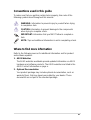
Conventions used in this guide
To make sure that you perform certain tasks properly, take note of the
following symbols used throughout this manual.
Where to find more information
Refer to the following sources for additional information and for product
and software updates.
1. ASUS Websites
The ASUS websites worldwide provide updated information on ASUS
hardware and software products. The ASUS websites are listed in the
ASUS Contact Information on page x.
2. Optional Documentation
Your product package may include optional documentation, such as
warranty flyers, that may have been added by your dealer. These
documents are not part of the standard package.
WARNING: Information to prevent injury to yourself when trying
to complete a task.
CAUTION: Information to prevent damage to the components
when trying to complete a task.
IMPORTANT: Information that you MUST follow to complete a
task.
NOTE: Tips and additional information to aid in completing a task.

x
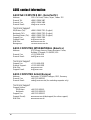
ASUS contact information
ASUSTeK COMPUTER INC. (Asia-Pacific)
Address: 150 Li-Te Road, Peitou, Taipei, Taiwan 112
General Tel: +886-2-2894-3447
General Fax: +886-2-2894-3449
General Email: [email protected]
Technical Support
MB/Others (Tel): +886-2-2890-7121 (English)
Notebook (Tel): +886-2-2890-7122 (English)
Desktop/Server (Tel): +886-2-2890-7123 (English)
Support Fax: +886-2-2890-7698
Support Email: [email protected]
Web Site: www.asus.com.tw
Newsgroup: cscnews.asus.com.tw
ASUS COMPUTER INTERNATIONAL (America)
Address: 6737 Mowry Avenue, Mowry Business Center,
Building 2, Newark, CA 94560, USA
General Fax: +1-510-608-4555
General Email: [email protected]
Technical Support
Support Fax: +1-510-608-4555
General Support: +1-502-995-0883
Web Site: www.asus.com
Support Email: [email protected]
ASUS COMPUTER GmbH (Europe)
Address: Harkortstr. 25, 40880 Ratingen, BRD, Germany
General Fax: +49-2102-442066
General Email: [email protected] (for marketing requests only)
Technical Support
Support Hotline:
MB/Others: +49-2102-9599-0
Notebook: +49-2102-9599-10
Support Fax: +49-2102-9599-11
Support (Email): www.asuscom.de/de/support (for online support)
Web Site: www.asuscom.de

xi
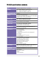
PR-DLSR specifications summary
CPU
Chipsets
Front Side Bus (FSB)
Memory
Onboard LAN
Onboard SCSI
Onboard VGA
Expansion slot
Rear panel I/O
Internal connectors
BIOS features
Form Factor
Support CD contents
Support for dual Intel
®
Xeon™ processors
RCC Grand Champion LE Server 2.0 (GCLE)
RCC Champion South Bridge 5.0 (CSB5)
RCC Champion I/O Bridge 2.0 (CIOB-X2)
400 MHz
6 x 184-pin DDR DIMM sockets
Supports 2.5V PC2100/PC1600 registered ECC DDR DIMMs
Supports 64MB to 12GB system memory
Intel
®
82544GC Gigabit Ethernet controller
Intel
®
82551QM Fast Ethernet controller
LSI
®
53C1010R PCI SCSI controller
ATI
®
RAGE-XL PCI-based VGA controller
Supports 1280 x 1024 resolution, true color
Supports 8MB PC-100 video memory
One proprietary expansion slot that supports two PCI-X
cards on a riser card module
1 x PS/2 mouse port
1 x PS/2 keyboard port
3 x RJ-45 ports
(one RJ-45 port reserved for server management)
1 x Serial port
1 x VGA port
1 x very high density SCSI connector
2 x USB 1.1 ports
1 x 68-pin Ultra-160 SCSI connectors
1 x Serial Port 2 (COM2) connector
CPU/Power/System fan connectors
24-pin, 8-pin ATX power connectors
IDE LED/Power LED connectors
SCSI connectors
Chassis intrusion connector
4Mb Flash ROM, Award BIOS with ACPI, DMI, Green, PnP
features, and Enhanced Server BIOS features
Extended ATX form factor: 12 in x 12 in (30.5 cm x 30.5 cm)
Device drivers
Management software
Utilities
Contact information

xii

ASUS PR-DLSR motherboard user guide
1-1
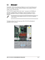
1.1 Welcome!
The ASUS
®
PR-DLSR motherboard delivers a host of new features and
latest technologies making it another standout in the long line of ASUS
quality server motherboards!
The PR-DLSR supports dual Intel
®
Xeon™ processors in 603/604-pin
package coupled with the ServerWorks
®
Grand Champion Low End
(GCLE) SystemSet to deliver a reliable and high performance server
platform.
The PR-DLSR is pre-installed in the ASUS AP1600R 1U barebone
server system.
The figure below shows the top view of the PR-DLSR motherboard
installed in the 1U system.

1-2
Chapter 1: Product introduction
1.2 Special features
1.2.1 Product highlights
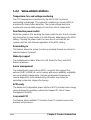
Latest processor technology
The PR-DLSR motherboard supports dual Intel
®
Xeon™ processors via
604-pin surface mount ZIF sockets. The processor features the Intel
®
NetBurst™ micro-architecture that includes hyper-pipelined technology, a
rapid execution engine, a 400MHz system bus, and an execution trace cache
to offer a significant increase in performance. See page 2-4 for more
information.
DDR memory support
Employing the Double Data Rate (DDR) memory technology, the
PR-DLSR motherboard supports up to 12GB of system memory using
PC2100/1600 registered ECC DDR DIMMs. The ultra-fast 200MHz
memory bus doubles the speed of the PC100 SDRAM to deliver the
required bandwidth for the latest Internet applications. See page 2-7.
Dual-channel Ultra-160 SCSI
The LSI
®
53C1010R 64-bit/66MHz PCI SCSI controller is onboard to
support dual-channel Ultra-160 SCSI connectors that provide high-speed
data transfer interfaces.
Advanced 64-bit PCI-X slots
The 64-bit/133MHz expansion slot onboard supports a proprietary riser
card with two PCI-X slots (on both sides). The PCI-X slots maximize I/O
bandwidth for the next generation 64-bit PCI-X cards that support
133/100MHz bus. The PCI-X specification 1.0a allows full peer-to-peer
transactions between PCI buses and provides options for intelligent I/O
and server management cards.
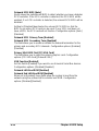
Onboard LAN
The motherboard comes with the Intel
®
82551QM Fast Ethernet controller
and the Intel
®
82544GC Gigabit Ethernet controller to support the latest
LAN technologies.

ASUS PR-DLSR motherboard user guide
1-3
Onboard VGA
The ATI Rage-XL PCI-based VGA controller integrates an 8MB display
SDRAM to provide onboard video solution.
Integrated IDE bridge
The motherboard includes two connectors to support an IDE board with
dual-channel bus master IDE connectors. The IDE connectors support
Ultra DMA 66/33, PIO modes 3 & 4 devices.

1-4
Chapter 1: Product introduction
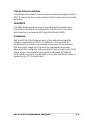
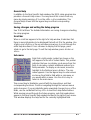
1.2.2 Value-added solutions
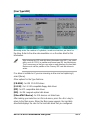
Temperature, fan, and voltage monitoring
The CPU temperature is monitored by the ASUS ASIC to prevent
overheating and damage. The system fan rotations per minute (RPM) is
monitored for timely failure detection. The system voltage levels are
monitored to ensure stable supply of current for critical components.
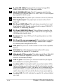
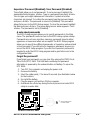
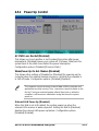
Dual function power switch
While the system is ON, pressing the power switch for less than 4 seconds
puts the system to sleep mode or to soft-off mode, depending on the BIOS
setting. Pressing the power switch for more than 4 seconds lets the
system enter the soft-off mode regardless of the BIOS setting.
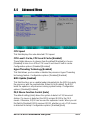
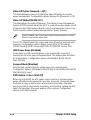
Remote Ring In
This feature allows the system to wake up remotely through an internal or
external modem, if present.
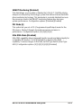
Wake-Up support
The motherboard includes Wake-On-LAN, Wake-On-Ring, and BIOS
Wake-Up features.
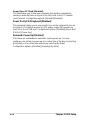
Server management
The motherboard comes with an ASMC connector that supports the
optional ASMC-HE/ME/LE card to comply with server reliability, availability,
and serviceability requirements. Remote management response via
remote diagnostics and troubleshooting still works even when the
operating system has stopped functioning.
ACPI ready
The Advanced Configuration power Interface (ACPI) provides more energy
saving features for operating systems that support OS Direct Power
Management (OSPM).
Concurrent PCI
This feature allows multiple PCI transfers from PCI master buses to the
memory and processor.

ASUS PR-DLSR motherboard user guide
1-5
Chassis intrusion detection
The motherboard supports chassis intrusion monitoring through the ASUS
ASIC. A chassis intrusion event is retained in the system memory for more
protection.
Smart BIOS
The 4Mbit firmware gives an easy-to-use interface that provides more
control and protection to the motherboard. The BIOS has a boot block
write protection and supports BIOS Boot Specification (BBS).
Compliance
Both the BIOS and the hardware levels of the motherboard meet the
stringent requirements for SDG 2.0 certification. The new SDG 2.0
requirements for systems and components are based on the following
high-level goals: support for Plug-and-Play compatibility and power
management for configuring and managing all system components, 32-bit
device drivers, and installation procedures for Windows NT/2000/XP.
Color-coded connectors and descriptive icons make identification easy as
required by the PC ‘99 specification.

1-6
Chapter 1: Product introduction
1.3 Motherboard overview
Before you install the PR-DLSR motherboard, familiarize yourself with its
physical configuration and available features to facilitate the motherboard
installation and future upgrades. A sufficient knowledge of the motherboard
specifications will also help you avoid mistakes that may damage the
board and its components.
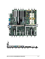
1.3.1 Major components
The following are the major components of the PR-DLSR motherboard as
pointed out in the picture on page 1-7.
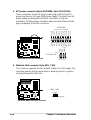
1. Intel
®
82551QM Fast Ethernet
controller
2. Intel
®
82544GC Gigabit Ethernet
controller
3. DDR DIMM sockets
4. ServerWorks
®
64-bit I/O Bridge
(CIOB-X2)
5. ServerWorks
®
Grand Champion
LE North Bridge (CMIC-LE)
6. 5-switch DIP (SW1)
7. 24-pin ATX power connector
8. 604-pin CPU sockets
9. 8-pin 12V SSI power connector
10. PCI extended power connector
11. Server management
daughterboard connectors
12. Backplane bridge board
connectors
13. ServerWorks
®
Champion South
Bridge (CSB5)
14. LPC super I/O controller
15. ASUS ASIC
16. ATI Rage-XL VGA controller
17. Zero-channel RAID connectors
18. LSI
®
SCSI controller
19. Ultra-160 SCSI connector
(internal)
20. 8-switch DIP (SW2)
21. 64-bit 133/100MHz PCI slot
22. PS/2 mouse port
23. PS/2 keyboard port
24. RJ-45 port (100/10 Mbps)
25. RJ-45 port (1000/100/10 Mbps)
26. Serial port
27. RJ-45 port (for server
management)
28. VGA port
29. SCSI LED
30. High-density SCSI connector
31. USB 1.1 ports
32. Location switch
33. Location LED
See page 1-8 for the specifications of each component. Refer to
Chapter 2 for detailed information on the components.

ASUS PR-DLSR motherboard user guide
1-7
22
23
24 25 26 27 28 29 30 31 32 33
31 5 8 9
1315
20
21
42
19
6
12
7
1618 14
11
10
17

1-8
Chapter 1: Product introduction
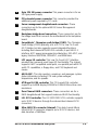
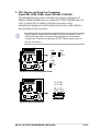
Intel
®
82551QM Fast Ethernet controller. This LAN controller fully
supports 10BASE-T/100BASE-TX networking protocols.
Intel
®
82544GC Gigabit Ethernet controller. This controller is an
integrated Ethernet LAN component that supports 1000Mbps,
100Mbps, and 10Mbps data rates. The 82544GC is optimized for
LAN on Motherboard designs (LOM), enterprise networking, and
Internet appliances that use PCI or PCI-X bus. The controller
provides a 32/64-bit, 33/66MHz interface to the PCI bus that
supports PCI Specification Rev. 2.2, and to the PCI-X extension to
the PCI Local Bus Rev 1.0a at clock rates of up to 133MHz.
DDR DIMM sockets. These six 184-pin DIMM sockets support up
to 12GB system memory using registered ECC PC2100/1600 DDR
DIMMs.
ServerWorks
®
64-bit I/O Bridge (CIOB-X2). The Champion I/O
Bridge (CIOB-X2) provides a high performance data flow path
between the IMB and the I/O subsystem, which supports multiple
PCI/PCI-X interfaces that allows large, efficient, and flexible I/O
configurations. The CIOB-X2 supports 64-bit PCI/PCI-X I/O buses
that comply with PCI 2.2 specification.
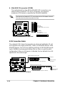
ServerWorks
®
Grand Champion LE north bridge (CMIC-LE).
The Champion Memory and I/O Controller LE (CMIC-LE) acts as
the host bridge of the Grand Champion Low End (GCLE)
SystemSet. The CMIC-LE device interfaces directly to the
processor bus, and integrates the functions of the main memory
controller and the Inter Module Bus (IMB) interface unit. The
processor interface supports a 400MHz Front Side Bus (FSB)
providing a 3.2GB/s bandwidth, 2-way interleaved 3.2GB/s memory
bandwidth with up to 12GB registered PC2100/1600 DDR DIMMs,
and two high speed IMBs plus one thin IMB to connect to the south
bridge CSB5.
5-switch DIP (SW1). This 5-switch Dual Inline Package (DIP)
allows you to set the CPU external frequency.
24-pin ATX power connector. This power connector is for an ATX
power supply.
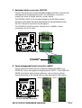
604-pin CPU sockets. Two 604-pin surface mount, Zero Insertion
Force (ZIF) sockets for the Intel
®
Xeon™ processors with a 400
MHz system bus that allows up to 3.2GB/s data transfer rate.
8
7
6
5
4
3
2
1
1.3.2 Core specifications
Page is loading ...
Page is loading ...
Page is loading ...
Page is loading ...
Page is loading ...
Page is loading ...
Page is loading ...
Page is loading ...
Page is loading ...
Page is loading ...
Page is loading ...
Page is loading ...
Page is loading ...
Page is loading ...
Page is loading ...
Page is loading ...
Page is loading ...
Page is loading ...
Page is loading ...
Page is loading ...
Page is loading ...
Page is loading ...
Page is loading ...
Page is loading ...
Page is loading ...
Page is loading ...
Page is loading ...
Page is loading ...
Page is loading ...
Page is loading ...
Page is loading ...
Page is loading ...
Page is loading ...
Page is loading ...
Page is loading ...
Page is loading ...
Page is loading ...
Page is loading ...
Page is loading ...
Page is loading ...
Page is loading ...
Page is loading ...
Page is loading ...
Page is loading ...
Page is loading ...
Page is loading ...
Page is loading ...
Page is loading ...
Page is loading ...
Page is loading ...
Page is loading ...
Page is loading ...
Page is loading ...
Page is loading ...
Page is loading ...
Page is loading ...
Page is loading ...
Page is loading ...
Page is loading ...
Page is loading ...
Page is loading ...
Page is loading ...
Page is loading ...
Page is loading ...
Page is loading ...
Page is loading ...
Page is loading ...
Page is loading ...
Page is loading ...
Page is loading ...
Page is loading ...
Page is loading ...
Page is loading ...
Page is loading ...
Page is loading ...
Page is loading ...
Page is loading ...
Page is loading ...
Page is loading ...
Page is loading ...
Page is loading ...
Page is loading ...
Page is loading ...
Page is loading ...
Page is loading ...
Page is loading ...
-
 1
1
-
 2
2
-
 3
3
-
 4
4
-
 5
5
-
 6
6
-
 7
7
-
 8
8
-
 9
9
-
 10
10
-
 11
11
-
 12
12
-
 13
13
-
 14
14
-
 15
15
-
 16
16
-
 17
17
-
 18
18
-
 19
19
-
 20
20
-
 21
21
-
 22
22
-
 23
23
-
 24
24
-
 25
25
-
 26
26
-
 27
27
-
 28
28
-
 29
29
-
 30
30
-
 31
31
-
 32
32
-
 33
33
-
 34
34
-
 35
35
-
 36
36
-
 37
37
-
 38
38
-
 39
39
-
 40
40
-
 41
41
-
 42
42
-
 43
43
-
 44
44
-
 45
45
-
 46
46
-
 47
47
-
 48
48
-
 49
49
-
 50
50
-
 51
51
-
 52
52
-
 53
53
-
 54
54
-
 55
55
-
 56
56
-
 57
57
-
 58
58
-
 59
59
-
 60
60
-
 61
61
-
 62
62
-
 63
63
-
 64
64
-
 65
65
-
 66
66
-
 67
67
-
 68
68
-
 69
69
-
 70
70
-
 71
71
-
 72
72
-
 73
73
-
 74
74
-
 75
75
-
 76
76
-
 77
77
-
 78
78
-
 79
79
-
 80
80
-
 81
81
-
 82
82
-
 83
83
-
 84
84
-
 85
85
-
 86
86
-
 87
87
-
 88
88
-
 89
89
-
 90
90
-
 91
91
-
 92
92
-
 93
93
-
 94
94
-
 95
95
-
 96
96
-
 97
97
-
 98
98
-
 99
99
-
 100
100
-
 101
101
-
 102
102
-
 103
103
-
 104
104
-
 105
105
-
 106
106


Ask a question and I''ll find the answer in the document
Finding information in a document is now easier with AI
Related papers
Other documents
-
Gigabyte Superb 550P User manual
-
Broadcom LSI53C1020 Ultra320 SCSI User guide
-
-
SPARKLE GEFORCE 210 SXG210256D2L-NM - PCI User manual
-
LSI SEN S11005 - Requirements for Synchronous Negotiation When Using the SYM53C140 in System User manual
-
-
-
Abocom UFE1500 User manual
-
-