Page is loading ...

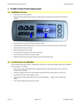
APOLLO 120 /150 III
12.1”/15.1” TFT Intel
®
Celeron/Pentium
®
III
Plastic-housing Panel PC with
Versatile
Stand design
User’s Manual (Version 2207)

Copyright Notice
This document is copyrighted 2002 by the Manufacturer.
The information provided in this document has been
carefully checked and is accurate at the time of publication.
However, the Manufacturer assumes no responsibility for
any infringements of patents or other rights of third parties
that may result from its use.
No part of this publication may be reproduced, stored in a
retrieval system, or transmitted in any form of or via any
means without the prior written permission of the
Manufacturer. Further, this publication and features
described herein are subject to change without notice.
Trademarks
All brand and product names used for identification in this
document are trademarks or registered trademarks of their
respective companies.
© Copyright 2002, July. Version 2207
All rights reserved.
Printed in Taiwan

Unpacking
After unpacking the APOLLO 120/150 III carton, check
and see if the following items are included and in good
condition.
u APOLLO III main system x 1
u Accessories
- Power cord (90
o
) x 1
- External FDD cable (optional) x 1
- External 5V/12V DC power cable (optional) x 1
- Utilities & drivers & user manual CD diskette x 1
(for touchscreen drivers, please download the
updated drivers from the following website
http://www.3m.com or
http://www.elotouch.com
- Base knob with rubber cushion x 1
- Panel mounting kit (optional) x 1 set
Make sure that all of the items listed above are present. If
any of the above items is missing, contact your dealer
immediately.
Warranty
All products manufactured by the Manufacturer. are
warranted against defective materials and workmanship for
one year starting from the date of delivery to the original
purchaser. However, warranty or service will not be
extended if 1). the product is repaired, modified or altered
unless such repair, modification or alteration is authorized
by the Manufacturer; or 2). the product serial number or
warranty label is defaced or missing; or 3). the product is
not properly used.

Important Safety Precautions
Before getting started, read these instructions and save
them for later reference.
1. Turn off the computer before cleaning. Clean with a
damp or dry cloth only. Do not spray any liquid cleaner
on screen directly.
2. The power outlet socket used to plug in the computer
power cord must be located near the system and easily
accessible. Do not use outlets on the same circuit of
the systems that regularly switched on and off.
3. Make sure the voltage of the power source is correct
before connecting the computer to the power outlet.
4. If the computer is sharing an extension cord with other
devices, make sure the total ampere rating of the
devices plugged into the extension cord does not
exceed the cord’ s ampere rating.
5. Do not expose the power cord, extension cord and
power outlet to moisture.
6. Install the computer on a reliable surface to prevent
damage caused by dropping.
7. This computer is not equipped with an operating
system. An operating system must be loaded first
before installing any software into the computer.
8. Disconnect the power cord from the computer before
any installation. Make sure both the computer and the
external devices are turned off. The sudden surge of
power may ruin any sensitive components. Also make
sure the computer is properly grounded.
9. During installation of any internal components, be sure
to ground yourself to keep from any static charge.
Most electronic components are sensitive to the static
electric charge. Use a grounding wrist strap and place
all electronic components in any static-shielded
devices.

10. The openings on the computer enclosure are for the
cabin ventilation to prevent the computer from
overheating. DO NOT COVER THE OPENINGS.
11. The brightness of the flat panel display will decrease
with use. However, hours of use will vary depending on
the application environment.
12. If the computer is equipped with a touch panel, avoid
using sharp objects to operate the touch panel.
Scratches on the touch panel may cause
mal-calibration or non-function to the panel.
13. The LCD panel display is not subject to shock or
vibration. When assembling the computer, make sure
it is securely installed.

Table of Contents
1. INTRODUCTION............................................. 1-1
1.1. GENERAL INFORMATION ..................................1-2
1.2. WHAT COVERS IN THIS MANUAL.........................1-3
1.3. SPECIFICATIONS...........................................1-5
1.4. DIMENSIONS .............................................1-10
1.4.1. APOLLO 120 ........................................1-10
1.4.2. APOLLO 150 ........................................1-11
2. USING THE SYSTEM..................................... 2-13
2.1. IDENTIFYING THE SYSTEM..............................2-14
2.1.1. Front View...........................................2-14
2.1.2. Side Views...........................................2-15
2.1.3. I/O Outlets..........................................2-16
2.2. SYSTEM SETUP FOR THE FIRST-TIME USE............2-17
2.2.1. Installation Procedures..........................2-17
2.2.2. Running the BIOS Setup .......................2-18
2.2.3. Operating System and Driver Installation 2-19
3. VERSATILE STANDING & MOUNT OPTIONS .3-21
3.1. VERSATILE STAND .......................................3-22
3.1.1. Standing Upright..................................3-22
3.1.2. 45 to 90
0
Free Standing ........................3-22
3.1.3. Fixed Standing.....................................3-23
3.1.4. Cable Management...............................3-24
3.2. WALL MOUNTING AND MOBILE APPLICATIONS.......3-25
3.3. PANEL MOUNTING .......................................3-27
3.4. KIOSK INTEGRATION ..................................3-28
4. I/O CONNECTION........................................ 4-29
4.1. PARALLEL PORT ..........................................4-30
4.2. COM PORTS X 4 ........................................4-31
4.3. 100/10 BASE-T ETHERNET (RJ-45)................4-33
4.4. VGA INTERFACE.........................................4-33
4.5. 2
ND
DISPLAY GRAPHIC SUPPORT MODE...............4-34

4.5.1. When System Memory Clock = 66MHz....4-34
4.5.1.1. Single Display Mode........................4-35
4.5.1.2. Mirror Display Output Mode..............4-36
4.5.1.3. Multiple Display Output Mode ...........4-37
4.5.2. When System Memory Clock = 100MHz ..4-38
4.5.2.1. Single Display Mode........................4-38
4.5.2.2. Mirror Display Output Mode..............4-39
4.5.2.3. Multiple Display Output Mode ...........4-40
4.5.3. When System Memory Clock = 133MHz ..4-41
4.5.3.1. Single Display Mode........................4-42
4.5.3.2. Mirror Display Output Mode..............4-43
4.5.3.3. Multiple Display Output Mode ...........4-44
4.6. PS/2 KEYBOARD INTERFACE...........................4-45
4.7. PS/2 MOUSE INTERFACE...............................4-45
4.8. EXTERNAL FDD (DB-15) .............................4-46
4.9. +5V/12V DC-OUT ....................................4-47
4.10. VR BRIGHTNESS CONTROL ............................4-47
4.11. DIO (DIGITAL INPUT & OUTPUT) ....................4-48
4.12. AUDIO INTERFACE (LINE-IN, MIC-IN, SPK-OUT) .4-50
4.13. USB PORTS..............................................4-50
4.14. IR KEYBOARD SENSOR (OPTIONAL) ..................4-50
4.15. AC/DC INLET/POWER SWITCH .......................4-50
5. HARDWARE INSTALLATION AND UPGRADE.5-51
5.1. RECOGNIZING THE SYSTEM MAJOR PARTS ...........5-53
5.2. INSTALLING THE CPU...................................5-55
5.3. INSTALLING THE SDRAM MEMORY MODULE ........5-56
5.4. MOTHERBOARD ASSEMBLY .............................5-57
5.5. TOUCH CONTROLLER ASSEMBLY .......................5-58
5.6. HDD MODULE ASSEMBLY ..............................5-59
5.7. TOUCHSCREEN OR FRONT BEZEL ASSEMBLY .........5-60
5.8. LCD MODULE ASSEMBLY...............................5-62
5.9. CD-ROM/DVD-ROM/FDD MODULE ASSEMBLY ..5-66
5.9.1. Internal CD-ROM/FDD Assembly ............5-66
5.9.2. External FDD Connection.......................5-68
5.10. POWER MODULE ASSEMBLY ............................5-69
5.11. EXPANSION OUTLETS & RISER CARD ASSEMBLY....5-71
5.12. BACK PANEL ASSEMBLY.................................5-72
5.13. STAND MODULE ASSEMBLY.............................5-73

6. SYSTEM MOTHERBOARD & I/O BOARD........ 6-75
6.1. APOLLO III MOTHERBOARD..........................6-76
6.1.1. General Information .............................6-76
6.1.2. Specifications.......................................6-77
6.1.3. Locating Jumpers & Connectors..............6-79
6.1.4. Jumpers & Jumper Setting.....................6-80
6.1.4.1. DOC 2000 Address Setting (JP1).......6-81
6.1.4.2. Clear CMOS (JP2) ...........................6-81
6.1.4.3. 232/485 Setting (JP5,6,7,8,9 & 10) ..6-81
6.1.5. Connectors & Pin Assignment.................6-82
6.1.5.1. PWR3: ATX Power connector ............6-83
6.1.5.2. J2: CD Audio IN.............................6-84
6.1.5.3. J7: HDD LED & ACPI LED & SMI........6-84
6.1.5.4. J8: IR / CIR Connector ....................6-84
6.1.5.5. J9: Power LED & KB ........................6-85
6.1.5.6. SW1: ATX Power ON/OFF & Reset .....6-85
6.1.5.7. COM3............................................6-85
6.1.5.8. LCD1: LCD Connector......................6-86
6.1.5.9. INV1: LCD Inverter Connector.........6-87
6.1.5.10. FDD1: FDD connector.....................6-87
6.1.5.11. IDE1/IDE2: Primary/Secondary HDD.6-88
6.1.5.12. SCSI 1: PRT Port/Serial Port/DIO Port6-89
6.1.5.13. SCSI 2: KB/MS/VGA/LAN USB/FDD...6-90
6.1.5.14. CN4: PCI/ISA Expansion Slot............6-91
6.2. APOLLO III I/O BOARD ..............................6-94
6.2.1. Locating Jumpers & Connectors..............6-94
6.2.2. Jumpers & Jumper Setting.....................6-95
6.2.2.1. JP1: Keyboard Power Select ............6-95
6.2.2.2. COM port Power Selection................6-95
6.2.3. Connectors & Pin Assignment.................6-96
6.2.3.1. KB1: PS/2 Keyboard Connector ........6-97
6.2.3.2. KBMS: PS/2 Mouse .........................6-97
6.2.3.3. COM1, COM2, COM4: DB-9 .............6-97
6.2.3.4. CN1: DC Power Output...................6-98
6.2.3.5. LPT1: D-SUB-25 Parallel Port............6-98
6.2.3.6. CRT1: VGA (D-SUB 15 Pin) ..............6-98
6.2.3.7. FDD1: External FDD Connector.......6-99
6.2.3.8. J11: USB 1 , USB2 Connector.........6-99

6.2.3.9. DIO1: RJ-11 Connector ...................6-99
6.2.3.10. LAN1: RJ-45 Ethernet Connector ......6-99
6.2.3.11. MIC1...........................................6-100
6.2.3.12. LINE 1......................................... 6-100
6.2.3.13. SPK 1.......................................... 6-100
6.2.3.14. SCSI 1: PRT/Serial Port/DIO Port....6-101
6.2.3.15. SCSI 2: KB/MS/VGA/LAN USB/FDD.6-102
7. AWARD BIOS SETUP.................................. 7-103
7.1. AWARD BIOS..........................................7-104
7.2. CONTROL KEY DEFINITION........................... 7-105
7.3. GETTING HELP .........................................7-106
7.3.1. Main Menu.........................................7-106
7.4. AWARD BIOS SETUP ............................... 7-106
7.4.1. AWARD BIOS Setup Main Menu............7-106
7.4.2. Standard CMOS Features.....................7-108
7.4.3. Advanced BIOS Features.....................7-111
7.4.4. Advanced Chipset Features.................. 7-115
7.4.5. Integrated Peripherals ........................7-121
7.4.6. Power Management Setup...................7-125
7.4.7. PnP/PCI Configuration.........................7-129
7.4.8. PC Health Status ................................7-131
7.4.9. Frequency Voltage Control...................7-132
7.4.10. Load Fail-Safe Defaults .......................7-134
7.4.11. Load Optimized Defaults......................7-135
7.4.12. User Password ...................................7-136
7.4.13. Save and Exit Setup ...........................7-137
7.4.14. Exit Without Saving............................7-138
8. SOFTWARE & DRIVERS INSTALLATION ..... 8-139
8.1. ETHERNET DRIVERS...................................8-140
8.2. PC 610 AGP XGA...................................8-141
8.3. AUDIO SETUP ..........................................8-142
8.4. DRIVER INSTALLATION................................8-143

9. TOUCHSCREEN........................................... 9-145
9.1. MICROTOUCH TOUCH DRIVER INSTALLATION......9-146
9.1.1. Two types of MicroTouch touchscreens.. 9-146
9.1.2. TouchWare–the MicroTouch Software.... 9-147
9.1.3. Installing TouchWare ..........................9-149
9.1.4. Uninstalling TouchWare.......................9-151
9.1.5. Calibrate the MicroTouch Touchscreen ..9-152
9.1.6. Getting More Information ....................9-153
9.2. ELO TOUCHSCREEN DRIVER INSTALLATION ........9-154
9.2.1. System Requirements.........................9-154
9.2.2. About Elo Software.............................9-155
9.2.3. Installation........................................9-156
9.2.4. Installing MonitorMouse for Win 95.......9-161
9.2.5. Installing MonitorMouse for Win NT.......9-165
9.2.6. Getting More Information ....................9-167
APPENDIX .....................................................9-168
A: LCD SPECIFICATION.........................................9-168
B: DISKONCHIP INSTALLATION.............................. 9-171
C: WAKE-ON-LAN ..............................................9-173
D: FIRST MB MEMORY MAP....................................9-176
E: POWER SUPPLY................................................9-177

User Manual version 2007
APOLLO 120/150 III
1-1
1. INTRODUCTION
This chapter provides background
information and detail specification on
the APOLLO 120/150 III. Sections in this
chapter include:
u General Information
u What covers in this Manual
u Specification
u Dimension

User Manual version 2207
APOLLO 120/150 III
1-2
1.1. General Information
The information revolution which started from the mid ’90
inaugurated a new competitive era where consumer-
computing technology was exploited to business operation
quicker than ever before. Many enterprises from our life
related industries such as POS, POI, KIOSK, Banking,
Medical to the high-tech Telecom, Aerospace,
Semiconductor … etc. all are eager or forced to automate
their industries with PCs in order to thrive in this new age. For
their industrial automation, there is one thing in common, i.e.
space is always a premium and system stability is always a
must in their environmental applications.
The APOLLO 120/150 is a 12.1"/15.1" TFT Intel
Celeron/Pentium III/Pentium IV plastic-housing multimedia
panel PC system. With a 150W ATX power supply as its
engine, the APOLLO is a genuine P4 panel PC designed for
high performance multimedia application. Featuring with
versatile stand design for different environmental
applications, the APOLLO itself can be used as a
ready-to-play system by connecting to necessary peripherals.
By integrating the APOLLO system to the special designed
HERCULUS KIOSK, the complete system is widely used for
KIOSK integration. It also provides 2 sets of VESA holes for
market-available swing arms for mobile application. Also with
the availability of both AC and DC systems, the APOLLO is the
best turnkey solution platform for any system integration.
In terms of panel size, the APOLLO has 12.1” and 15.1”
systems. In terms of system engine, the APOLLO also have
two versions, one APOLLO III, Celeron/Pentium III system
and the other APOLLO IV, Pentium IV system. To upgrade
the system, simply replace the motherboard.
Fully configurable and with its sleek outlook, the APOLLO is
an ideal platform for any space-constricted application.

User Manual version 2007
APOLLO 120/150 III
1-3
1.2. What Covers in this Manual
This handbook contains most information you need to set up
and use the APOLLO III system. You do not need to read
everything in this handbook to use the system.
For a quick start, see the following chapter summaries;
Chapter 1 (the current chapter) provides background
information and detail specification on the
APOLLO 120/150 III.
Chapter 2 identifies the APOLLO III system exterior
components and provides instructions to help
you to use the system as soon as possible.
Chapter 3 details the panel PC’s various standing and
mounting options by graphical illustrations.
Chapter 4 provides the procedures to connect external
devices to the I/O interface
Chapter 5 helps you to recognize the APOLLO system
internal components. It also provides the
installation procedures including LCD,
touchscreen, power supply module, CPU, system
memory, FDD, HDD and CD-ROM drive.
Chapter 6 provides detail information of the jumper settings
and connector signals of the system control
board.
Chapter 7 explains the AWARD BIOS setup.
Chapter 8 introduces the Ethernet, XGA and audio drivers.
Chapter 9 details the procedures to install the touchscreen
software drivers under DOS and Windows
operation

User Manual version 2207
APOLLO 120/150 III
1-4
Appendix A details the 12.1”/15.1” LCD specifications.
Appendix B introduces the DiskOnChip installation.
Appendix C introduces the Wake-On-LAN feature.
Appendix D explains the first MB memory map.
Appendix E provides the specifications for the built-in power
supply.

User Manual version 2007
APOLLO 120/150 III
1-5
1.3. Specifications
APOLLO: 12.1”/15.1” TFT Intel
®
Celeron/Pentium
®
III &
Pentium IV Plastic-housing Panel PC with
Versatile Stand design
SYSTEM
Flat Panel
u APOLLO 120: 12.1” color TFT, 800*600
Viewing angle 100
Luminance (cd/m
2
) 150 or above
Simultaneous mode yes
u APOLLO 150: 15.1” color TFT, 1024*768
Viewing angle 120
Luminance (cd/m
2
) 200 or above, optional
high-luminance model
Simultaneous mode yes
CPU (Socket 370)
u Intel Pentium III FCPGA 1GHz/133MHz
u Intel Pentium III FCPGA 650-933/133MHz
u Intel Pentium III FCPGA 500E-850E/100MHz
u Intel Celeron FCPGA 800MHz-1.10GHz/100MHz
u Intel Celeron FCPGA 533AMHz-766MHz/66MHz
u Intel Celeron PPGA 300A-533MHz/66MHz
System Chipset
u SiS 630ST
System BIOS
u Award PnP Flash BIOS
System Memory
u 1*168pin DIMM socket supporting SDRAM up to 512MB
L2 Cache
u CPU built-in

User Manual version 2207
APOLLO 120/150 III
1-6
Standard I/O
- Serial ports*4: COM 1, 2 & 4 with +5V/12 power
output on pin #9, COM 3 internal type reserved for
touchscreen, COM2 RS-232/485 jumper selectable
- Parallel Port*1: supports SPP/EPP/ECP
- External FDD Interface*1
- +5V/+12V DC-out*1
- PS/2 Keyboard Interface*1
- PS/2 Mouse Interface*1
- DIO: Input*2, output*2
- USB Interface*2
- VGA Interface*1
- Brightness VR*1
- Speaker-out, MIC-in, Line in
Ethernet
u 100/10 Base-T Ethernet with RJ-45 phone jack
u Supports WAKE-ON-LAN
Watchdog Timer
Display
u Integrated 2D/3D graphics engine, 4X AGP
u Share system memory architecture able to utilize the
display memory size up to 64MB
u Supporting LCD/VGA dual display mode (under
Windows 98 and Windows ME and Windows XP)

User Manual version 2007
APOLLO 120/150 III
1-7
Audio Function
u Full duplex and independent sample rate converter for
audio recording & playback
u Supports Microsoft DirectSound
u 3D positional audio effects
u Hi-performance, mixed-signal, stereo
u MIC-In, Speaker-Out, Line-In
u Pin header for CD-audio in
Hardware Monitor
u Monitoring processor & system
u Monitoring 5VSB, VBAT, 1.5V, 3.3V, +5V, +12V, -12V, and
processor voltages
u Monitoring processor, chassis fan speeds
u Controlling processor and chassis fan speed and failure
alarm
u Automatic fan on/off control
u Read back capability that displays temperature, voltage
and fan speed
u Supporting Intel processor thermal diode output (real
processor temperature)
Expansion Slot
- PCI*2 or PCI*1 + ISA*1
- Expansion card size (L*W)
- PCI card: max. 190*120 mm
- ISA card max. 190*120 mm if no internal FDD is
installed; 170*120 mm if internal FDD is installed
Front Bezel
- LED indicators for HDD, LAN, POWER
- Motion sensor or IrDA receiver or Wireless keyboard
receiver (optional)

User Manual version 2207
APOLLO 120/150 III
1-8
PERIPHERAL & STORATE DEVICES
Touchscreen (optional, sharing COM3)
u 12.1”/15.1” analog resistive type with RS-232 controller
u 12.1”/15.1” capacitive type with RS-232 controller
u 12.1”/15.1” surface acoustic wave type (SAW)
Power Supply
u ATX 150W, input range: 100~240V/5A @60Hz,
200~240V/2.5A @50Hz
u DC 150W, 20~28VDC, 40~56VDC or DC 200W, 36~72VDC
(optional)
Speakers
u Water-proof speakers*2
CD-ROM or CD-RW or DVD-ROM
u Slim type*1 (optional) or
u External type via USB
Floppy Disk Drive
u Slim type*1 (optional) or
u Via external FDD or
u External type via USB
Hard Disk Drive
u 3.5" HDD*1 (optional)

User Manual version 2007
APOLLO 120/150 III
1-9
MECHANICAL & ENVIRONMENTAL
Construction
u Inside: heavy-duty steel
u Outside: fire-proof resilient ABS/PC plastic
Color (standard)
u Beige
u Black
Dimension (chassis only, unit: mm)
u APOLLO 120: 368*321*116.5 (L*W*D);
334.7*284.21 (for panel mount)
u APOLLO 150: 406*360*129 (L*W*D);
384*284.2 (for panel mount)
Mounting
u Panel mount with mounting kits
u Wall mount with swing arm: standard VESA mounting
holes (75*75 mm)
Versatile Stand
u 45~90
o
free standing
u Avocado-shape holes for fixed standing
u Cable Management design
§ Specifications are subject to change without notice.

User Manual version 2207
APOLLO 120/150 III
1-
10
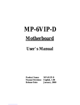
1.4. Dimensions
1.4.1. APOLLO 120
The APOLLO 120’s chassis size is shown below. This does not
include the dimension of the stand. This does not include the
dimension of the stand.
Figure 1-1: APOLLO 120 DIMENSION
/