Page is loading ...

User Manual
Classroom Audio System
860
CAT 860

TABLE OF CONTENTS
SECTION 1: 6 Important Safety Instructions
Overview 8 System Components and Unpacking
10 Optional Components
11 CAT 860 Front Panel Controls
12
CAT 860 Rear Panel Controls
13 Infrared Sensor / Receiver (ISR) Connections
14 REDMIKE Controls and Connections
15 Cradle Charger Controls and Connections
SECTION 2: 16 Step 1. Location of the Amplifier
Set-up & Use 17 Step 2. IR Sensor / Receiver (ISR) Installation
20 Step 3. Installation of Amplifier Wall-Mount Bracket
20 Step 4. Speaker Installation
21 Step 5A. Connect the Power Supply
21 Step 5B. ISR Connection
22 Step 5C. Speaker Connection(s)
22 Step 5D. Audio Input Connections
23 Step 6. Audio Integration
24 Step 7. Charging the REDMIKE
25 Step 8. Set-up and Operation of REDMIKE
26 9. Audio Equalization of the CAT 860
27 10. Output to Personal Assistive Listening Device
28 11. Using the REDMIKE to Amplify External Audio
Equipment
29 12. PageFirst: Priority Mute
30 13. RS-232 Serial Interface Programming
30 Serial Interface Protocol
30 RS-232 Data Signals
31 Connector Signal Wiring
31 Command Structure
32 Summary of Command & Response
Transactions
34 Control Character Hex Value and Definition
34 General Format for Action Command Exchange
for Basic and Advanced Command Set:
35 General Format for Query Command
Exchange:
35 General Format for Aborted Command
Exchange (Both Basic and Advanced Command
Sets:

36 14. RS-232 Serial Interface Command Definition
Basic Command Set for Audio Switcher
Operations
Audio Input Functions for the A/V Source
Group
36 1. Enable Audio/Video Source Command
37 2. Increment Audio/Video Sources
Command
38 3. Decrement Audio/Video Sources
Command
39 4. Increment Microphone Audio Inputs
Command
40 5. Mute Audio/Video Sources Command
41 6. Un-mute Enabled Audio/Video Source
Command
42
7. Mute Microphone Audio Inputs Command
42
8. Un-mute Microphone Audio Inputs Command
43
9. Toggle Mute for Enabled Audio/Video Source
Command
44
10. Toggle Mute for Microphone Audio Inputs
Command
45
11. Query Enabled Audio/Video Source
Command
46
12. Query Absolute Volume Audio/Video Source
Command
47
13. Query Absolute Volume Microphone Audio
Input Command
48
14. Query Mute for Audio/Video Source
Command
49
15. Query Mute for Microphone Audio Inputs
Command
Advanced Command Set for Audio Mixer
Operations
Audio Input Functions for the A/V Source Group
50
1. Select Audio Input Command
51
2. Query Selected Audio Input Command
Audio Input Functions for the A/V Source Group
52
1. Differentially Increase Volume for Selected
Audio Input Command
53
2. Differentially Decrease Volume for Selected
Audio Input Command
54
3. Set Absolute Volume for Selected Audio Input
Command
55
4. Query Absolute Volume for Selected Audio
Input Command
56
5. Select Audio Output Command
54
6. Differentially Increase Volume for Selected
Audio Output Command
Audio Input Functions for the Infrared Source
Group
56
1. Select Infrared Input Command
57
2. Differentially Increase Volume for Selected
Infrared Input Command
58
3. Differentially decrease volume for selected
infrared input Command
59
4. Set Absolute Volume for Selected Infrared
Input Command
60
5. Query Absolute Volume for Selected Infrared
Input Command
Input Muting Functions Group
66
1. Mute Selected Audio Input Command
67
2. Un-Mute Selected Audio Input Command
System Management Functions Group
68
1. Query Model and Software Version Command
67
2. Un-Mute Selected Audio Input Command
System Management Functions Group
68
1. Query Model and Software Version Command
SECTION 3: 71 REDMIKE VC: Controls and Connections
Optional Accessories 72 Charging
72 Initial Set-Up
73 LT-71: Controls and Connections
74 Charging
75 Initial Set-Up
76 REDMIKE Share: Controls and Connections
77 Charging
78 Initial Set-Up
79 iR Media Connector: Initial Setup
80 Audio Integration
80 Other Optional Accessories
SECTION 4: 81 Troubleshooting Guide
Troubleshooting 82 Tips to Obtain Optimal Audio Performance
SECTION 5: 83 Warranty Statement
Warranty &
Specifications
85 Safety Warnings and Certifications
86 System Specifications
TABLE OF CONTENTS CONT’DTABLE OF CONTENTS CONT’D
55
7. Differentially Decrease Volume for Selected
Audio Output Command
56
8. Set Absolute Volume for Selected Audio
Output Command
57
9. Query Absolute Volume for Selected Audio
Output Command

1. Read these instructions.
2. Keep these instructions.
3. Heed all warnings.
4. Follow all instructions.
5. Do not use the apparatus near
water.
6. Clean only with dry cloth.
7. Do not block any ventilation
openings. Install in accordance
with the manufacturer’s
instructions.
8. Do not install near any heat
sources such as radiators,
heat registers, stoves, or other
apparatus (including amplifiers)
that produce heat.
9. Do not defeat the safety purpose
of the polarized or grounding-type
plug. A polarized plug has two
blades with one wider than the
other. A grounding- type plug has
two blades and a third grounding
prong. The wide blade or the third
prong is provided for your safety. If
the provided plug does not fit into
your outlet, consult an electrician
for replacement of the obsolete
outlet.
10. Protect the power cord from
being walked on or pinched
particularly at plugs, convenience
receptacles, and the point where
they exit from the apparatus.
11. Only use attachments/ accessories
specified by the manufacturer.
12. Use only with a cart, stand, tripod,
bracket or table specified by the
manufacturer, or sold with the
apparatus. When a cart is used,
use caution when moving the cart/
apparatus combination to avoid
injury from tip-over.
13. Unplug this apparatus during
lighting storms or when unused for
long periods of time.
14. Refer all servicing to qualified
service personnel. Servicing is
required when the apparatus has
been damaged in any way, such
as power-supply cord or plug is
damaged, liquid has been spilled
or objects have fallen into the
apparatus, the apparatus has been
exposed to rain or moisture, does
not operate normally, or has been
dropped.
15. When the mains plug or appliance
coupler used as the disconnect
device, it shall remain readily
operable.
16. Please keep the unit in a good
ventilation environment.
IMPORTANT SAFETY INSTRUCTIONS
6

8 9
1. Overview
3. Optional
Accessories
4. Troubleshooting
5. Warranty, Safety
& Specifications
1. Overview 2. Setup & Use
3. Optional
Accessories
4. Troubleshooting
5. Warranty, Safety
& Specifications
2. Setup & Use
Speakers and Speaker Wire
Systems can be configured with a variety of different speaker types,
including the following:
Standard Components
AMP-860 Audio amplifier/mixer
PS-24V-2.5 24V/2.5A power supply for CAT 860
RX-ISR Infrared sensor/receiver with mounting bracket
CA-PSE50 50’ plenum-rated Cat 5e cable
RMT REDMIKE classroom microphone with battery
BA-NH2A27 AA NiMH rechargeable sensing battery for REDMIKE
AC-RMLC2 REDMIKE lavaliere cord
BC-RMCC REDMIKE cradle charger
PS-5V-1.0 5V/1.0A power supply for cradle charger
SPEAKERS Contact Lightspeed at 800.732.8999 for speaker info
NXQ (x 1)
WMQ (x 4)
DRQ (x 4)
MCQ (x 1)
Amplifier Power
Supply
SECTION 1:
OVERVIEW
SYSTEM COMPONENTS AND UNPACKING
The standard configuration of the CAT 860 will contain:
ISR Infrared Sensor/
Receiver and Cable
Charging Cradle and
Power Supply
REDMIKE®
Classroom
Microphone
CAT 860 Amplifier
860

10 11
1. Overview
3. Optional
Accessories
4. Troubleshooting
5. Warranty, Safety
& Specifications
1. Overview 2. Setup & Use
3. Optional
Accessories
4. Troubleshooting
5. Warranty, Safety
& Specifications
2. Setup & Use
860
FRONT PANEL CONTROLS
1. POWER SWITCH/INDICATOR:
Press this button to turn the CAT
860 ON (pushed in) or OFF. When
the POWER is switched on, the
blue LED indicator will light.
2. AUDIO INDICATORS: These
lights flash red when audio (voice)
from the microphone is detected.
3. A VOLUME: Controls the volume
of the teacher microphone (set to
channel A).
4. B VOLUME: Controls the volume
of the student or second teacher
microphone (set to channel B).
5. AUDIO INPUT VOLUMES:
Control the volume of the audio
coming from the media source
(computer, TV/VCR, CD/DVD, etc.)
connected to the corresponding
input on the rear panel.
6. ALD OUTPUT AND VOLUME:
This jack sends mixed audio to
external equipment such as an
assistive listening device (Personal
FM System) or recording device.
Use the volume control to set
the optimum signal level for the
device.
2
2
1
3
4
5
6
OPTIONAL COMPONENTS
Optional equipment which may be part of your CAT 860 system:
REDMIKE® VC
Volume Control
Microphone
REDMIKE Share
Handheld Mic &
Charger Cable
LT- 71
LT-71 LightMic
and Charger
Cable
Optional Components
RMV REDMIKE VC microphone with battery
RMS REDMIKE Share handheld microphone with battery pack
LT71 LightMic microphone with batteries
BA-NH2A27 AA NiMH rechargeable sensing battery for REDMIKE
BA-NH2APK NiMH rechargeable battery pack for REDMIKE Share
BA-NH1 AA NiMH rechargeable battery for LT71 (2 per microphone)

12 13
1. Overview
3. Optional
Accessories
4. Troubleshooting
5. Warranty, Safety
& Specifications
1. Overview 2. Setup & Use
3. Optional
Accessories
4. Troubleshooting
5. Warranty, Safety
& Specifications
2. Setup & Use
INFRARED SENSOR/RECEIVER (ISR)
CONNECTIONS
1. POWER INDICATOR: This light
will glow blue when the ISR is
receiving power from the CAT 860.
2. A/B IR INDICATORS: These lights
glow when the corresponding
microphone (set to channel A or
B) is turned on and transmitting.
A steady light indicates a strong
signal.
3. SENSOR OUT: Connect the CAT 5
sensor cable to this connection to
send audio from the microphones
to the CAT 860 amplifier.
4. IR EXPANSION: Connect up to
three passive IR sensors (IR-SR70F)
to this connection for larger
classrooms. For more than one
additional sensor a 3-way coax
splitter is required (HS3).
1
2
3
4
RS-232 IN
Front Panel RS-232
Control Select
12
++--
RS-232 IN
Front Panel RS-232
Control Select
12
++--
1. CONTROL SELECT: Both
microphone and aux input volume
can be adjusted from the front
panel controls or remotely from
a controller via the RS-232 Serial
Interface. This switch selects either
front panel control or RS-232
control. Front panel controls are
ignored during RS-232 operation.
2. RS-232 IN: A 9 pin connector
to connect the CAT 860 to an
external controller.
3. SPEAKER OUTPUTS (1–4): These
binding post connectors are used
to connect the CAT 860 to the
speakers. Depending on speaker,
all outputs may not be used.
*Note: Wiring to these terminals
should follow the Class 2 wiring
methods as outlined in the
National Electric Code.
4. CHARGERS: These jacks can
be used to charge the optional
LightMic or handheld mic as an
alternative to connecting them to
the REDMIKE cradle charger.
5. DC POWER: Plug the 24 V power
supply into this jack.
6. PAGING INPUT AND ADJ:
Connect the input from optional
PageFirst sensor here when
interface with a buildings paging
system. Use the ADJ control to
adjust the sensitivity if needed.
7. EQUALIZER (4-BAND): Adjust
these controls upon installation to
properly equalize the system to
produce optimium audio quality
from the microphone(s).
8. AUX OUT AND VOL: This jack
sends audio to external equipment
such as an assistive listening
device (Personal FM System) or
recording device. Use the volume
control to set the optimum signal
level for the device.
9. AUDIO INPUTS: These
connections accept an audio
signal from other technology so
all multimedia can be distributed
evenly throughout the classroom.
10. SENSOR INPUT: The infrared
microphone audio from the ISR is
connected to this input via CAT 5
cable. Connect additional sensors
to the CAT 860 to cover large or
odd-shaped classrooms.
11. SENSOR SHORT: This LED glows
red when there is a short in the
ISR or cable. The system will not
operate, but is protected from
damage when the LED is lighted.
REAR PANEL CONTROLS
1
2
3
4
10
11
7
8
9
5
4

14 15
1. Overview
3. Optional
Accessories
4. Troubleshooting
5. Warranty, Safety
& Specifications
1. Overview 2. Setup & Use
3. Optional
Accessories
4. Troubleshooting
5. Warranty, Safety
& Specifications
2. Setup & Use
1. CHARGE INDICATORS: The light
glows RED while the REDMIKE is
charging. When fully charged, the
light will glow GREEN. A blinking
RED light indicates that no battery
is sensed, (REDMIKE Yellow
Protective Tab may not have been
completely removed—see page
10, item 4.) A blinking Green LED
means a non- Lightspeed battery
has been installed (possibly an
alkaline battery).
2. DC POWER PORT: Connect the
DC power cord here.
3. OPTIONAL CHARGING PORT:
Plug the charging cord for the
optional LT-71 or the REDMIKE
Share microphones here.
CRADLE CHARGER CONTROLS AND
CONNECTIONS
1
2
3
1. POWER BUTTON: Press this
button to turn the REDMIKE ON,
press again to turn it OFF (mute).
2. POWER/LOW BATTERY
INDICATOR: A BLUE light
indicates the REDMIKE is on and
fully charged. A RED light indicates
a charge is needed.
3. BATTERY COMPARTMENT: To
access the battery compartment,
slide the door downward. The
battery should only be replaced
by a Lightspeed AA rechargeable
sensing battery (part # BA-
NH2A27).
4. YELLOW PROTECTIVE TAB:
Slide the battery compartment
door open to remove this
disposable protective tab before
use. NOTE: do not attempt to
remove the tab without first
opening the compartment door, as
it may tear, leaving fragments.
5. AUDIO/MICROPHONE INPUT:
Use this input to plug in a laptop,
MP3 player or other audio
source to wirelessly transmit
audio to be played through the
system. Alternatively, an external
microphone can be connected.
6. CHANNEL SELECT SWITCH
(CH A/B): This switch allows
for selection between Channel
A or B. If you are using a single
microphone, we recommend using
Channel A.
7. CHARGER CONTACTS (+ -):
These contacts interface with the
charging tabs in the BC-RMCC
cradle charger for daily charging.
Simply place the REDMIKE in the
charger.
REDMIKE CONTROLS AND CONNECTIONS
1
2
3
5
6
7
S
l
i
d
e
b
a
t
t
e
r
y
d
o
o
r
o
p
e
n
R
e
m
o
v
e
t
a
b
b
e
f
o
r
e
u
s
e
4

16 17
1. Overview 2. Setup & Use
3. Optional
Accessories
4. Troubleshooting
5. Warranty, Safety
& Specifications
1. Overview 2. Setup & Use
3. Optional
Accessories
4. Troubleshooting
5. Warranty, Safety
& Specifications
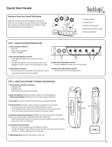
2. IR SENSOR/RECEIVER (ISR) INSTALLATION
Next, find a suitable location for the ISR. Poor location will cause substandard
performance of the CAT 860 Classroom Audio System. The ISR should be as
high as possible in the room – the ceiling is the best location, centered along the
longest wall in the room. When possible, use a conduit to protect the wires (not
included). Poor choices for placement are corners, on walls at heights lower than
7 feet (2 meters), or in places where the line of sight from the ISR to the receiver
is or could be obstructed.
Good placement
Conduit is Recommended
Best placement
Avoid!
First, find a suitable location to set-up the amplifier. It is best to put the amplifier
in a stable location near the other equipment to be used. It can be set in a
cabinet, on a tabletop, or mounted on the wall with the included bracket.
Media Cabinet Set-up
The included wall bracket is
specifically designed to support the
CAT 860.
Wall-mount Set-up
SECTION 2:
SET-UP & USE
1. LOCATION OF THE AMPLIFIER
Avoid Separated Set-ups
Components should be housed
together. Wires should be routed
back directly to the amplifier.

18 19
1. Overview 2. Setup & Use
3. Optional
Accessories
4. Troubleshooting
5. Warranty, Safety
& Specifications
1. Overview 2. Setup & Use
3. Optional
Accessories
4. Troubleshooting
5. Warranty, Safety
& Specifications
1. Screw the bracket to a place high
on the wall or in the middle of the
solid ceiling. Mount the bracket
horizontally as shown above.
2. Uncoil the Cat 5 sensor cable.
Connect one end of the cable to
the ISR. Route the wire back to
the CAT 860 amplifier, securing
it along with way using surface
raceway where possible.
3. Slide the ISR onto the bracket until
it “clicks” into place.
2. IR SENSOR/RECEIVER (ISR) INSTALLATION
CONT’D
Wall/Solid Ceiling Mount
a. Guide the mounting rails onto
the bracket, oriented as
pictured.
b. Once secure, the ISR locks
into place.
c. To remove the ISR, slide a ruler
or screwdriver behind the ISR to
press the release bar down and
slide the ISR off the bracket
4. Connect the other end of the Cat
5 sensor cable into the SENSOR
INPUT jack on the CAT 860
amplifier.
2. IR SENSOR/RECEIVER (ISR) INSTALLATION
CONT’D
Once you find a suitable location for the ISR, follow these instructions to mount
it. There are different instructions for mounting depending on if the ISR will be
mounted to a suspended ceiling grid or secured to a wall / solid vertical surface.
1. Attach the bracket to the ceiling
tile grid (t-bar).
a. Slide the tabs onto the outsides
of the t-bar, starting with one
corner.
b. Attach the second tab around
the other side of the t-bar.
c. Repeat with the other side of
the bracket so it is connected at
all four points.
2. Slide the ISR onto the bracket until
it “clicks” into place.
a. Guide the mounting rails onto
the bracket, oriented as
pictured.
b. Once secure, the ISR locks into
place.
c. To remove the ISR, press the
release bar down and slide the
ISR off the bracket.
3. Uncoil the Cat 5 sensor cable.
Connect one end of the cable to
the ISR. Secure wire overhead and
route it back to the system.
4. Connect the other end of the Cat
5 sensor cable into the SENSOR
INPUT jack on the CAT 860
amplifier.
Suspended Ceiling Mount
clip connects to t-bar on ceiling
Release Bar

20 21
1. Overview 2. Setup & Use
3. Optional
Accessories
4. Troubleshooting
5. Warranty, Safety
& Specifications
1. Overview 2. Setup & Use
3. Optional
Accessories
4. Troubleshooting
5. Warranty, Safety
& Specifications
5B. ISR CONNECTION
5A. CONNECT THE POWER SUPPLY
1. Ensure the power is still switched
off.
2. Check the connection from the ISR
to the CAT 860. Ensure the sensor
cable is securely attached and
locked into place.
1. Ensure the power button is
depressed in the OFF position.
2. Connect the CD end of the power
supply to the black power jack
labeled DC POWER.
3. Connect the black AC power cable
from the power supply to a wall
outlet.
RS-232 IN
Front Panel RS-232
Control Select
12
++--
CAT 860 Amplifier
DC Power Source Cable
ISR Sensor/Receiver
CAT 860 Amplifier
The CAT 860 systems include a bracket for optional wall-mounting.
4. SPEAKER INSTALLATION
3. INSTALLATION OF AMPLIFIER WALL-
MOUNT BRACKET
1. Locate the speaker installation
instructions packed with your
speaker(s).
2. Follow instructions and mount
speaker(s).
3. Return to this manual to complete
the set up of your system.
A. Determine the location:
a. It should be located near a
power outlet.
b. Height should allow for access to
front control panel, but also be
in compliance with building and
ADA regulations.
B. Screw the bracket to the wall at
the two screw hole points with
the included hardware. Attach
to a stud when possible; use the
drywall mollies when studs are not
available.
C. Slide the CAT 860 onto the bracket
using the channel on the bottom
of the amplifier.
D. Secure the CAT 860 to the bracket
by tightening the screw on the
bottom.
E. Now that the CAT 860 is secure,
it can be slowly pulled out and
pivoted for better access to the
back panel. Push the CAT 860 back
in, to lock into place.
F. The power supply can be set
on the back of the bracket and
secured with ties if desired.

22 23
1. Overview 2. Setup & Use
3. Optional
Accessories
4. Troubleshooting
5. Warranty, Safety
& Specifications
1. Overview 2. Setup & Use
3. Optional
Accessories
4. Troubleshooting
5. Warranty, Safety
& Specifications
6. AUDIO INTEGRATION
The next step in setting up your CAT 860 system is to connect it to the other
multimedia devices in your classroom. You may have a computer, television,
DVD/VCR player, a visual projection system or other devices. Below are
instructions on how to integrate TV/VCR, CD/DVD or computer directly into the
CAT 860.
1
7
3
4
5
6
2
1. PROJECTOR
2. LAPTOP
3. CAT 860
4. DVD
5. ISR SENSOR
6. TEACHER’S MICROPHONE
7. SPEAKERS
1. Ensure the power is switched
off and the audio input volume
controls are turned all the way
down.
2. Connect the appropriate RCA or
3.5mm audio cable (not included)
from the audio source into the
corresponding input jack on the
rear panel of the CAT 860.
3. With both the CAT 860 and the
audio source power on, adjust the
corresponding volume control on
the CAT 860 until the desired level
is achieved.
One Possible Set-up
RS-232 IN
Front Panel RS-232
Control Select
12
++--
RS-232 IN
Front Panel RS-232
Control Select
12
++--
5C. SPEAKER CONNECTION(S)
5D. AUDIO INPUT CONNECTIONS
Next, connect the CAT 860 to the speakers. Then, be sure any auxiliary audio
sources are connected to the corresponding labeled input on the CAT 860.
1. Ensure speaker wire connections
are secure and not frayed.
*Note: Wiring to these terminals
should follow the Class 2 wiring
methods as outlined in the
National Electric Code.

24 25
1. Overview 2. Setup & Use
3. Optional
Accessories
4. Troubleshooting
5. Warranty, Safety
& Specifications
1. Overview 2. Setup & Use
3. Optional
Accessories
4. Troubleshooting
5. Warranty, Safety
& Specifications
8. SETUP AND OPERATION OF REDMIKE
Once the REDMIKE is charged, follow these steps to set it up for use.
1. Turn the CAT 860 power on. The
blue LED will glow.
2. Remove the REDMIKE from the
charging cradle and turn it on.
3. Slip the REDMIKE with lanyard
around the neck and position the
top of the microphone just below
the collarbone. NOTE: Positioning
of the REDMIKE is critical for
proper volume adjustment.
4. While speaking in a normal voice
slowly increase the volume of the
corresponding channel on the
CAT 860 until your voice is barely
audible. Each REDMIKE has its
channel pre-set to either A or B, as
indicated on the back of the Mic.
REMEMBER: This equipment
supplements the user’s voice
so they are able to speak in a
conversational tone. Having the
volume set too high will result in
feedback and listener fatigue.
5. Once initial volume level is set,
walk around the room and listen
for audio dropout and overall
audio quality. Fine-tuning the
audio is accomplished by making
minor adjustments to the 4-Band
Equalizer on the back panel of the
CAT 860.
6. If a second REDMIKE was
purchased, repeat steps 2-4.
7. CHARGING THE REDMIKE
Before use, the REDMIKE should be charged. It will take 8-9 hours for the
REDMIKE to obtain a full charge. A fully charged REDMIKE will last for over 7
hours of use. If microphones are used daily, they should be kept in the cradle –
microphones can be left in a charging cradle constantly for up to 2 weeks without
causing degradation to battery life.
A red light on the charging cradle indicates the REDMIKE is charging. A green
light indicates that charging is complete and a full charge has been reached. A
blinking light indicates a charging or sensing error. See Troubleshooting section
for more information.
REDMIKE incorporates alkaline protection into the microphone design. Always
use a Lightspeed rechargeable sensing battery. Replacement AA NiMH batteries
may only be purchased through Lightspeed Technologies (part # BA-NH2A27).
Do not attempt to charge alkaline batteries. They can overheat and expand
creating a significant hazard and damaging the microphone (this is not covered
by warranty).
1. Plug power cord into the cradle
charger and then plug the AC end
into an electrical outlet.
2. Ensure that the REDMIKE is turned
OFF.
3. Place the REDMIKE into the
cradle. The LED on the cradle
will glow RED indicating charging
has started. When the REDMIKE
is fully charged the LED on the
cradle charger will change to
GREEN.

26 27
1. Overview 2. Setup & Use
3. Optional
Accessories
4. Troubleshooting
5. Warranty, Safety
& Specifications
1. Overview 2. Setup & Use
3. Optional
Accessories
4. Troubleshooting
5. Warranty, Safety
& Specifications
10. OUTPUT TO PERSONAL ASSISTIVE
LISTENING DEVICE (ALD)
1. Turn the ALD (Assistive Listening
Device) volume control on the
back panel all the way down (fully
counterclockwise).
2. Determine the size and type of
audio input jack on the device as
many manufacturers’ products
differ in connector size and shape.
The Lightspeed LES-370 Personal
FM System requires a 3.5 mm to
3.5 mm patch cable (part# CA-
MMC3535, not included).
3. Connect a patch cable from the
ALD’s microphone jack or AUX
input to one of the following
3.5mm audio jack on the CAT 860:
• “ALDOUT”onthefrontpanel
• “AUXOUT”onthebackpanel
4. Adjust the volume control on
the ALD’s receiver to maximum
output. NOTE! This is to set the
maximum allowable signal from
the CAT 860.
5. With the CAT 860 and ALD turned
on, speak into the REDMIKE and
slowly adjust the corresponding
volume control on the CAT 860
until the appropriate audio level is
obtained in the ALD.
RS-232 IN
Front Panel RS-232
Control Select
12
++--
RS-232 IN
Front Panel RS-232
Control Select
12
++--
9. AUDIO EQUALIZATION OF THE CAT 860
• Thevoiceshouldbenatural,
very clear and without any audio
feedback (ringing)
• Walktheroomlisteningforthe
overall quality and any feedback
that is present
• Ifthereisalotofaudiofeedback,
it is likely the volume is too high.
Ensure the volume is at the
appropriate level, a second person
is helpful to determine this.
• Iffeedbackisstillpresentwiththe
audio set at the right level, make
the following EQ adjustments:
– High pitched ring: lower the 2K
and/or 4K adjustment by _ turn
– Lower pitched ring: lower the
500 and/or 1K adjustment by _
turn
• Ifyounoticethesoundis“muddy”
or has too much bass:
– Lower the 500 adjustment by _
turn and/or
– Raise the 2K or 4K adjustment by
1/8 turn
• Note:theEQadjustmentsshould
be preset at “12:00.” This is the
nominal level and any adjustments
(up or down) should be made from
this level.
The CAT 860 uses a 4-band audio equalizer designed to optimize and fine-tune
the microphone sound quality for the classroom. Below are some tips on proper
system equalization:

28 29
1. Overview 2. Setup & Use
3. Optional
Accessories
4. Troubleshooting
5. Warranty, Safety
& Specifications
1. Overview 2. Setup & Use
3. Optional
Accessories
4. Troubleshooting
5. Warranty, Safety
& Specifications
12. PAGEFIRST: PRIORITY MUTE
This optional feature interfaces with an independent classroom paging system.
When the page is broadcast, all audio from the system is muted, ensuring
important school-wide messages are never missed.
How it works:
1. PageFirst sensor clip is hung
around the lead wires attached to
the classroom paging speaker.
2. The clip is hard-wired to the CAT
860.
3. As a page is broadcast, the
sensor clip detects the audio
signal through induction and
immediately mutes the CAT 860.
4. When the page is over, the audio
from the CAT 860 returns to
normal volume level.
(For full installation details refer to
the install sheet included with the
optional PageFirst sensor clip)
11. USING THE REDMIKE TO AMPLIFY
EXTERNAL AUDIO EQUIPMENT
The REDMIKE includes a 3.5mm audio input jack to connect to an audio source
like a laptop or MP3 player. The REDMIKE will transmit the audio signal to be
played through the system.
If your system includes two REDMIKEs, we recommend using Channel B (student
mike) to amplify the external audio equipment so the teacher’s volume on the
Channel A (teacher mike) does not have to be adjusted.
To determine which REDMIKE is set to Channel B, you can look at the switch on
the back of the mike or speak into one of the mics and watch which set of LED’s
glow on the front panel of the CAT 860 (A Volume or B Volume correspond to
Channels A or B).
1. Plug your external audio
equipment (for example, laptop),
into the input on the REDMIKE
labeled “INPUT” using a 3.5mm
patch cable.
2. Adjust the volume on the CAT
860 receiver which corresponds to
selected mic channel A or B.
AUDIO
OUTPUT
AUDIO
INPUT

30 31
1. Overview 2. Setup & Use
3. Optional
Accessories
4. Troubleshooting
5. Warranty, Safety
& Specifications
1. Overview 2. Setup & Use
3. Optional
Accessories
4. Troubleshooting
5. Warranty, Safety
& Specifications
13. RS-232 SERIAL INTERFACE
PROGRAMMING CONT’D
An external controller, in the form of an intelligent wall panel or a personal
computer, can use the RS-232 serial link to remotely send commands to initiate
actions or queries for the CAT 860. In response, the CAT 860 uses the RS-232
serial link to send acknowledgements or status data back to external controller.
There are two operational command sets; the Basic Command Set for
audio switching and the Advanced Command Set for audio mixing. It is not
recommended to intermix commands from the two command sets.
The Basic Command Set treats the CAT 860 as a simple audio switcher
where only one of four audio/video sources is enabled at one time. The two
microphone channels are controlled as a pair independently from the audio/
video sources. The low-cost serial controllers with their limited functionality
will typically will be restricted to a subset of the Basic Command Set. These
controllers usually cannot utilize the query commands, or the response packets.
More capable high-end serial controllers can take advantage of the complete
features of the Basic Command Set.
The Advanced Command Set treats the CAT 860 as an audio mixer which is
aligned with the traditional usage for Lightspeed CAT 800 series products. The
Advanced Command Set requires the more capable high-end serial controllers
to utilize the CAT 860 to its greatest potential.
It is expected that each button press from the serial controller would use only a
single action/query command packet. If a single button press must issue a string
of multiple action/query command packets then each packet must be separated
by at least a 10ms delay, or alternately, a new command packet must wait until
the CAT 860 issues a response packet/character before it can be sent.
Connector Signal Wiring
Command Structure
* Only 3-Pin Connection
DTE PIN ASSIGNMENTS (DB-9)
1 DCD Data Carrier Detect
2* RxD Received Data
3* TxD Transmitted Data
4 DTR Data Terminal Ready
5* GND Ground (Signal)
6 DSR Data Set Ready
7 RTS Request to Send
8 CTS Clear to Send
9 RI Ring Indicator
13. RS-232 SERIAL INTERFACE
PROGRAMMING
The CAT 860 uses standard RS-232 protocols as a serial link to an external
control module such as an intelligent wall panel, or a personal computer.
When the Control Select switch in the “RS-232” position, the serial link
offers remote access to operational control circuitry within the CAT 860 for
the purpose of controlling the volume of the audio input and output ports.
Additionally, the serial links allows remote queries of internal CAT 860 system
status.
Command and parameter characters travel serially along the RS-232 signal link
between the external controller and the CAT 860. The command and parameter
information is in the form of two hexadecimal values contained in the 8-data bits
of each RS-232 character. The above graphic illustrates a typical RS-232 logic
waveform representing a character (Data format: 1 Start bit, 8 Data bits, No
Parity, 1 Stop bit). The data transmission starts with a Start bit, followed by the
data bits (LSB sent first and MSB sent last), and ends with a “Stop” bit.
The voltage of Logic “1” (Mark) is between -3VDC to -15VDC, while the Logic “0”
(Space) is between +3VDC to +15VDC.
RS-232 Data Signals
RS-232 LOGIC WAVEFORM (8N1)
Serial Interface Protocol
CAT 860 RS-232 SETTINGS
Sync. Method: Asynchronous
Stop Bits: Accepts 1 or 2 stop bits
Baud Rate: 9600 baud
Parity: None
Data Size: 8-bits
Connector: 9-Pin, Female D-Sub

32 33
1. Overview 2. Setup & Use
3. Optional
Accessories
4. Troubleshooting
5. Warranty, Safety
& Specifications
1. Overview 2. Setup & Use
3. Optional
Accessories
4. Troubleshooting
5. Warranty, Safety
& Specifications
f. Return Absolute Audio Output Channel Volume Setting
g. Return Mute/Un-mute Status for Audio Inputs
5. Action/Query Response Functions:
a. Not Acknowledge (NACK) is the response for any aborted commands.
b. Action Command response is to repeat back the command packet sent
by the serial controller. Some action command packets do not have a
<Param> character, but all response packets will have one or two <Param>
characters.
Example: CMD><Param><Param><EOT>
Example: <STX><CMD><Param><EOT>
c. The Query Command response is for the most part the query command
repeated back to the serial controller. However, the response packet also
includes one or two imbedded <Param> characters which contain the
values of the pertinent CAT 860 registers.
Example: CMD><Param><Param><EOT>
Example:
<STX><CMD><Param><EOT><STX><CMD><Param><Param><EOT>
Example: <STX><CMD><Param><EOT>
Summary of command and response transactions Cont’d:
13. RS-232 SERIAL INTERFACE
PROGRAMMING CONT’D
1. Action Command Functions for the Basic Command Set (Audio Switcher
Operations):
a. Enable One of Four Audio/Video Sources
b. Increment and Decrement All Audio/Video Sources by 2dB
c. Increment and Decrement Both Microphone Channels by 2dB
d. Mute and Un-mute All Audio/Video Sources
e. Mute and Un-mute Both Microphone Channels
2. Query Command Functions for the Basic Command Set (Audio Switcher
Operations):
a. Return Absolute Microphone Source Volume Setting
b. Return Audio/Video Source Selection Status (TV/VCR, CD/DVD, COMP, or
AUX)
c. Return Absolute Audio/Video Source Volume Setting
d. Return Mute/Un-mute Status for Microphone Source Inputs
e. Return Mute/Un-mute Status for Audio/Video Source Inputs
3. Action Command Functions for the Advanced Command Set (Audio Mixer
Operations):
a. Select Control of Microphone Input Channel (A or B)
b. Set Differential Microphone Input Channel Volume
c. Set Absolute Microphone Input Channel Volume
d. Select Control of Audio/Video Source (TV/VCR, CD/DVD, COMP, or AUX)
e. Set Differential Audio/Video Source Volume
f. Set Absolute Audio/Video Source Volume
g. Select Control of Audio Output Channel (AUX)
h. Set Absolute Audio Output Channel Volume
i. Set Mute/Un-mute of Any or All Audio Inputs
4. Query Command Functions for the Advanced Command Set (Audio Mixer
Operations):
a. Return Microphone Input Channel Selection Status (A or B)
b. Return Absolute Infrared Input Channel Volume Setting
c. Return Audio/Video Source Selection Status (TV/VCR, CD/DVD, COMP, or
AUX)
d. Return Absolute Audio/Video Source Volume Setting
e. Return Audio Output Channel Selection Status (AUX)
Summary of command and response transactions:
13. RS-232 SERIAL INTERFACE
PROGRAMMING CONT’D

34 35
1. Overview 2. Setup & Use
3. Optional
Accessories
4. Troubleshooting
5. Warranty, Safety
& Specifications
1. Overview 2. Setup & Use
3. Optional
Accessories
4. Troubleshooting
5. Warranty, Safety
& Specifications
13. RS-232 SERIAL INTERFACE
PROGRAMMING CONT’D
General Format for Query Command Exchange:
In this example the external controller sends query command packet to CAT
860. CAT 860 repeats back the action command packet in response which also
includes one or two imbedded <Param> characters. The <Param> characters
which are added to the query command packets contain the values of the perti-
nent internal CAT 860 registers.
Controller: <STX><CMD><EOT>
CAT 860: <STX><CMD><Param><Param><EOT>
General Format for Aborted Command Exchange (Both Basic and Advanced
Command Sets:
In this example the external controller sends either an action or query command
to CAT 860 and the command is either corrupted or unsupported. The <Param>
characters can be absent.
Controller: <STX><CMD><Param><EOT>
CAT 860: <NACK>
Note: It is expected that each button press from the serial controller would use
only a single command/query packet. If a single button press must issue a string
of multiple command/query packets then each packet must be separated by at
least a 10ms delay, or alternately, a new packet must wait until the CAT 860 issues
a response packet/character before it can be sent.
Control Character Hex Value and Definition
STX (0x02) Start character of an action command packet.
EOT (0x04) End character of any command packet.
ACK (0x06) Only response character from the CAT 860
if action command (PING command only) is
properly received and accepted.
NACK (0x15) Only response character from the CAT 860 if
any command is corrupted or unsupported.
The CAT 860 should send a NACK if:
1. The CAT 860 can not recognize the start or
command characters.
2. The CAT 860 does not receive an end
character after receiving a total of twenty
characters after receiving valid start and
command characters.
3. The CAT 860 does not receive an end
character after waiting 50ms after receiving
valid start and command characters.
CMD (find hex value
from Table 1)
This is the general symbol for the command
character derived from Table 1.
Param (find hex value
from Table 1)
This is the general symbol for the parameter
character(s) associated with the command
character. They are derived form Table 1.
13. RS-232 SERIAL INTERFACE
PROGRAMMING CONT’D
General Format for Action Command Exchange for Basic and Advanced
Command Set:
In this example, the serial controller sends an action command packet to the
CAT 860 and in response the CAT 860 repeats back the action command packet
the serial controller. The <Param> characters can be absent from the action
command packet, but all response packets will have one or two added <Param>
characters containing the values of the pertinent internal CAT 860 register.
Controller: <STX><CMD><Param><EOT>
CAT 860: <STX><CMD><Param><EOT>

36 37
1. Overview 2. Setup & Use
3. Optional
Accessories
4. Troubleshooting
5. Warranty, Safety
& Specifications
1. Overview 2. Setup & Use
3. Optional
Accessories
4. Troubleshooting
5. Warranty, Safety
& Specifications
<CMD>
Symbol
Hex
Value
<Param> Value Definition
IAVS 0xE1 Command Packet:
The controller sends no
<Param> character in the
command packet.
Increment the volume of
the selected audio input
by 2 dB. This overrides any
previous mute commands.
The remaining three
unselected audio/video
source inputs remain muted.
Response Packet:
If the command is properly
received, the CAT 860
responds by repeating back
the command packet to
the serial controller with an
added imbedded <Param>
character containing the
value loaded.
If the command is not
received properly, the CAT
860 responds by sending a
<NACK> character.
14. RS-232 SERIAL INTERFACE
COMMAND DEFINITION CONT’D
BASIC COMMAND SET FOR AUDIO SWITCHER OPERATIONS CONT’D
Audio Input Functions for the A/V Source Group Cont’d
2. INCREMENT AUDIO/VIDEO SOURCES COMMAND
<CMD>
Symbol
Hex
Value
<Param> Value Definition
AVS p 0xE0 Command Packet:
The controller sends only
one <Param> character in
the command packet. The
possible values are shown
below:
0x80 = Enable TV/VCR
0x81 = Enable CD/DVD
0x82 = Enable COMPUTER
0x83 = Enable AUX IN
0x84 = Enable All Inputs **
** Power up default used
to facilitate initial system
installation.
Select (enable) one of four
Audio/Video input sources
to receive audio. The
remaining three unselected
Audio/Video input ports
will be muted by sending
the -79dB setting their
corresponding volume
control hardware registers.
Note that muting inputs
does not change the values
in any of the volume-level
EEPROM variables.
Response Packet:
If the command is properly
received, the CAT 860
responds by repeating back
the command packet to the
serial controller.
If the command is not
received properly, the CAT
860 responds by sending a
<NACK> character.
Power up default initially
has all six audio inputs
enabled. The power up
default settings for all six
input volume-level EEPROM
variables is the setting for
-40dB.
14. RS-232 SERIAL INTERFACE
COMMAND DEFINITION
BASIC COMMAND SET FOR AUDIO SWITCHER OPERATIONS
Audio Input Functions for the A/V Source Group
1. ENABLE AUDIO/VIDEO SOURCE COMMAND

38 39
1. Overview 2. Setup & Use
3. Optional
Accessories
4. Troubleshooting
5. Warranty, Safety
& Specifications
1. Overview 2. Setup & Use
3. Optional
Accessories
4. Troubleshooting
5. Warranty, Safety
& Specifications
<CMD>
Symbol
Hex
Value
<Param> Value Definition
IMAI 0xE3 Command Packet:
The controller sends no
<Param> character in the
command packet.
Increment the volume for
microphone channel A
and B audio by 2 dB. This
overrides any previous mute
commands.
Response Packet:
If the command is properly
received, the CAT 860
responds by repeating
back the command packet
with an added imbedded
<Param> character
containing the value loaded.
If the command is not
received properly, the CAT
860 responds by sending a
<NACK> character
DMAI 0xE4 Command Packet:
The controller sends no
<Param> character in the
command packet.
Decrement the volume of
the microphone channel A
and B audio by 2 dB. This
overrides any previous mute
commands.
Response Packet:
If the command is properly
received, the CAT 860
responds by repeating
back the command packet
with an added imbedded
<Param> character
containing the value loaded.
If the command is not
received properly, the CAT
860 responds by sending a
<NACK> character.
14. RS-232 SERIAL INTERFACE
COMMAND DEFINITION CONT’D
BASIC COMMAND SET FOR AUDIO SWITCHER OPERATIONS CONT’D
Audio Input Functions for the A/V Source Group Cont’d
4. INCREMENT MICROPHONE AUDIO INPUTS COMMAND
DECREMENT MICROPHONE AUDIO INPUTS COMMAND
14. RS-232 SERIAL INTERFACE
COMMAND DEFINITION CONT’D
<CMD>
Symbol
Hex
Value
<Param> Value Definition
DAVS 0xE2 Command Packet:
The controller sends no
<Param> character in the
command packet.
Decrement the volume of
the selected audio input
by 2 dB. This overrides any
previous mute commands.
The remaining three
unselected audio/video
source inputs remain muted.
Response Packet:
If the command is properly
received, the CAT 860
responds by repeating
back the command packet
with an added imbedded
<Param> character
containing the value loaded.
If the command is not
received properly, the CAT
860 responds by sending a
<NACK> character.
BASIC COMMAND SET FOR AUDIO SWITCHER OPERATIONS CONT’D
Audio Input Functions for the A/V Source Group Cont’d
3. DECREMENT AUDIO/VIDEO SOURCES COMMAND
/