MULTI-POINT
INSTALLATION INSTRUCTIONS
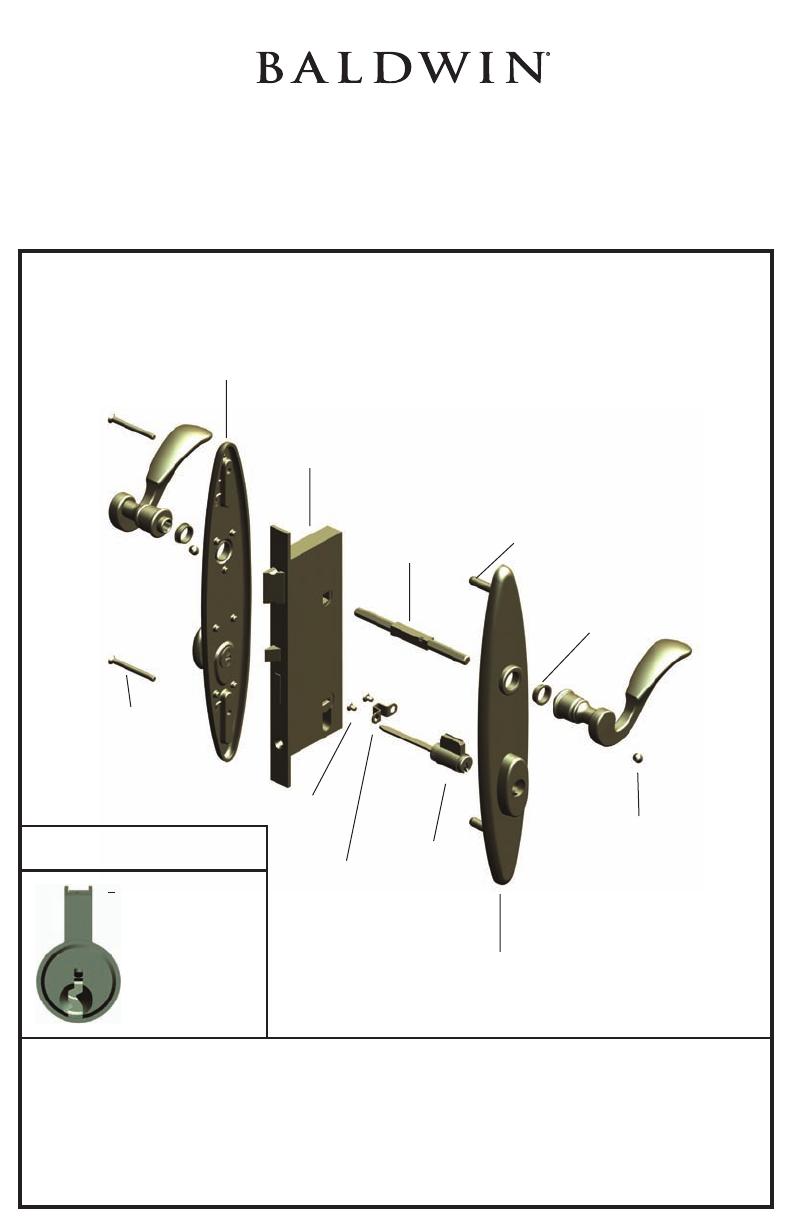
SPRINGFIELD TRIM SHOWN
SEE HARDWARE
CATALOG FOR HOLE SPACING
Entrance American Cylinder Function Exploded View
INTERIOR TRIM
LOCK BODY
SPINDLE
POSITION NOTCHES
TOWARDS DOOR
EXTERIOR
THREADED
SCREW POSTS
SEE NOTE
PRESS-IN
BUSHINGS
LEVER SET SCREWS
ALIGN WITH
SPINDLE GROOVE
EXTERIOR TRIM
LOCK
CYLINDER
CYLINDER
BRACKET
BRACKET
SCREWS
INTERIOR #8
MACHINE SCREWS
DRILL THROUGH 5/16”
SEE NOTE
Lock Cylinder Note: Shown is the lever on the top of the lock cylinder. The lever may be on
the bottom, depending on the lock.
#8 Machine Screws Note: Proper trim alignment requires installing the spindle and levers
before completely securing the #8 screws.
Threaded Screw Posts Note: Length may need to be cut down to accomodate different
door manufacturers’ hole pattern.
©2007 BALDWIN HARDWARE CORPORATION, READING, PA
CYLINDER PIN
HOUSING FACING
UP. SEE NOTE
RECOMMENDED CYLINDER
ORIENTATION
PK 5903 (10/07)


