Page is loading ...

1034, 036, 036 QS
© 2001 Andreas Stihl AG & Co., Waiblingen
Contents
1 Introduction 2
2 Safety Precautions 3
3 Specifications 4
3.1 Engine 4
3.2 Fuel System 4
3.3 Ignition System 5
3.4 Cutting Attachment 5
3.5 Tightening Torques 6
3.6 Special Accessories 7
3.6.1 For User 7
3.6.2 For Service 7
4 Clutch, Chain Drive,
Chain Brake and
Chain Tensioner 8
4.1 Clutch Drum and Chain
Sprocket 8
4.2 Replacing the
Chain Catcher 9
4.3 Clutch 9
4.4 Chain Brake (034, 036)10
4.4.1 Removing 10
4.4.2 Installing 11
4.5 Chain Brake (036 QS) 12
4.5.1 Removing 12
4.5.2 Installing 14
4.5.3 Checking Play 15
4.5.4 Adjusting Play 16
4.5.5 Checking Operation of
Chain Brake 17
4.6 Chain Tensioner 17
4.7 Bar Mounting Studs 18
5Engine 19
5.1 Removing and
Installing Muffler 19
5.2 Exposing the Cylinder 20
5.3 Cylinder and Piston 20
5.3.1 Removing 20
5.3.2 Installing 21
5.4 Piston Rings 24
5.5 Crankcase 24
5.5.1 Removing the
Crankshaft 24
5.5.2 Installing the
Crankshaft 26
5.6 Crankcase Leakage
Test 31
5.6.1 Preparations 31
5.6.2 Pressure Test 32
5.6.3 Vacuum Test 33
5.7 Replacing the Oil
Seals 33
6 Ignition System 34
6.1 Ignition Lead/
Spark Plug Boot 34
6.2 Short Circuit Wire/
Ground Wire 35
6.3 STOP Contact 37
6.4 Flywheel 38
6.4.1 Removing 38
6.4.2 Installing 38
6.5 Ignition Module 39
6.5.1 Removing and
Installing 39
6.5.2 Ignition Timing 40
7 Rewind Starter 40
7.1 Routine
Maintenance 40
7.2 Rope Rotor, Pawls,
Starter Rope,
Rope Guide Bush 40
7.3 Rewind Spring 41
7.3.1 Replacing the Rewind
Spring (034) 41
7.3.2 Replacing the Rewind
Spring (036, 036 QS) 41
7.4 Tensioning the Rewind
Spring 42
8 AV Handle System 42
8.1 Repair 42
9Master Control 43
9.1 Construction and
Function 43
9.2 Throttle Trigger/Interlock
Lever (034, 036) 44
9.3 Throttle Trigger/Interlock
Lever/Switch Lever
(036 QS) 45
9.4 Switch Shaft 46
10 Electric Handle Heating
System (034, 036) 47
10.1 Troubleshooting 47
10.1.1 Troubleshooting Chart 49
10.1.2 Test Connections and
Test Values 50
10.2 Heater Switch 51
10.3 Heating Element
in Rear Handle 51
10.4 Heating Element in
Front Handle 53
10.5 Generator 54
10.5.1 Removing 54
10.5.2 Installing 55
11 Chain Lubrication 55
11.1 Pickup Body 55
11.2 Suction Hose 56
11.3 Vent Valve 56
11.4 Removing and
Installing the Oil Pump 57
11.5 Servicing the Oil Pump 58
12 Fuel System 59
12.1 Air Filter 59
12.2 Leakage Testing the
Carburetor 60
12.3 Removing and Installing
the Carburetor 61
12.4 Servicing the
Carburetor 62
12.5 Adjusting the
Carburetor 66
12.6 Tank Vent 67
12.7 Fuel Filter and Fuel
Hose 68
12.8 Tank Housing 69
12.8.1 Removing and
Installing 69
13 Special Servicing
Tools and Aids 71
13.1 Special Servicing
Tools 71
13.2 Servicing Aids 72

2 034, 036, 036 QS
This service manual contains
detailed descriptions of all the repair
and servicing procedures specific to
this series of chain saws.
There are separate handbooks for
servicing procedures on
standardized parts and assemblies
that are installed in several STIHL
power tool models. Reference is
made to these handbooks in the
appropriate chapters of this manual
You should make use of the
illustrated parts lists while carrying
out repair work. They show the
installed positions of the individual
components and assemblies.
Refer to the latest edition of the
relevant parts list to check the part
numbers or any replacement parts.
Parts lists on microfiche and CD-
ROM are always more up to date
than printed lists.
A fault on the machine may have
several causes. To help locate the
fault, consult the troubleshooting
charts for all assemblies in the
"Standard Repairs, Trouble-
shooting" handbook.
Refer to the "Technical Information"
bulletins for engineering changes
which have been introduced since
publication of this service manual.
Technical information bulletins also
supplement the parts list until a
revised edition is issued.
The special servicing tools
mentioned in the descriptions are
listed in the last chapter of this
manual.
Use the part numbers to identify the
tools in the "STIHL Special Tools"
manual.
The manual lists all special
servicing tools currently available
from STIHL.
Symbols are included in the text and
pictures for greater clarity.
The meanings are as follows:
In the descriptions:
= Action to be taken as
shown in the illustration
(above the text)
– = Action to be taken that is
not shown in the illustration
(above the text)
= Situation applies from
serial number
= Situation applies up to
serial number
In the illustrations:
Pointer
Direction of movement
Service manuals and all technical
Information bulletins are intended
exclusively for the use of STIHL
servicing dealers. They must not be
passed to third parties.
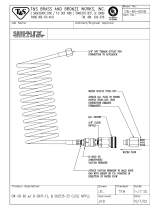
Servicing and repairs are made
considerably easier if the
powerhead is mounted on assembly
stand (1) 5910 890 3100. Remove
the chain sprocket cover, bar and
chain first.
The powerhead can then be
swivelled to the best position for the
VA
138RA001
1
ongoing repair. This leaves both
hands free.
Always use original STIHL
replacement parts.
They can be identified by the
STIHL part number,
the
67,+logo and the
STIHL parts symbol
This symbol may appear alone on
small parts.
1 Introduction

3034, 036, 036 QS
If the engine is started up in the
course of repairs or maintenance
work, observe all local and country-
specific safety regulations as well
as the safety precautions and
warnings in the owner’s manual.
Gasoline is an extremely flammable
fuel and can be explosive in certain
conditions.
Improper handling may result in
burns or other serious injuries.
Warning!
Do not smoke or bring any fire,
flame or other source of heat near
the fuel. All work with fuel must be
performed outdoors only. Spilled
fuel must be wiped away
immediately.
2 Safety Precautions

4 034, 036, 036 QS
3 Specifications
3.1 Engine
STIHL single cylinder two-stroke engine with special impregnated cylinder bore
034 036, 036 QS
Displacement:
Bore:
Stroke:
Compression ratio:
Engine power to ISO 8893:
Max. torque:
Max. permissible engine speed with
bar and chain:
Mean idle speed:
Crankshaft:
Main bearings:
Crankshaft journal diameter:
Big end bearing:
Piston pin diameter:
Small end bearing:
Connecting rod length:
Rewind starter:
Starter rope:
Clutch:
Diameter:
Clutch engages at:
Crankcase leakage test
at gauge pressure:
under vacuum:
56.5 cm
3
46 mm
34 mm
9.5:1
3.0 kW (4.1 bhp)
at 9,500 rpm
3.5 Nm
at 6,500 rpm
13,000 rpm
2,700 rpm
Two-part, drop forged
Two deep-groove ball bearings
14.4 mm
Needle cage
10 mm
Needle cage
58 mm
Pawl engagement with automatic
starter rope rewind mechanism
3.5 mm dia., 960 mm
Centrifugal clutch without linings
76 mm
approx. 3,500 rpm
0.5 bar
0.5 bar
61.5 cm
3
48 mm
34 mm
9.5:1
3.4 kW (4.6 bhp)
at 9,500 rpm
3.7 Nm
at 6,500 rpm
13,000 rpm
2,700 rpm
Two-part, drop forged
Two deep-groove ball bearings
14.4 mm
Needle cage
10 mm
Needle cage
58 mm
Pawl engagement with automatic
starter rope rewind mechanism
3.5 mm dia., 960 mm
Centrifugal clutch without linings
76 mm
approx. 3,500 rpm
0.5 bar
0.5 bar
3.2 Fuel System 034, 036, 036 QS
Carburetor:
Standard setting
High speed screw H:
Low speed screw L:
Idle setting:
Carburetor leakage test
at gauge pressure:
Fuel tank capacity:
Fuel mixture:
Mix ratio:
Air filter:
All positon diaphragm carburetor
with integral fuel pump
approx. 1 turn open
approx. 1 turn open
(starting with screws firmly against
their seats)
0.4 bar
625 cm
3
Regular brand-name gasoline and
brand-name two-stroke engine oil
50:1 with STIHL two-stroke engine
oil
25:1 with other brand-name two-
stroke, air-cooled engine oils
Large area, bisectional box filter
with wire mesh

5034, 036, 036 QS
3.3 Ignition System
Type:
Air gap:
Spark plug (suppressed):
Electrode gap:
Spark plug thread:
Thread length:
Heat range:
034, 036, 036 QS
Transistorized magneto ignition
(breakerless)
0.2 - 0.3 mm
Bosch WSR 6 F
0.5 mm
M14x1.25
9.5 mm
200
3.4 Cutting Attachment
Guide bars:
Cutting lengths:
Oilomatic chain:
Chain sprockets:
Chain speed:
Chain lubrication:
Oil delivery rate:
Oil tank capacity:
STlHL Rollomatic S bars with nose
sprocket.
STlHL Duromatic bars with stellite-
tipped nose.
Both types with corrosion-resistant
finish and induction hardened rails.
Rollomatic 37, 40, 45 and 50 cm
Duromatic 37, 40, 45 and 50 cm
9.32 mm (3/8") Rapid-Micro,
Rapid-Super
(Options: 8.25 mm (0.325")
Rapid-Micro, Rapid-Super,
Topic-Micro and Topic-Super)
7-tooth, 3/8" rim sprocket
20.7 m/s at 9,500 rpm (with 7-tooth,
3/8" sprocket)
Fully automatic, speed-controlled
reciprocating oil pump; no oil feed
at idle speed. Additional manual oil
flow control
Adjustable 5.5 - 15.5 cm
3
/min
at 10,000 rpm
320 cm
3

6 034, 036, 036 QS
3.5 Tightening Torques
DG and P (Plastoform) screws are used in polymer and lightmetal components. These screws form a
permanent thread when they are installed for the first time. They can be removed and installed as often as
necessary without impairing the strength of the screwed assembly, providing the specified tightening torque is
observed.
For this reason it is essential to use a torque wrench.
Fastener Thread size For component Torque
Nm
Remarks
Pan head screw M4x8 Chain tensioner cover plate 3.0
M7x12.5 Starter post to fan housing 12.0 1)
Screw M8x22 Brake band/crankcase
(036 QS II) 10.0 2)
Self-tapping screw B3.9x13 Brake cable retainer/tank housing (036 QS II) 1.5
Collar screw M8x21.5 Guide bar 23.0 2)
Spline screw IS-M4x12 Cover, chain brake/crankcase 3.0
M10x1 Decompression valve (036, 036 QS) 14.0
Spline screw M3.5x12 Generator (W version) 2.0 3)
Spline screw IS-P6x21.5 Front handle/tank housing, top right
(W version) 7.0 3)
Spline screw IS-P6x19 Front handle/tank housing, bottom
(W version) 7.0 3)
Spline screw IS-P6x32,5 Front handle/tank housing, top right, polymer 5.0 3)
Spline screw IS-P6x21,5 Front handle/tank housing, bottom, polymer 5.0 3)
Spline screw IS-P4x19 Handle molding 1.6
Screw assembly M5x30 Hand guard, left 7.0 2)
Spline screw IS-P6x19 Chain catcher 2.8
Spline screw IS-M5x12 Spiked bumber 7.5
Spline screw IS-M5x20 Crankcase 9.0
Spline screw IS-M5x20 Fan housing/crankcase 7.0
M12x1 L Carrier 50.0
Screw HL6x18.5 Annular buffer to rear left/right of tank housing 5.0
Spline screw IS-P6x19 Annular buffer to front right of tank housing 5.0
Spline screw IS-M5x6 Muffler, upper/lower casing 6.5 2)
Spline screw IS-M5x25 Muffler/crankcase 10.0 2)
Spline screw IS-M5x16 Muffler/cylinder (036, 036 QS) 10.0 2)
Spline screw IS-M5x25 Muffler/crankcase (034) 10.0 4)
Spline screw IS-M5x20 Muffler/cylinder (034) 10.0 4)
Spline screw IS-M5x22 Muffler/cylinder (034/Z version) 10.0 4)
Slotted nut M5 Shroud 3.3
Slotted nut M5 Air filter 2.0
M8x1 Flywheel 33.0 6)
Setscrew M5x8.5 Setscrew, l/h side of cylinder 1.4 5)
Setscrew M5x8.5 Setscrew, r/h side of cylinder 1.4

7034, 036, 036 QS
Hexagon nut M5 Carburetor (initial) 2.0
Hexagon nut M5 Carburetor (final) 3.5
Spline screw IS-M5x20 Cylinder/crankcase (036, 036 QS) 11.5
Spline screw IS-M5x20 Cylinder/crankcase (034) 10.5
M14x1.25 Spark plug 25.0
Spline screw IS-M5x20 Ignition module (with washer) 8.0 2)
Spline screw IS-M4x12 Oil pump/crankcase 3.5
1) Micro-encapsulated
2) Threadlocking method: medium strength adhesive (e.g. LOCTITE 243)
3) Threadlocking method: high strength adhesive (e.g. LOCTITE 649)
4) Threadlocking method: high strength adhesive up to 250°C (e.g. LOCTITE 272)
5) Threadlocking method: high strength adhesive (e.g. LOCTITE 270)
6) Degrease taper with cleaning agent (e.g. Somentor 33)
Use the following procedure when refitting a DG or P screw in an existing thread:
– Place the screw in the hole and rotate it counterclockwise until it drops down slightly.
– Tighten the screw clockwise to the specified torque.
This procedure ensures that the screw engages properly in the existing thread and does not form a new thread
and weaken the assembly.
Note:
Power screwdriver settings for polymer:
– Plastoform screws max. 600 rpm
– DG screws max. 500 rpm
3.6 Special Accessories
3.6.1 For User
3.6.2 For Service
Intake air preheating kit
Intake air preheating kit
.325", 8-tooth rim sprocket kit
.325", 7-tooth rim sprocket kit
3/8", 7-tooth rim sprocket kit
3/8", 7-tooth spur sprocket
.325", 7-tooth spur sprocket
Gasket set
Carburetor parts kit
Gasket panel
034, 036, 036 QS
1125 007 1035 (036)
1125 007 1004 (034/034S)
1125 007 1000
1125 007 1001
1125 007 1002
1125 640 2000
1125 640 2005
1125 007 1050
1128 007 1065
0457 281 0604
Fastener Thread size For component Torque
Nm
Remarks

8 034, 036, 036 QS
Troubleshooting chart - see
"Standard Repairs, Trouble-
shooting" handbook.
Unscrew nuts (1) from chain
sprocket cover (2). Remove the
sprocket cover, bar and chain (3).
VA
138RA002
1
2
3
Disengage the chain brake by
pulling the hand guard toward the
front handle.
VA
143RA004
Remove the E-clip (1) and
washer (2). If a rim sprocket (3)
is fitted, pull it off.
VA
148RA061
3
21
036 QS
Disengage the additional brake
by pressing down the throttle
trigger and interlock lever.
Remove the clutch drum (1) and
needle cage (2).
VA
148RA062
1
2
034, 036
Pull off the chain sprocket (1) or
clutch drum (2).
– Take out the needle cage.
VA
138RA003
1
2
Inspect the clutch drum (1).
There should be no scores or
signs of excessive wear.
Important:
If there are signs of serious wear on
the inside diameter of the clutch
drum (1), check the remaining wall
VA
148RA101
80%
100%
1
!
thickness. If it is less than about
80% of the original thickness, fit a
new clutch drum.
Note:
Clean stub of crankshaft. Wash
needle cage, examine it for damage
and replace if necessary. Lubricate
needle cage with STIHL multi-
purpose grease - see 13.2.
Reassemble in the reverse
sequence - start by fitting the needle
cage on the crankshaft stub.
4 Clutch, Chain Drive,
Chain Brake and
Chain Tensioner
4.1 Clutch Drum and Chain Sprocket

9034, 036, 036 QS
– Remove chain sprocket cover -
see 4.1.
Take out screw (1) and remove
the inner side plate (2).
Take out screw (3) and remove
the chain catcher (4).
VA
148RA063
2
1
3
4
Reassemble in the reverse
sequence.
Troubleshooting chart - see
"Standard Repairs, Trouble-
shooting" handbook.
– Remove clutch drum/chain
sprocket - see 4.1.
Release twist lock (1) on
carburetor box cover (2) and lift
cover off vertically.
VA
148RA064
1
2
Note:
When reassembling, check
correct position of groove and
guide.
VA
148RA065
Unscrew the slotted nut (1).
– Pull boot off the spark plug.
Remove the shroud (2).
VA
148RA066
2
1
On powerheads with a
decompression valve (1), remove
the cover and unscrew the
decompression valve.
Unscrew the spark plug (2).
VA
148RA067
1
2
Push the locking strip (1)
0000 893 5903 into the cylinder
so that the words "OBEN - TOP"
face upward.
VA
148RA069
1
4.2 Replacing the
Chain Catcher
4.3 Clutch

10 034, 036, 036 QS
Unscrew the clutch clockwise
from the crankshaft (left-hand
thread).
On 036, 036 QS:
Remove cover washer from the
crankshaft stub.
VA
148RA068
– Disassemble and reassemble the
clutch - see "Standard Repairs,
Troubleshooting" handbook.
– Reassemble in the reverse
sequence.
Note:
Observe tightening torque for clutch
(see "Tightening Torques").
Troubleshooting chart - see
"Standard Repairs, Trouble-
shooting" handbook.
– Remove the chain sprocket cover
and cutting attachment - see 4.1.
– Remove the clutch drum/chain
sprocket - see 4.1
Remove mounting screw (1) from
inner side plate (2) and lift side
plate away.
– Engage the chain brake by
pushing the hand guard away
from the front handle.
VA
138RA004
1
2
Remove mounting screws (1)
from cover (2) and lift the cover
away.
VA
138RA005
1
1
1
2
Carefully pry the brake spring (1)
off the anchor pin and disconnect
it from the lever (2).
VA
138RA006
1
2
Ease the brake band (1) out of
its seat in the crankcase and
disconnect it from the lever (2).
VA
138RA007
1
2
Remove screw with captive
washer from the hand guard.
Note:
When installing, tighten down the
screw with captive washer firmly
(see "Tightening Torques").
VA
138RA008
4.4 Chain Brake (034, 036)
4.4.1 Removing

11034, 036, 036 QS
Remove the E-clip from the pivot
pin.
– Pull the hand guard and lever
from the pivot pins.
VA
138RA009
– Pull the lever out of the hand
guard.
Remove the E-clip (3) from pivot
pin of lever (2) and detach the
spring (1).
Remove the cam lever and
VA
138RA010
1
2
3
spring.
– Clean all disassembled parts in
white spirit. Replace any worn or
damaged parts.
Fit the cam lever (2) and
spring (1).
– Fit the E-clip.
VA
1
2
138RA011
Insert lever in the side of the hand
guard so that short arm of lever
points up.
Note:
Check correct installed position of
lever.
VA
138RA012
Position the hand guard (1)
against the pivot pin and fit the
other side of the hand guard over
the fan housing.
VA
138RA013
1
Press the cam lever slightly
downward and push the hand
guard and lever onto the pivot
pins.
– Secure lever with E-clip.
– Insert hand guard mounting
VA
138RA014
screw with captive washer at fan
side and tighten down firmly (see
"Tightening Torques")
Important:
Coat all sliding and bearing points
with STIHL multipurpose grease,
see 13.2, or (better) with
molybdenum grease (e.g.
Molykote), see 13.2.
Do not lubricate the brake band.
First attach the brake band (1) to
the lever (2) and then push it into
the crankcase recess (arrow).
VA
138RA007
1
2
4.4.2 Installing

12 034, 036, 036 QS
Check that protective tube is
correctly positioned:
a = 20 mm
b = 33 mm
b
a
VA
138RA016
Hook the brake spring to the
lever.
VA
138RA017
Use the assembly tool
1117 890 0900 to attach the
brake spring (1) to the anchor pin.
– Fit cover over the chain brake.
VA
138RA015
1
– Fit the inner side plate - see 4.1.
– Install the clutch drum/chain
sprocket - see 4.1.
– Fit the cutting attachment and
chain sprocket cover - see 4.1.
Troubleshooting chart - see
"Standard Repairs, Trouble-
shooting" handbook.
– Remove the chain sprocket cover
and cutting attachment - see 4.1.
– Remove clutch drum/chain
sprocket - see 4.1.
Remove mounting screw (1) from
inner side plate (2) and lift side
plate away.
Remove mounting screws (3)
from cover (4) and lift the cover
away.
VA
148RA070
4
2
3
3
3
1
– Engage the chain brake by
pushing the hand guard away
from the front handle.
4.5 Chain Brake (036 QS)
4.5.1 Removing

13034, 036, 036 QS
Carefully pry the brake spring (1)
off the anchor pin and disconnect
it from the lever (2).
VA
148RA071
1
2
Remove the screw (1).
Ease the brake band (2) out of
its seat in the crankcase and
disconnect it from the lever (3).
3
2
1
VA
148RA072
Remove screw with captive
washer from the hand guard.
Note:
When installing, tighten down the
screw with captive washer firmly
(see "Tightening Torques").
VA
138RA008
Carefully pry spring (1) off the
pivot pin.
VA
148RA073
1
Pull the hand guard (2) and brake
lever (1) off the pivot pins.
VA
148RA074
2
1
Disconnect brake cable (1) from
the brake lever (2).
– Take the brake lever out of the
hand guard.
VA
148RA075
2
1
Disconnect spring (1) from
lever (2).
Pry the E-clip (3) off the pivot pin
and remove the lever with spring.
Clean all disassembled parts in
VA
148RA076
1
2
3
white spirit. Replace any worn or
damaged parts.

14 034, 036, 036 QS
Fit the lever (2) and spring (1).
Fit the E-clip (3).
VA
148RA076
1
2
3
Insert lever in the side of the hand
guard as shown.
VA
148RA077
Attach brake cable (1) to hole
(arrow) in brake lever (2).
VA
148RA075
2
1
Position the hand guard (1)
against the pivot pin and fit the
other side of the hand guard over
the fan housing.
Press the lever (1) slightly
downward and push the hand
guard and brake lever (2) onto
VA
148RA078
1
2
the pivot pins.
– Insert screw with captive washer
for hand guard and tighten down
firmly (see "Tightening Torques").
Important:
Coat all sliding and bearing points
with STIHL multipurpose grease,
see 13.2, or (better) with
molybdenum grease (e.g.
Molykote), see 13.2.
Do not lubricate the brake band.
Attach spring (1) to the pivot pin.
VA
148RA073
1
First attach the brake band (2) to
the brake lever (3) and then push
it into the slot in the crankcase.
Install screw (1) with LOCTITE
243 and tighten down firmly (see
"Tightening Torques")
3
2
1
VA
148RA072
Hook the brake spring (1) to the
brake lever (2).
VA
148RA071
1
2
4.5.2 Installing

15034, 036, 036 QS
Use the assembly tool
1117 890 0900 to attach the
brake spring (1) to the anchor pin.
– Fit cover over the chain brake -
see 4.5.1.
– Fit inner side plate - see 4.5.1.
VA
148RA098
1
– Install the clutch drum/chain
sprocket - see 4.1.
– Fit the cutting attachment and
chain sprocket cover - see 4.1.
– Pull hand guard toward front
handle.
– Unscrew nut from chain sprocket
cover and remove the cover - see
4.1.
– Remove the cutting attachment -
see 4.1.
Take out screw (1) and remove
the side plate (2).
Take out screws (3) and remove
the cover (4).
VA
148RA070
4
2
3
3
3
1
The brake cable (1) must hang
loosely in the crankcase when
the brake is disengaged.
VA
148RA079
1
Press down interlock lever (1) all
the way and hold it in that
position.
VA
148RA080
1
The brake band (1) must locate
without any play against the
points (A) in the crankcase.
VA
148RA081
A
A
A
A
A
1
A
Let go of the interlock lever (1).
Check free travel by slowly
squeezing the interlock lever (1).
Play must be within the mark (B)
at the front end of the interlock
lever.
VA
148RA082
1
B
4.5.3 Checking Play

16 034, 036, 036 QS
The brake lever must not move. If
it does, adjust play - see 4.5.4
Reassemble in the reverse
sequence.
Open twist lock (1) and lift away
the carburetor box cover (2)
vertically.
VA
148RA064
1
2
Release and unscrew slotted
nuts (1).
Remove the air filter (2).
VA
148RA084
2
11
Loosen the self-tapping
screw (1).
Use a 6mm open-end wrench to
adjust play with nut (2).
VA
148RA085
1
2
Turn wrench to right to reduce
play.
Turn wrench to left to increase
play.
Lock the setting with self-tapping
screw (1).
Reassemble in the reverse
sequence.
4.5.4 Adjusting Play

17034, 036, 036 QS
Check operation of the chain brake
with the bar and chain mounted.
Note:
When starting the machine observe
local safety regulations and the
safety precautions in the owner’s
manual.
– With the engine running, open
the throttle wide.
– Release the rear handle.
The chain must come to a standstill
in less than one second.
If the brake does not operate
properly, service the sliding and
bearing points shown in the
illustrations as follows:
If lightly contaminated:
– Clean all parts with a brush and
white spirit.
If heavily contaminated or
clogged with resin:
– Remove the parts concerned and
clean in white spirit or a resin
solvent.
– Replace worn or damaged parts.
– Before re-installing parts, the
machine recesses and seats.
Lubricate bearing points with
Mobilplex grease (see 13.2).
VA
148RA047
Lubricate these points (1) with
Mobilplex grease (see 13.2).
Coat outside diameter of clutch
drum (2) with chain oil.
Note:
If a biological chain oil is preferred,
VA
148RA048
1
1
2
2
STIHL recommends the use of
rapidly biodegradable STIHL
Bioplus.
To guarantee troublefree operation,
use only original STIHL replace-
ment parts as per the latest parts
list.
– Remove chain sprocket cover
and cutting attachment - see 4.1.
Remove mounting screw (1) from
inner side plate (2) and lift side
plate away.
VA
138RA004
1
2
Use a screwdriver to turn the spur
gear clockwise until tensioner
slide butts against the thrust pad.
Note:
Older machines are equipped with
a front chain tensioner - see 5.5.2.
148RA086
VA
4.5.5 Checking Operation of Chain Brake 4.6 Chain Tensioner

18 034, 036, 036 QS
Take out the cover plate
mounting screw (1).
Remove the cover plate (2) with
retainer (3) from the spur gear.
148RA087
VA
3
1 2
Pull out the spur gear (1).
Take out the tensioner slide (3)
with adjusting screw (4) and
thrust pad (2).
– Inspect the teeth on the spur gear
and adjusting screw, remove
VA
4 3
1
2
148RA088
thrust pad if necessary.
– Take the adjusting screw out of
the tensioner slide and replace
the parts.
Install in the reverse sequence.
Check that O-ring is fitted in spur
gear.
– Lubricate O-ring with a little oil
before fitting the spur gear.
Note:
Coat teeth of adjusting screw and
VA
138RA018
spur gear with grease, see 13.2,
before refitting.
The adjusting screw and spur gear
must be replaced as a matching
pair.
– Remove chain sprocket cover
and cutting attachment - see 4.1.
Push stud puller 5910 893 0501
over the collar stud as far as it will
go. Use a 15 mm wrench to
unscrew the collar stud counter-
clockwise.
VA
138RA019
– Before installing, coat thread of
collar stud with LOCTITE - see
13.2.
– Install and tighten down the collar
studs (see "Tightening Torques").
4.7 Bar Mounting Studs

19034, 036, 036 QS
Always check and, if necessary,
repair the fuel system, carburetor,
air filter and ignition system before
looking for faults on the engine.
Troubleshooting chart - see
"Standard Repairs, Trouble-
shooting" handbook.
(034)
Take out the screws and remove
the upper casing.
VA
138 RA 219
(036, 036 QS)
Take out screws and remove the
upper casing.
VA
138 RA 220
Take out the screws and remove
the lower casing.
VA
138 RA 020
(034)
Remove exhaust gasket (1) and
flange.
VA
138RA021
1
(036, 036 QS)
Remove heat shield (1) and
gasket (2) from the upper
casing (3).
VA
138RA022
1
3
2
Install new gasket (1) so that its
bead points toward the muffler.
Note:
If the bores of the lower casing are
not reinforced, fit washers under the
heads of the mounting screws.
VA
138RA021
1
– Coat threads of mounting screws
with LOCTITE - see 13.2.
– Insert and tighten down the
mounting screws firmly (see
"Tightening Torques").
5Engine
5.1 Removing and Installing Muffler

20 034, 036, 036 QS
Always check and, if necessary,
repair the fuel system, carburetor,
air filter and ignition system before
looking for faults on the engine.
Troubleshooting chart - see
"Standard Repairs, Trouble-
shooting" handbook.
– Drain the fuel and oil tanks.
– Remove the air filter - see 12.1
– Remove the carburetor - see 12.3
Pull the washer (1) off the studs
and remove the sleeve (2) from
the manifold.
– Remove the shroud, spark plug
and, if fitted, the decompression
valve - see 4.3.
VA
138RA023
1
2
– Remove the muffler - see 5.1
Reassemble in the reverse
sequence.
– Preparations - see 5.2
Take out the four cylinder base
screws.
VA
148RA089
Pull the cylinder off the piston
and, at the same time, push the
manifold through the tank
housing opening.
Caution:
Do not use pointed or sharp-edged
tools for this job.
VA
138RA024
Remove the cylinder gasket.
VA
138RA025
Release the hose clamp (1) on
the manifold (2). Pull the manifold
off the intake port.
– Inspect the cylinder and replace it
if necessary.
Note:
VA
138RA026
12
If a new cylinder has to be installed,
always fit the matching piston. New
cylinders are only supplied
complete with piston for this reason.
5.2 Exposing the Cylinder 5.3 Cylinder and Piston
5.3.1 Removing
/