RAB Lighting ND6S26D/E2 Operating instructions
- Type
- Operating instructions

NDLED6 INSTALLATION INSTRUCTIONS
Thank you for buying RAB lighting xtures. Our goal is to design the best quality products to get the job done right. We’d like to hear your comments.
Call the Marketing Department at 888-RAB-1000 or email: marketing@rabweb.com
IMPORTANT
READ CAREFULLY BEFORE INSTALLING FIXTURE. RETAIN THESE INSTRUCTIONS FOR FUTURE REFERENCE.
RAB xtures must be wired in accordance with the National Electrical Code and all applicable local codes. Proper grounding
is required for safety. THIS PRODUCT MUST BE INSTALLED IN ACCORDANCE WITH THE APPLICABLE INSTALLATION CODE BY A
PERSON FAMILIAR WITH THE CONSTRUCTION AND OPERATION OF THE PRODUCT AND THE HAZARDS INVOLVED.
WARNING: Make certain power is OFF before installing or maintaining xture. No user serviceable parts inside.
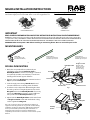
MOUNTING BARS
A
A
B B
C C
D D
4
1234
23
R
AB
SCALE 1.000
L I G H T I N G 170 LUDLOW AVE., NORTHVALE, NJ 07647
TITLE
13" NAILER BAR ASSEMBLY M & F
MATERIAL: PART No.: DRAWING NAME:
SEE NOTES 15153 15153 NAILER BAR ASSY
DATE: REV DATE: REV
3-9-12
DRAWN BY:
DH
SCALE
FULL
SHEET:
THIS DRAWING AND THE INFORMATION IT DISCLOSES IS THE EXCLUSIVE
PROPERTY OF RAB LIGHTING, INCORPORATED
ANY REPRODUCTION OR USE OF THIS DRAWING WITHOUT THE WRITTEN CONSENT OF
RAB LIGHTING, INC. IS STRICTLY PROHIBITED. RAB CONFIDENTIAL PATENT PENDING
REV DESCRIPTION DATE
1
13.375" REF
QUOTATION DRAWING
NOTES:
1. PART TO BE SUPPLIED BY TRIPAR INDUSTRIES
PART NUMBER 1287
2. MATERIAL: GALVANIZED STEEL
SCALE 1.000
A
A
B B
C C
D D
4
1234
23
R
AB
SCALE 0.500
L I G H T I N G 170 LUDLOW AVE., NORTHVALE, NJ 07647
TITLE
27" C-CHANNEL
MATERIAL: PART No.: DRAWING NAME:
22 GA EC STL 15154-27 15154-27 C-CHANNEL
DATE: REV DATE: REV
3-9-12
DRAWN BY:
DH
SCALE
1/2
SHEET:
THIS DRAWING AND THE INFORMATION IT DISCLOSES IS THE EXCLUSIVE
PROPERTY OF RAB LIGHTING, INCORPORATED
ANY REPRODUCTION OR USE OF THIS DRAWING WITHOUT THE WRITTEN CONSENT OF
RAB LIGHTING, INC. IS STRICTLY PROHIBITED. RAB CONFIDENTIAL PATENT PENDING
REV DESCRIPTION DATE
1
QUOTATION DRAWING
11-14-12
SCALE 0.500
.500
[12,7]
1.500
[38,1]
27.000
[685,8]
.201 (2)
[5,11]
.250
[6,35]
.220
[5,59]
A
A
B B
C C
D D
4
1234
23
R
AB
SCALE 0.500
L I G H T I N G 170 LUDLOW AVE., NORTHVALE, NJ 07647
TITLE
27" C-CHANNEL
MATERIAL: PART No.: DRAWING NAME:
22 GA EC STL 15154-27 15154-27 C-CHANNEL
DATE: REV DATE: REV
3-9-12
DRAWN BY:
DH
SCALE
1/2
SHEET:
THIS DRAWING AND THE INFORMATION IT DISCLOSES IS THE EXCLUSIVE
PROPERTY OF RAB LIGHTING, INCORPORATED
ANY REPRODUCTION OR USE OF THIS DRAWING WITHOUT THE WRITTEN CONSENT OF
RAB LIGHTING, INC. IS STRICTLY PROHIBITED. RAB CONFIDENTIAL PATENT PENDING
REV DESCRIPTION DATE
1
QUOTATION DRAWING
11-14-12
SCALE 0.500
.500
[12,7]
1.500
[38,1]
27.000
[685,8]
.201 (2)
[5,11]
.250
[6,35]
.220
[5,59]
NDLED6R NDLED6S
Cut-Out Diameter: 7” Cut-Out: 7”x7”
Nailer Bar
13” adjustable to 24”
(provided with xture)
C Channel-51”
(order Cat #: C-Chan 51)
Available upon request
C Channel-27”
(order Cat #: C-Chan 27)
Available upon request
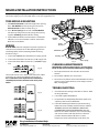
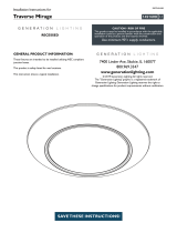
ROUGHIN MOUNTING
1. Nailer bars are provided for use with wood joist
installations. Insert through Nailer Bar Slots in
Buttery Brackets and secure accordingly. C-Channels
are optionally available, consult factory. Consult local
building codes for nal support of xture.
2. Remove appropriate Knock out on Junction box. Press
Clip to open the Junction Box.
3. Feed the supply wires through Knock out hole and
connect to the driver. See wiring section for details.
4. The xture can be adjusted to dierent heights above
the ceiling surface. For height adjustment, loosen the
Wing Nut and slide the Buttery Bracket. If necessary
remove the Wing Nut and insert in screw in dierent
hole provided on the Buttery Bracket. (Fig: 2)
5. Adjust both the Buttery Brackets such that the frame
of Rough-In Section is ush with the nished ceiling
surface. Tighten the Wing nuts.
A
A
B B
C C
D D
4
1234
23
R A B
L I G H T I N G 170 LUDLOW AVE., NORTHVALE, NJ 07647
TITLE
MATERIAL: PART No.: DRAWING NAME:
DATE: REV DATE: REV
DRAWN BY: SCALE SHEET:
THIS DRAWING AND THE INFORMATION IT DISCLOSES IS THE EXCLUSIVE
PROPERTY OF RAB LIGHTING, INCORPORATED
ANY REPRODUCTION OR USE OF THIS DRAWING WITHOUT THE WRITTEN CONSENT OF
RAB LIGHTING, INC. IS STRICTLY PROHIBITED. RAB CONFIDENTIAL PATENT PENDING
ECN #
REV DESCRIPTION DATE
Init.
1
TOLERANCES
.X .02
.XX .01
.XXX .005
ANGLES .5
SCALE 0.500
A
A
B B
C C
D D
4
1234
23
R A B
L I G H T I N G 170 LUDLOW AVE., NORTHVALE, NJ 07647
TITLE
MATERIAL: PART No.: DRAWING NAME:
DATE: REV DATE: REV
DRAWN BY: SCALE SHEET:
THIS DRAWING AND THE INFORMATION IT DISCLOSES IS THE EXCLUSIVE
PROPERTY OF RAB LIGHTING, INCORPORATED
ANY REPRODUCTION OR USE OF THIS DRAWING WITHOUT THE WRITTEN CONSENT OF
RAB LIGHTING, INC. IS STRICTLY PROHIBITED. RAB CONFIDENTIAL PATENT PENDING
ECN #
REV DESCRIPTION DATE
Init.
1
TOLERANCES
.X .02
.XX .01
.XXX .005
ANGLES .5
SCALE 0.500
Rough-in Section
(Bottom of the
Rough-in Section
to be ush with
nished ceiling)
Buttery Brackets
Male Connector
Knock Out
Clip
Junction Box
Fig: 1
Buttery
Bracket
Wing Nut
Fig: 2
Nailer Bar Slot
Note: These instructions do not cover all details or variations in
equipment nor do they provide for every possible situation during
installation, operation or maintenance. RAB cannot troubleshoot
Lutron systems and have provided only basic information. See
www.lutron.com for complete instructions and functional
compatibility of Lutron Drivers with Lutron or other Control systems/
dimmers.

NDLED6 INSTALLATION INSTRUCTIONS
Thank you for buying RAB lighting xtures. Our goal is to design the best quality products to get the job done right. We’d like to hear your comments.
Call the Marketing Department at 888-RAB-1000 or email: marketing@rabweb.com
TROUBLESHOOTING
1. Check that the line voltage at the xture is correct. Refer
to wiring directions.
2. Is the xture grounded properly?
3. For questions on compatibility of dimmers purchased
separately refer to www.rabweb.com
4. If the LED is blinking the xture may be overheating.
Remove the Trim assembly and if the xture is labeled
‘BLINKING LIGHT OF THIS THERMALLY PROTECTED
LUMINAIRE MAY INDICATE OVERHEATING’ allow the
xture to cool down. Determine cause of overheating
and remove. Fixtures with this label have a thermal
protector that turns xture o above a certain
temperature. It will automatically restart when cool.
CLEANING & MAINTENANCE
CAUTION: Be sure xture temperature is cool enough to
touch. Do not clean or maintain while xture is energized.
1. Do not open xture to clean the LED. Do not touch
the LED.
2. Do not touch reector, lens, or trim cone.
3. Do not clean any xture surface with wood base cleaning
material such as paper towels or tissues. Only use micro
ber cleaning cloth.
Easy Installation & Product Help
Tech Help Line
Call our experts 888 RAB-1000
©2014 RAB LIGHTING Inc.
No
rthvale, New Jersey 07647 USA
rabweb.com
Visit our website for product info
email
Answered promptly sales@rabweb.com
NDLED6 IN-1114
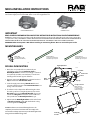
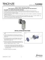
TRIM MODULE MOUNTING
1. Pull Female Connector conduit through frame opening.
Raise Trim Module towards opening and connect to
Male Connector conduit as shown in Fig. 3.
2. Press Torsion Springs inward and slide Trim Module
info frame opening. Release both springs into opening
together. Trim Ring should be ush to ceiling.
3. For the Wallwash Model, orient the xture such that the
reector is in correct orientation. Look for ‘Towards the
Wall’ label on the xture.
A
A
B B
C C
D D
4
1234
23
R A B
L I G H T I N G 170 LUDLOW AVE., NORTHVALE, NJ 07647
TITLE
MATERIAL: PART No.: DRAWING NAME:
DATE: REV DATE: REV
DRAWN BY: SCALE SHEET:
THIS DRAWING AND THE INFORMATION IT DISCLOSES IS THE EXCLUSIVE
PROPERTY OF RAB LIGHTING, INCORPORATED
ANY REPRODUCTION OR USE OF THIS DRAWING WITHOUT THE WRITTEN CONSENT OF
RAB LIGHTING, INC. IS STRICTLY PROHIBITED. RAB CONFIDENTIAL PATENT PENDING
ECN #
REV DESCRIPTION DATE
Init.
1
TOLERANCES
.X .02
.XX .01
.XXX .005
ANGLES .5
SCALE 0.500
Rough-in
Section
Trim Module
Male Connector
Torsion Spring
Trim Ring
Female
Connector
Fig: 3
WIRING
RISK OF FIRE. Universal voltage driver permits operation at
120V thru 277V, 50 or 60 Hz. For Non-Dimming, Electronic
Low Voltage (ELV) and Triac Dimming follow the wiring
directions in Fig. 4.
1. Connect the GROUND wire from xture to supply ground.
2. Connect the black xture lead to the (+) LINE supply lead.
3. Connect the white xture lead to the (-) COMMON supply
lead.
Lutron L3D Hi-Lume series drivers work with Lutron 3-Wire
Control (Fig. 5) or EcoSystem Digital Controls (Fig. 6).
Note: See www.lutron.com for complete instructions and functional
compatibility of Lutron drivers with Lutron or other control systems/
dimmers.
Fig: 4
Fig: 5
Fig: 6

NDLED6 INSTALLATION INSTRUCTIONS
Thank you for buying RAB lighting xtures. Our goal is to design the best quality products to get the job done right. We’d like to hear your comments.
Call the Marketing Department at 888-RAB-1000 or email: marketing@rabweb.com
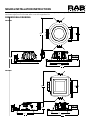
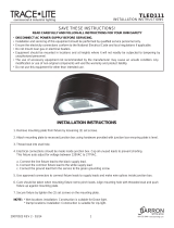
DIMENSIONAL DRAWING
NDLED6R
13.46
[341,9]
4.82
[122,5]
12.42
[315,4]
7.52
[190,9]
13.37
[339,6]
4.44
[112,7]
12.63
[320,8]
13.37
[339,6]
13.37
[339,6]
NDLED6S
Ø 7.52”
12.42”
4.82”
13.46”
12.63”
4.44”
13.37”
7.52”
7.52”

NDIC6 INSTALLATION INSTRUCTIONS
Thank you for buying RAB lighting xtures. Our goal is to design the best quality products to get the job done right. We’d like to hear your comments.
Call the Marketing Department at 888-RAB-1000 or email: marketing@rabweb.com
IMPORTANT
READ CAREFULLY BEFORE INSTALLING FIXTURE. RETAIN THESE INSTRUCTIONS FOR FUTURE REFERENCE.
RAB xtures must be wired in accordance with the National Electrical Code and all applicable local codes. Proper grounding
is required for safety. THIS PRODUCT MUST BE INSTALLED IN ACCORDANCE WITH THE APPLICABLE INSTALLATION CODE BY A
PERSON FAMILIAR WITH THE CONSTRUCTION AND OPERATION OF THE PRODUCT AND THE HAZARDS INVOLVED.
WARNING: Make certain power is OFF before installing or maintaining xture. No user serviceable parts inside.
MOUNTING BARS
A
A
B B
C C
D D
4
1234
23
R
AB
SCALE 1.000
L I G H T I N G 170 LUDLOW AVE., NORTHVALE, NJ 07647
TITLE
13" NAILER BAR ASSEMBLY M & F
MATERIAL: PART No.: DRAWING NAME:
SEE NOTES 15153 15153 NAILER BAR ASSY
DATE: REV DATE: REV
3-9-12
DRAWN BY:
DH
SCALE
FULL
SHEET:
THIS DRAWING AND THE INFORMATION IT DISCLOSES IS THE EXCLUSIVE
PROPERTY OF RAB LIGHTING, INCORPORATED
ANY REPRODUCTION OR USE OF THIS DRAWING WITHOUT THE WRITTEN CONSENT OF
RAB LIGHTING, INC. IS STRICTLY PROHIBITED. RAB CONFIDENTIAL PATENT PENDING
REV DESCRIPTION DATE
1
13.375" REF
QUOTATION DRAWING
NOTES:
1. PART TO BE SUPPLIED BY TRIPAR INDUSTRIES
PART NUMBER 1287
2. MATERIAL: GALVANIZED STEEL
SCALE 1.000
A
A
B B
C C
D D
4
1234
23
R
AB
SCALE 0.500
L I G H T I N G 170 LUDLOW AVE., NORTHVALE, NJ 07647
TITLE
27" C-CHANNEL
MATERIAL: PART No.: DRAWING NAME:
22 GA EC STL 15154-27 15154-27 C-CHANNEL
DATE: REV DATE: REV
3-9-12
DRAWN BY:
DH
SCALE
1/2
SHEET:
THIS DRAWING AND THE INFORMATION IT DISCLOSES IS THE EXCLUSIVE
PROPERTY OF RAB LIGHTING, INCORPORATED
ANY REPRODUCTION OR USE OF THIS DRAWING WITHOUT THE WRITTEN CONSENT OF
RAB LIGHTING, INC. IS STRICTLY PROHIBITED. RAB CONFIDENTIAL PATENT PENDING
REV DESCRIPTION DATE
1
QUOTATION DRAWING
11-14-12
SCALE 0.500
.500
[12,7]
1.500
[38,1]
27.000
[685,8]
.201 (2)
[5,11]
.250
[6,35]
.220
[5,59]
A
A
B B
C C
D D
4
1234
23
R
AB
SCALE 0.500
L I G H T I N G 170 LUDLOW AVE., NORTHVALE, NJ 07647
TITLE
27" C-CHANNEL
MATERIAL: PART No.: DRAWING NAME:
22 GA EC STL 15154-27 15154-27 C-CHANNEL
DATE: REV DATE: REV
3-9-12
DRAWN BY:
DH
SCALE
1/2
SHEET:
THIS DRAWING AND THE INFORMATION IT DISCLOSES IS THE EXCLUSIVE
PROPERTY OF RAB LIGHTING, INCORPORATED
ANY REPRODUCTION OR USE OF THIS DRAWING WITHOUT THE WRITTEN CONSENT OF
RAB LIGHTING, INC. IS STRICTLY PROHIBITED. RAB CONFIDENTIAL PATENT PENDING
REV DESCRIPTION DATE
1
QUOTATION DRAWING
11-14-12
SCALE 0.500
.500
[12,7]
1.500
[38,1]
27.000
[685,8]
.201 (2)
[5,11]
.250
[6,35]
.220
[5,59]
NDIC6R NDIC6S
Cut-Out Diameter: 7” Cut-Out: 7”x7”
Nailer Bar
13” adjustable to 24”
(provided with xture)
C Channel-51”
(order Cat #: C-Chan 51)
Available upon request
C Channel-27”
(order Cat #: C-Chan 27)
Available upon request
6.242
[158,55]
7.516
[190,91]
13.916
[353,47]
12.418
[315,43]
13.916
[353,47]
12.418
[315,43]
ROUGHIN MOUNTING
1. Nailer bars are provided for use with wood joist
installations. Insert through Nailer Bar Slots in
Buttery Brackets and secure accordingly. C-Channels
are optionally available, consult factory. Consult local
building codes for nal support of xture.
2. Remove appropriate Knock out on Junction box. Press
Clip to remove the Junction Box Cover.
3. Feed the supply wires through Knock out hole and
connect to the driver. Re-install Junction Box Cover. See
wiring section for details.
4. The xture can be adjusted to dierent heights above
the ceiling surface. For height adjustment, loosen the
Wing Nut and slide the Buttery Bracket. If necessary
remove the Wing Nut and insert in screw in dierent
hole provided on the Buttery Bracket. (Fig: 2)
5. Adjust both the Buttery Brackets such that the frame
of Rough-In Section is ush with the nished ceiling
surface. Tighten the Wing nuts.
6.242
[158,55]
7.516
[190,91]
13.916
[353,47]
12.418
[315,43]
13.916
[353,47]
12.418
[315,43]
Rough-in Section
(Bottom of the
Rough-in Section
to be ush with
nished ceiling)
Buttery Brackets
Male Connector
Knock Out
Clip
Junction Box
Cover
Fig: 1
Buttery
Bracket
Wing Nut
Fig: 2
Nailer
Bar Slot
RAB NDIC6 xtures are IC rated allowing xtures to be
completely covered with insulation and also comply with
minimum Air Leakage requirements per the Washington State
Energy Code and Model Energy Code.

NDIC6 INSTALLATION INSTRUCTIONS
Thank you for buying RAB lighting xtures. Our goal is to design the best quality products to get the job done right. We’d like to hear your comments.
Call the Marketing Department at 888-RAB-1000 or email: marketing@rabweb.com
TROUBLESHOOTING
1. Check that the line voltage at the xture is correct. Refer
to wiring directions.
2. Is the xture grounded properly?
3. For questions on compatibility of dimmers purchased
separately refer to www.rabweb.com
CLEANING & MAINTENANCE
CAUTION: Be sure xture temperature is cool enough to
touch. Do not clean or maintain while xture is energized.
1. Do not open xture to clean the LED. Do not touch
the LED.
2. Do not touch reector, lens, or trim cone.
3. Do not clean any xture surface with wood base cleaning
material such as paper towels or tissues. Only use micro
ber cleaning cloth.
Easy Installation & Product Help
Tech Help Line
Call our experts 888 RAB-1000
©2014 RAB LIGHTING Inc.
No
rthvale, New Jersey 07647 USA
rabweb.com
Visit our website for product info
email
Answered promptly sales@rabweb.com
NDIC6 IN-1214
TRIM MODULE MOUNTING
1. Pull Male Connector conduit through frame opening.
Raise Trim Module towards opening and connect to
Female Connector conduit as shown in Fig. 3.
2. Press Torsion Springs inward and slide Trim Module
info frame opening. Release both springs into opening
together. Trim Ring should be ush to ceiling.
3. For the Wallwash Model, orient the xture such that the
reector is in correct orientation. Look for ‘Towards the
Wall’ label on the xture.
6.242
[158,55]
7.516
[190,91]
13.916
[353,47]
12.418
[315,43]
13.916
[353,47]
12.418
[315,43]
Rough-in
Section
Trim Module
Male Connector
Torsion Spring
Female
Connector
Ceiling
Trim Ring
Fig: 3
WIRING
RISK OF FIRE. Universal voltage driver permits operation at
120V thru 277V, 50 or 60 Hz. For Non-Dimming, Electronic
Low Voltage (ELV) and Triac Dimming follow the wiring
directions in Fig. 4.
1. Connect the GROUND wire from xture to supply ground.
2. Connect the black xture lead to the (+) LINE supply lead.
3. Connect the white xture lead to the (-) COMMON supply
lead.
Lutron L3D Hi-Lume series drivers work with Lutron 3-Wire
Control (Fig. 5) or EcoSystem Digital Controls (Fig. 6).
Note: See www.lutron.com for complete instructions and functional
compatibility of Lutron drivers with Lutron or other control systems/
dimmers.
Fig: 4
Fig: 5
Fig: 6
Note: These instructions do not cover all details or variations in
equipment nor do they provide for every possible situation during
installation, operation or maintenance. RAB cannot troubleshoot
Lutron systems and have provided only basic information. See
www.lutron.com for complete instructions and functional
compatibility of Lutron Drivers with Lutron or other Control systems/
dimmers.

NDIC6 INSTALLATION INSTRUCTIONS
Thank you for buying RAB lighting xtures. Our goal is to design the best quality products to get the job done right. We’d like to hear your comments.
Call the Marketing Department at 888-RAB-1000 or email: marketing@rabweb.com
DIMENSIONAL DRAWING
NDIC6R
6.242
[158,55]
7.516
[190,91]
13.916
[353,47]
12.418
[315,43]
13.916
[353,47]
12.418
[315,43]
12.631
[320,82]
13.826
[351,18]
6.230
[158,23]
13.826
[351,18]
7.515
[190,88]
12.631
[320,82]
NDIC6S
13.92”
6.242
[158,55]
7.516
[190,91]
13.916
[353,47]
12.418
[315,43]
13.916
[353,47]
12.418
[315,43]
12.42”
12.42”
7.52”
13.92”
6.24”
12.631
[320,82]
13.826
[351,18]
6.230
[158,23]
13.826
[351,18]
7.515
[190,88]
12.631
[320,82]
12.631
[320,82]
13.826
[351,18]
6.230
[158,23]
13.826
[351,18]
7.515
[190,88]
12.631
[320,82]
13.83”
12..63”
7.52”
13.83”
6.23”
12.63”
Cut-Out
Diameter: 7”
Cut-Out
Dimension: 7”x7”

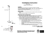
WIRING DIAGRAM for EMERGENCY OPERATION at 120V - 277V
Emergency Ballast and AC Ballast must be fed from the same circuit
+
-
BODINE
BSL17C-C2
EMERGENCY
LED DRIVER
INVERTER
CONNECTOR:
CONNECT ONLY AFTER
AC SUPPLY POWER IS
CONNECTED
CUSTOMER SHOULD
CONNECT ONLY
AFTER FINISHING
WIRING TO AC
POWER. BATTERY
COULD HAVE
CHARGE & SHOCK.
RAB LABEL - ADD
LED DRIVER
120V - 277V
COMMON
GROUND
SWITCH PLATE WITH
INTEGRAL TEST
SWITCH (INCLUDED)
SWITCH BOX
(BY OTHERS)
ELECTRONIC
BLOCK
PROTECTOR
JUNCTION BOX
JUNCTION
BOX
LED TRIM MODULE
RED
WHITE
BROWN
BROWN
VIOLET
VIOLET
ORANGE
- BLACK
STRIPE
WHITE
- RED
STRIPE
YELLOW
YELLOW - BLACK STRIPE
BLUE
WHITE - BLACK STRIPE
WHITE
BLACK
WHITE
BLUE -
OR
BLACK -
RED +
RED
RED
YELLOW
WHITE
YELLOW - BLACK STRIPE
BLACK
2' Flex Conduit Whip
8" Flex Conduit Whip
BLACK
UNSWITCHED
CONNECT TO
MAIN POWER
RAB LABEL -
ADD
BLACK
SWITCHED
IF NOT SWITCHED, THEN
CAP TOGETHER
RAB LABEL -
ADD
BLACK
BLUE
Easy Installation & Product Help
Tech Help Line
Call our experts 888 RAB-1000
©2012 RAB LIGHTING Inc.
Northvale, New Jersey 07647 USA
rabweb.com
Visit our website for product info
email
Answered promptly sales@rabweb.com
NDIC4 EM IN 1115

WIRING DIAGRAM for EMERGENCY OPERATION at 120V - 277V with Thermal Protector
Emergency Ballast and AC Ballast must be fed from the same circuit
+
-
BODINE
BSL17C-C2
EMERGENCY
LED DRIVER
INVERTER
CONNECTOR:
CONNECT ONLY AFTER
AC SUPPLY POWER IS
CONNECTED
CUSTOMER SHOULD
CONNECT ONLY
AFTER FINISHING
WIRING TO AC
POWER. BATTERY
COULD HAVE
CHARGE & SHOCK.
RAB LABEL - ADD
LED DRIVER
120V - 277V
COMMON
GROUND
SWITCH PLATE WITH
INTEGRAL TEST
SWITCH (INCLUDED)
SWITCH BOX
(BY OTHERS)
ELECTRONIC
BLOCK
PROTECTOR
JUNCTION BOX
JUNCTION
BOX
LED TRIM MODULE
RED
WHITE
BROWN
BROWN
VIOLET
VIOLET
ORANGE
- BLACK
STRIPE
WHITE
- RED
STRIPE
YELLOW
YELLOW - BLACK STRIPE
BLUE
WHITE - BLACK STRIPE
WHITE
BLACK
WHITE
BLUE -
OR
BLACK -
RED +
RED
RED
YELLOW
WHITE
YELLOW - BLACK STRIPE
BLACK
TP
TP
Thermal Protector
BLACKBLACK
2' Flex Conduit Whip
8" Flex Conduit Whip
BLACK
UNSWITCHED
CONNECT TO
MAIN POWER
RAB LABEL -
ADD
BLACK
SWITCHED
IF NOT SWITCHED, THEN
CAP TOGETHER
RAB LABEL -
ADD
BLACK
BLUE
Easy Installation & Product Help
Tech Help Line
Call our experts 888 RAB-1000
©2012 RAB LIGHTING Inc.
Northvale, New Jersey 07647 USA
rabweb.com
Visit our website for product info
email
Answered promptly sales@rabweb.com
NDIC4 EM IN 1115

NDIC6 EMERGENCY BATTERY BACKUP
INSTALLATION INSTRUCTIONS
Thank you for buying RAB lighting xtures. Our goal is to design the best quality products to get the job done right. We’d like to hear your comments.
Call the Marketing Department at 888-RAB-1000 or email: marketing@rabweb.com
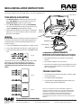
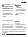
MOUNTING BARS
A
A
B B
C C
D D
4
1234
23
R
AB
SCALE 1.000
L I G H T I N G 170 LUDLOW AVE., NORTHVALE, NJ 07647
TITLE
13" NAILER BAR ASSEMBLY M & F
MATERIAL: PART No.: DRAWING NAME:
SEE NOTES 15153 15153 NAILER BAR ASSY
DATE: REV DATE: REV
3-9-12
DRAWN BY:
DH
SCALE
FULL
SHEET:
THIS DRAWING AND THE INFORMATION IT DISCLOSES IS THE EXCLUSIVE
PROPERTY OF RAB LIGHTING, INCORPORATED
ANY REPRODUCTION OR USE OF THIS DRAWING WITHOUT THE WRITTEN CONSENT OF
RAB LIGHTING, INC. IS STRICTLY PROHIBITED. RAB CONFIDENTIAL PATENT PENDING
REV DESCRIPTION DATE
1
13.375" REF
QUOTATION DRAWING
NOTES:
1. PART TO BE SUPPLIED BY TRIPAR INDUSTRIES
PART NUMBER 1287
2. MATERIAL: GALVANIZED STEEL
SCALE 1.000
A
A
B B
C C
D D
4
1234
23
R
AB
SCALE 0.500
L I G H T I N G 170 LUDLOW AVE., NORTHVALE, NJ 07647
TITLE
27" C-CHANNEL
MATERIAL: PART No.: DRAWING NAME:
22 GA EC STL 15154-27 15154-27 C-CHANNEL
DATE: REV DATE: REV
3-9-12
DRAWN BY:
DH
SCALE
1/2
SHEET:
THIS DRAWING AND THE INFORMATION IT DISCLOSES IS THE EXCLUSIVE
PROPERTY OF RAB LIGHTING, INCORPORATED
ANY REPRODUCTION OR USE OF THIS DRAWING WITHOUT THE WRITTEN CONSENT OF
RAB LIGHTING, INC. IS STRICTLY PROHIBITED. RAB CONFIDENTIAL PATENT PENDING
REV DESCRIPTION DATE
1
QUOTATION DRAWING
11-14-12
SCALE 0.500
.500
[12,7]
1.500
[38,1]
27.000
[685,8]
.201 (2)
[5,11]
.250
[6,35]
.220
[5,59]
A
A
B B
C C
D D
4
1234
23
R
AB
SCALE 0.500
L I G H T I N G 170 LUDLOW AVE., NORTHVALE, NJ 07647
TITLE
27" C-CHANNEL
MATERIAL: PART No.: DRAWING NAME:
22 GA EC STL 15154-27 15154-27 C-CHANNEL
DATE: REV DATE: REV
3-9-12
DRAWN BY:
DH
SCALE
1/2
SHEET:
THIS DRAWING AND THE INFORMATION IT DISCLOSES IS THE EXCLUSIVE
PROPERTY OF RAB LIGHTING, INCORPORATED
ANY REPRODUCTION OR USE OF THIS DRAWING WITHOUT THE WRITTEN CONSENT OF
RAB LIGHTING, INC. IS STRICTLY PROHIBITED. RAB CONFIDENTIAL PATENT PENDING
REV DESCRIPTION DATE
1
QUOTATION DRAWING
11-14-12
SCALE 0.500
.500
[12,7]
1.500
[38,1]
27.000
[685,8]
.201 (2)
[5,11]
.250
[6,35]
.220
[5,59]
Nailer Bar
13” adjustable to 24”
(provided with xture)
C Channel-27”
(order Cat #: C-Chan 27)
Available upon request
C Channel-51”
(order Cat #: C-Chan 51)
Available upon request
NDIC6R/E2 NDIC6S/E2
Cut-Out Diameter: 7” Cut-Out: 7” x7”
SAFETY INSTRUCTIONS
WARNING: Make certain power is OFF before installing or maintaining xture. No user serviceable parts inside.
WARNING: Suitable for wet locations where the ambient temperature is 0° C minimum, +40° C maximum.
WARNING: Suitable for installation in Insulated Ceilings only.
IMPORTANT
SUITABLE FOR INSTALLATION IN NON-ACCESSIBLE CEILINGS ONLY.
READ CAREFULLY BEFORE INSTALLING FIXTURE. RETAIN THESE INSTRUCTIONS FOR FUTURE REFERENCE.
Fixtures must be wired in accordance with the National Electrical Code and all applicable local codes. Proper grounding is required
for safety. THIS PRODUCT MUST BE INSTALLED IN ACCORDANCE WITH THE APPLICABLE INSTALLATION CODE BY A PERSON
FAMILIAR WITH THE CONSTRUCTION AND OPERATION OF THE PRODUCT AND THE HAZARDS INVOLVED.
THIS IS AN EMERGENCY BATTERY BACKUP FIXTURE THAT CONTAINS A RECHARGEABLE NICKEL-CADMIUM BATTERY. THE
BATTERY MUST BE RECYCLED OR DISPOSED OFF PROPERLY.
OPERATION
1. When AC power is applied, the charging indicator light is illuminated, indicating that the battery is being charged.
2. When power fails, the emergency ballast automatically switches to emergency power (internal battery), operating at reduced
illumination. The emergency ballast supplies 7W of power (measured at nominal battery voltage) at a maximum rated current
of 270mA with a maximum voltage of 50VDC in emergency mode for a minimum of 90 minutes.
3. When AC power is restored, the emergency ballast automatically returns to charging mode.
RAB NDIC6 xtures are IC rated allowing xtures to be completely covered with insulation and also comply with minimum Air Leakage
requirements per the Washington State Energy Code and Model Energy Code.

NDIC6 EMERGENCY BATTERY BACKUP
INSTALLATION INSTRUCTIONS
Thank you for buying RAB lighting xtures. Our goal is to design the best quality products to get the job done right. We’d like to hear your comments.
Call the Marketing Department at 888-RAB-1000 or email: marketing@rabweb.com
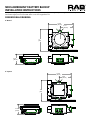
ROUGHIN MOUNTING
1. Nailer bars are provided for use with wood joist
installations. Insert through Nailer Bar Slots in
Buttery Brackets and secure accordingly. C-Channels
are optionally available, consult factory. Consult local
building codes for nal support of xture.
2. Remove appropriate Knock out on Junction box. Press
Clip to remove the Junction Box Cover.
3. Feed the supply wires through Knock out hole and
connect to the driver. Re-install Junction Box Cover. See
wiring section for details.
4. The xture can be adjusted to dierent heights above
the ceiling surface. For height adjustment, loosen the
Wing Nut and slide the Buttery Bracket. If necessary
remove the Wing Nut and insert in screw in dierent
hole provided on the Buttery Bracket. (Fig: 2)
5. Adjust both the Buttery Brackets such that the frame
of Rough-In Section is ush with the nished ceiling
surface. Tighten the Wing nuts.
Rough-in Section
(Bottom of the Rough-in
Section to be ush with
nished ceiling)
Buttery Brackets
Male Connector
Knock Out
Clip
Junction Box
Cover
Fig. 1
Buttery
Bracket
Wing Nut
Fig. 2
Nailer Bar Slot
TRIM MODULE MOUNTING
1. Pull Male Connector conduit through frame opening.
Raise Trim Module towards opening and connect to
Female Connector conduit as shown in Fig. 3.
2. Press Torsion Springs inward and slide Trim Module
info frame opening. Release both springs into opening
together. Trim Ring should be ush to ceiling.
3. For the Wallwash Model, orient the xture such that the
reector is in correct orientation. Look for ‘Towards the
Wall’ label on the xture.
Ceiling
Male Connector
Female Connector
Rough-in Section
Trim Module
Torsion Spring
Trim Ring
Fig. 3

NDIC6 EMERGENCY BATTERY BACKUP
INSTALLATION INSTRUCTIONS
Thank you for buying RAB lighting xtures. Our goal is to design the best quality products to get the job done right. We’d like to hear your comments.
Call the Marketing Department at 888-RAB-1000 or email: marketing@rabweb.com
Easy Installation & Product Help
Tech Help Line
Call our experts 888 RAB-1000
©2014 RAB LIGHTING Inc.
No
rthvale, New Jersey 07647 USA
rabweb.com
Visit our website for product info
email
Answered promptly sales@rabweb.com
NDIC4 EM IN 1115
Note: These instructions do not cover all details or variations in
equipment nor do they provide for every possible situation during installation, operation or maintenance. RAB cannot troubleshoot Lutron systems
and have provided only basic information. See www.lutron.com for complete instructions and functional compatibility of Lutron Drivers with Lutron or
other Control systems/dimmers.
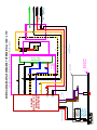
WIRING
CAUTION: THIS IS AN EMERGENCY BATTERY BACKUP
FIXTURE. Voltage could be present in Battery. To prevent
high voltage from being present on output leads, inverter
connector must be open. Do not join inverter connector
until installation is complete and AC power is supplied to
the emergency ballast.
NOTE: Make sure that the necessary branch circuit wiring is
available. An unswitched AC source of power is required. The
emergency ballast must be fed from the same branch circuit
as the AC ballast.
Do not use any supply voltage other than those specied
below.
NDIC6R/E2 or NDIC6S/E2 120V-277V, 50/60Hz
1. Connect the UNSWITCHED black xture lead to the HOT
supply lead.
2. Connect red and black lead together, if not using a
switching method.
3. If switching, connect SWITCHED red lead to a switch.
4. Connect the COMMON xture lead to the COMMON
supply lead.
5. For Lutron system, follow manufacturer’s instructions.
5. Connect the GROUND wire from xture to supply ground.
Do NOT connect the GROUND of the dimming xture to
the output.
6. All unused leads must be capped and insulated.
7. After installation is complete, supply AC power to the
emergency ballast and join the inverter connector.
9. At this point, power should be connected to both the
AC ballast and the emergency ballast, and the Charging
Indicator Light should illuminate indicating the battery is
charging.
10. A short-term discharge test may be conducted after the
emergency ballast has been charging for one hour. Charge
for 24 hours before conducting a long-term discharge test.
Refer to OPERATION.
MAINTENANCE
Although no routine maintenance is required to keep
the emergency ballast functional, it should be checked
periodically to ensure that it is working. The following
schedule is recommended:
1. Visually inspect the charging indicator light monthly. It
should be illuminated.
2. Test the emergency operation of the xture at 30-day
intervals for a minimum of 30 seconds.
3. Conduct a 90-minute discharge test once a year. Fixture
would operate at reduced illumination for a minimum of
90 minutes.
To reduce the risk of electric shock, disconnect both normal and emergency power supplies and converter connector of the emergency ballast before
servicing. Do not attempt to service the emergency ballast. The use of accessory equipment may cause an unsafe condition. Do not use this product for
other than intended use. Refer any servicing indicated by these checks to a Qualied Service Personnel.
CLEANING
CAUTION: Be sure xture temperature is cool enough to
touch. Do not clean or maintain while xture is energized.
1. Do not open xture to clean the LEDs. Do not touch the
LEDs.
2. Do not touch reector, lens, or trim cone.
3. Do not clean any xture surface with wood base cleaning
material such as paper towels or tissues. Only use micro
ber cleaning cloth.
TROUBLESHOOTING
1. Check that the line voltage at the xture is correct. Refer
to wiring directions.
2. Is the xture grounded properly?
3. For questions on compatibility of dimmers purchased
separately refer to www.rabweb.com
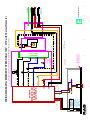
4. If the LED is blinking the xture may be overheating.
Remove the Trim assembly and if the xture is labeled
‘BLINKING LIGHT OF THIS THERMALLY PROTECTED
LUMINAIRE MAY INDICATE OVERHEATING’ allow the
xture to cool down. Determine cause of overheating
and remove. Fixtures with this label have a thermal
protector that turns xture o above a certain
temperature. It will automatically restart when cool.

NDIC6 EMERGENCY BATTERY BACKUP
INSTALLATION INSTRUCTIONS
Thank you for buying RAB lighting xtures. Our goal is to design the best quality products to get the job done right. We’d like to hear your comments.
Call the Marketing Department at 888-RAB-1000 or email: marketing@rabweb.com
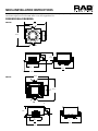
15.452
[392,48]
8.110
[205,99]
6.125
[155,56]
13
[330]
DIMENSIONAL DRAWING
6” Round
6” Square
15.362
[390,19]
8.065
[204,85]
13
[330]
6.125
[155,56]

WIRING DIAGRAM for EMERGENCY OPERATION at 120V - 277V
Emergency Ballast and AC Ballast must be fed from the same circuit
+
-
BODINE
BSL17C-C2
EMERGENCY
LED DRIVER
INVERTER
CONNECTOR:
CONNECT ONLY AFTER
AC SUPPLY POWER IS
CONNECTED
CUSTOMER SHOULD
CONNECT ONLY
AFTER FINISHING
WIRING TO AC
POWER. BATTERY
COULD HAVE
CHARGE & SHOCK.
RAB LABEL - ADD
LED DRIVER
120V - 277V
COMMON
GROUND
SWITCH PLATE WITH
INTEGRAL TEST
SWITCH (INCLUDED)
SWITCH BOX
(BY OTHERS)
ELECTRONIC
BLOCK
PROTECTOR
JUNCTION BOX
JUNCTION
BOX
LED TRIM MODULE
RED
WHITE
BROWN
BROWN
VIOLET
VIOLET
ORANGE
- BLACK
STRIPE
WHITE
- RED
STRIPE
YELLOW
YELLOW - BLACK STRIPE
BLUE
WHITE - BLACK STRIPE
WHITE
BLACK
WHITE
BLUE -
OR
BLACK -
RED +
RED
RED
YELLOW
WHITE
YELLOW - BLACK STRIPE
BLACK
2' Flex Conduit Whip
8" Flex Conduit Whip
BLACK
UNSWITCHED
CONNECT TO
MAIN POWER
RAB LABEL -
ADD
BLACK
SWITCHED
IF NOT SWITCHED, THEN
CAP TOGETHER
RAB LABEL -
ADD
BLACK
BLUE
Easy Installation & Product Help
Tech Help Line
Call our experts 888 RAB-1000
©2012 RAB LIGHTING Inc.
Northvale, New Jersey 07647 USA
rabweb.com
Visit our website for product info
email
Answered promptly sales@rabweb.com
NDIC46 EM IN 1215

WIRING DIAGRAM for EMERGENCY OPERATION at 120V - 277V with Thermal Protector
Emergency Ballast and AC Ballast must be fed from the same circuit
+
-
BODINE
BSL17C-C2
EMERGENCY
LED DRIVER
INVERTER
CONNECTOR:
CONNECT ONLY AFTER
AC SUPPLY POWER IS
CONNECTED
CUSTOMER SHOULD
CONNECT ONLY
AFTER FINISHING
WIRING TO AC
POWER. BATTERY
COULD HAVE
CHARGE & SHOCK.
RAB LABEL - ADD
LED DRIVER
120V - 277V
COMMON
GROUND
SWITCH PLATE WITH
INTEGRAL TEST
SWITCH (INCLUDED)
SWITCH BOX
(BY OTHERS)
ELECTRONIC
BLOCK
PROTECTOR
JUNCTION BOX
JUNCTION
BOX
LED TRIM MODULE
RED
WHITE
BROWN
BROWN
VIOLET
VIOLET
ORANGE
- BLACK
STRIPE
WHITE
- RED
STRIPE
YELLOW
YELLOW - BLACK STRIPE
BLUE
WHITE - BLACK STRIPE
WHITE
BLACK
WHITE
BLUE -
OR
BLACK -
RED +
RED
RED
YELLOW
WHITE
YELLOW - BLACK STRIPE
BLACK
TP
TP
Thermal Protector
BLACKBLACK
2' Flex Conduit Whip
8" Flex Conduit Whip
BLACK
UNSWITCHED
CONNECT TO
MAIN POWER
RAB LABEL -
ADD
BLACK
SWITCHED
IF NOT SWITCHED, THEN
CAP TOGETHER
RAB LABEL -
ADD
BLACK
BLUE
Easy Installation & Product Help
Tech Help Line
Call our experts 888 RAB-1000
©2012 RAB LIGHTING Inc.
Northvale, New Jersey 07647 USA
rabweb.com
Visit our website for product info
email
Answered promptly sales@rabweb.com
NDIC6 EM IN 1215
-
 1
1
-
 2
2
-
 3
3
-
 4
4
-
 5
5
-
 6
6
-
 7
7
-
 8
8
-
 9
9
-
 10
10
-
 11
11
-
 12
12
-
 13
13
-
 14
14


RAB Lighting ND6S26D/E2 Operating instructions
- Type
- Operating instructions
Ask a question and I''ll find the answer in the document
Finding information in a document is now easier with AI
Related papers
-
RAB Lighting D8TRIMS Operating instructions
-
RAB Lighting NDLED4RD-80YNHC-M-S Operating instructions
-
RAB Lighting NDLED4SD-WYN-W-B Operating instructions
-
RAB Lighting RDLED4R12D-50YYHC-M-W Operating instructions
-
RAB Lighting ND4S12D Operating instructions
-
-
-
-
RAB Lighting LALED78W Operating instructions
-
RAB Lighting SLIM18YW/PC Operating instructions
Other documents
-
Designers Choice Collection VF3400-1L-SN Operating instructions
-
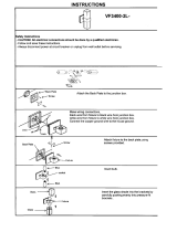 Designers Choice Collection VF3400-2L-CH Operating instructions
-
Lightolier 3 3/4” Incandescent IC Insulated Ceiling Frame-In Kit Install Instructions
-
Wayfair Canada LED Flush Mount Light User manual
-
 Generation Lighting 14916RD Installation guide
-
 BARRON TLED804 Series Die-cast Globe Vaportight Installation guide
-
Chloride ZIS25W Install Instructions
-
 BARRON TLED111P Series Half Round Wall Sconce Installation guide
-
United Nursery 26769 User manual
-
 George Kovacs P4344-084 User manual


