Page is loading ...

1
Chapter 1 Introduction
www.d.com
A54610952
VP101-BT
Fanless In-Vehicle Panel PC System with Touchscreen
User’s Manual

2
Chapter 1 Introduction
www.d.com
Copyright
This publication contains information that is protected by copyright. No part of it may be re-
produced in any form or by any means or used to make any transformation/adaptation without
the prior written permission from the copyright holders.
This publication is provided for informational purposes only. The manufacturer makes no
representations or warranties with respect to the contents or use of this manual and specifi-
cally disclaims any express or implied warranties of merchantability or fitness for any particular
purpose. The user will assume the entire risk of the use or the results of the use of this docu-
ment. Further, the manufacturer reserves the right to revise this publication and make changes
to its contents at any time, without obligation to notify any person or entity of such revisions
or changes.
Changes after the publication’s first release will be based on the product’s revision. The website
will always provide the most updated information.
© 2019. All Rights Reserved.
Trademarks
Product names or trademarks appearing in this manual are for identification purpose only and
are the properties of the respective owners.
FCC and DOC Statement on Class A
This equipment has been tested and found to comply with the limits for a Class A digital
device, pursuant to Part 15 of the FCC rules. These limits are designed to provide reason-
able protection against harmful interference when the equipment is operated in a residential
installation. This equipment generates, uses and can radiate radio frequency energy and, if not
installed and used in accordance with the instruction manual, may cause harmful interference
to radio communications. However, there is no guarantee that interference will not occur in a
particular installation. If this equipment does cause harmful interference to radio or television
reception, which can be determined by turning the equipment off and on, the user is encour-
aged to try to correct the interference by one or more of the following measures:
• Reorient or relocate the receiving antenna.
• Increase the separation between the equipment and the receiver.
• Connect the equipment into an outlet on a circuit different from that to which the receiver
is connected.
• Consult the dealer or an experienced radio TV technician for help.
Notice:
1. The changes or modifications not expressly approved by the party responsible for compli-
ance could void the user’s authority to operate the equipment.
2. Shielded interface cables must be used in order to comply with the emission limits.

3
Chapter 1 Introduction
www.d.com
Table of Contents
Copyright ............................................................................2
Trademarks .........................................................................2
FCC and DOC Statement on Class A ....................................2
Warranty ...........................................................................4
Static Electricity Precautions ................................................4
Safety Measures..................................................................4
Safety Precautions ..............................................................5
About the Package ..............................................................5
Chapter 1 - Introduction ......................................................6
Overview .................................................................................6
Key Features ...........................................................................6
Specifications ...........................................................................7
Getting to Know the VP101-BT ................................................ 8
Mechanical Dimensions ............................................................9
Chapter 2 - Getting Started ...............................................10
Chapter 3 - Installing Devices ............................................ 11
Removing the Chassis Cover ...................................................11
Chapter 4 - Jumper Settings .............................................. 14
Chapter 5 - Ports and Connectors ......................................18
Chapter 6 - Mounting Options ...........................................25
Wall Mount ............................................................................ 25
Panel Mount ..........................................................................26
Chapter 7 - BIOS Setup ....................................................28
Chapter 8 - Supported Software ........................................40

4
Chapter 1 Introduction
www.d.com
About this Manual
An electronic file of this manual can be obtained from the DFI website at www.dfi.com.
To download the user’s manual from our website, please go to “Support” > “Download Center.”
On the Download Center page, select your product or type the model name and click “Search”
to find all technical documents including the user’s manual for a specific product.
Warranty
1. Warranty does not cover damages or failures that arised from misuse of the product,
inability to use the product, unauthorized replacement or alteration of components and
product specifications.
2. The warranty is void if the product has been subjected to physical abuse, improper instal-
lation, modification, accidents or unauthorized repair of the product.
3. Unless otherwise instructed in this user’s manual, the user may not, under any circum-
stances, attempt to perform service, adjustments or repairs on the product, whether in or
out of warranty. It must be returned to the purchase point, factory or authorized service
agency for all such work.
4. We will not be liable for any indirect, special, incidental or consequential damages to the
product that has been modified or altered.
Static Electricity Precautions
It is quite easy to inadvertently damage your PC, system board, components or devices even
before installing them in your system unit. Static electrical discharge can damage computer
components without causing any signs of physical damage. You must take extra care in han-
dling them to ensure against electrostatic build-up.
1. To prevent electrostatic build-up, leave the system board in its anti-static bag until you are
ready to install it.
2. Wear an antistatic wrist strap.
3. Do all preparation work on a static-free surface.
4. Hold the device only by its edges. Be careful not to touch any of the components, contacts
or connections.
5. Avoid touching the pins or contacts on all modules and connectors. Hold modules or con-
nectors by their ends.
Safety Measures
To avoid damages to the system:
• Use the correct AC input voltage range.
To reduce the risk of electric shock:
• Unplug the power cord before removing the system chassis cover for installation or servic-
ing. After installation or servicing, cover the system chassis before plugging the power cord.
Battery:
• Danger of explosion if battery incorrectly replaced.
• Replace only with the same or equivalent type recommend by the manufacturer.
• Dispose of used batteries according to local ordinance.
Important:
Electrostatic discharge (ESD) can damage your processor, disk drive and other com-
ponents. Perform the upgrade instruction procedures described at an ESD worksta-
tion only. If such a station is not available, you can provide some ESD protection by
wearing an antistatic wrist strap and attaching it to a metal part of the system chas-
sis. If a wrist strap is unavailable, establish and maintain contact with the system
chassis throughout any procedures requiring ESD protection.

5
Chapter 1 Introduction
www.d.com
About the Package
The package contains the following items. If any of these items are missing or damaged,
please contact your dealer or sales representative for assistance.
• 1 VP101-BT Touch Panel PC
• One
sheet of Poron Foam
• 1 Chassis Panel Mount Bracket
• 1 Quick Installation Guide
Optional Items
• Wall Mount kit
• Panel Mount kit
• Power Cord
The board and accessories in the package may not come similar to the information listed
above. This may differ in accordance to the sales region or models in which it was sold. For
more information about the standard package in your region, please contact your dealer or
sales representative.
Safety Precautions
• Use the correct DC input voltage range.
• Unplug the power cord before removing the system chassis cover for installation or servic-
ing. After installation or servicing, cover the system chassis before plugging the power cord.
• Danger of explosion if battery incorrectly replaced.
• Replace only with the same or equivalent type recommend by the manufacturer.
• Dispose of used batteries according to local ordinance.
• Keep this system away from humidity.
• Place the system on a stable surface. Dropping it or letting it fall may cause damage.
• The openings on the system are for air ventilation to protect the system from overheating.
DO NOT COVER THE OPENINGS.
• Place the power cord in such a way that it will not be stepped on. Do not place anything on
top of the power cord. Use a power cord that has been approved for use with the system
and that it matches the voltage and current marked on the system’s electrical range label.
• If the system will not be used for a long time, disconnect it from the power source to avoid
damage by transient overvoltage.
• If one of the following occurs, consult a service personnel:
- The power cord or plug is damaged.
- Liquid has penetrated the system.
- The system has been exposed to moisture.
- The system is not working properly.
- The system dropped or is damaged.
- The system has obvious signs of breakage.
• The unit uses a three-wire ground cable which is equipped with a third pin to ground the
unit and prevent electric shock. Do not defeat the purpose of this pin. If your outlet does
not support this kind of plug, contact your electrician to replace the outlet.
• Disconnect the system from the DC outlet before cleaning. Use a damp cloth. Do not use
liquid or spray detergents for cleaning.

6
Chapter 1 Introduction
www.d.com
Chapter 1 - Introduction
Chapter 1
Overview
VP101-BT
Top View
Key Features
Model Name VP101-BT
Processor Intel Atom
®
Processor E3800 Series
LAN Two LAN ports
COM Five serial ports
Display Capacitive touchscreen
One VGA
One HDMI
USB One USB 3.0 port and three USB 2.0 ports
Audio Line-out and Microphone ports
Power In-vehicle power management features
Side View
Bottom View

7
Chapter 1 Introduction
www.d.com
Specifications
Chapter 1
Note:
*The mounting kit is optional and not supported in standard model. Please con-
tact your sales representative for more information.
Vibration OP: Random, 1Grms @ 5~500Hz, 30min
Non-OP: Sweep sine, 3Grms @ 10~500Hz, 30min
Shock OP: Half-sine, 3G @ 11ms
Non-OP: Half-sine, 5G @ 11ms
Construction
• Aluminum Front Bezel
• IP65 Front Panel Protection
Mounting
• Panel/VESA
mount
- Mounting brackets and screws
*
Dimensions • 294mm x 193mm x 65mm (W x H x D)
Weight • 1.7 Kg
OS Support
• Windows 7 (32bit/64bit)
• Windows 10 IoT Enterprise (32bit/64bit)
• Ubuntu 16.04 (64-bit)
Certications
CE, FCC Class A, E-Mark (E13)
Processor
System
Intel Atom
®
Processor E3800 Series, BGA 1170
Intel Atom
®
E3845, Quad Core, 2M Cache, 1.91GHz, 10W
Intel Atom
®
E3825, Dual Core, 1M Cache, 1.33GHz, 6W
Memory • 2GB/4GB DDR3L-1333MHz onboard memory with ECC support
Touch Screen &
Graphics
Touchscreen
• 10.1” 1280x800 TFT LCD Panel with capacitive touchscreen
• Brightness: 500 cd/m
2
• Contrast: 800:1
• Backlight Lifetime: 50,000 hours
Graphics
• Controller: Intel
®
HD Graphics
• Display interfaces:
1 VGA port (24-bit, resolution up to 2560x1600 @ 60Hz)
1 HDMI port (resolution up to 1920x1080 @ 60Hz)
Storage/
Expansion
• 1 x 2.5" SATA 2.0 Drive Bay
• Onboard eMMC Storage:
4GB/8GB/16GB/32GB (available upon request)
• Expansion Slots:
1 x Full-size Mini PCIe (PCIe/USB/3G/GPRS/CAN-Bus) plus a SIM card slot
• 1 x Full-size Mini PCIe (SATA)
• 1 x Half-size Mini PCIe (PCIe/USB/LPC)
• 1 x microSD (available upon request)
Ethernet 2 x Intel
®
I210AT PCIe (10/100/1000Mbps)
I/O Ports and
LED Indicators
• Top Panel
- 3 x RS232/422/485 (DB9; one supports 8-bit DIO or CAN-Bus)
- 1 x USB 3.0 (type A)
- 1 x HDMI
- 1 x power button
- 1 x reset button
- 2 x Wi-Fi module antenna hole
• Bottom Panel
- 1 x 3-pole power connector (terminal block)
- 2 x GbE (RJ-45)
- 2 x RS232/422/485 (DB9; one supports only RS232)
- 3 x USB 2.0 (type A)
- 1 x VGA
- 1 x Line-out and Mic-in
- 1 x Wi-Fi module antenna hole
Power • Wide Range 9~36V DC-in (3-pin terminal block; VCC/ACC/GND)
In-Vehicle power management includes ignition On/Off and system on/off
delay time control
Environment • Temperature
- Operating: -20
o
C ~ 60
o
C
- Storage: -30
o
C ~ 80
o
C
- Relative Humidity: 5 to 85% RH (non-condensing)

8
Chapter 1 Introduction
www.d.com
Power LED (Green)
This button only indicates power-on or power-off status. Note that this button cannot
be used to power on or off the system; please power on or off the system via car
ignition.
Status LED (Blue)
Indicates system status.
Reset Switch
Press to restart the system without going through a full shutdown and boot cycle.
HDMI Port
Connects to the HDMI port of a display.
USB 3.0 Port
Connects USB 3.0 devices as well as devices from previous versions such as USB 2.0
or USB 1.1.
COM Ports
COM 1, COM 2 and COM 4 can be an RS232, RS422 or RS485 port. COM 4 can be
used as an 8-bit Digital I/O, a serial or CANbus port via jumper selection.
Wireless Antenna Holes
Reserved for installing wireless antennas.
Getting to Know the VP101-BT
Chapter 1
Top View
Bottom View
Power Connector
Connects a car battery for power supply.
LAN Ports
Connect a network device or a LAN cable for network connectivity.
USB 2.0 Ports
Connect USB 2.0 or 1.1 devices.
Line-out
Connects a speaker.
Mic-in
Connects a microphone.
COM Ports
Connect serial devices. COM 3 can be an RS232, RS422 or RS485 port; COM 5 can
only be an RS232 port.
VGA
Connects the VGA port of a display device.
Status LED
Suspend Mode S0 S1-S3 (sleep) S4, S5
LED Behavior
Off Blinking Off
Antenna
hole
COM 2/1
(RS232/RS422/RS485)
HDMI
COM 4 (RS232/422/485) / 8-bit DIO
CANbus
USB 3.0
Reset switch/
Status LED
VGA
USB 2.0
LAN 2
Line-out
LAN 1
MIC-in
VCC/ACC/GND
(Connects to car battery)
COM 3
(RS232/RS422/RS485)
COM 5
(RS232)
Power LED

9
Chapter 1 Introduction
www.d.com
Motherboard Dimensions
Chapter 1
Mechanical Dimensions
293.51
193
166.60
118
65
Bottom View
Top View
Right View
Left View
Front View
0
0
6.1
14.9
28.4
70.4
106.41
142.4
160
165
5
160
147.4
108.4
21.81
38.31
51.4
59.9
68.4
90.4
144.9
5
90.4
144.9
21.8
9.65
97
107
115
11.8
19.8
103.35
99.26
102.93
113.4
11.45
1.6
105.85
Standard

10
Chapter 2 Getting Started
Chapter 2 - Getting Started
Chapter 2
Preparing the System
Before you start using the system, you need the following items:
• AC power adapter
• DVD-ROM drive (for installing software/drivers)
• Screwdriver
Installing Devices
The following devices can be installed in the system.
• Mini PCIe/mSATA cards
Configuring the BIOS
To get you started, you may need to change configurations such as the date, time and the
type of hard disk drive.
1. Power on the system.
2. After the memory test, the message “Press DEL to run setup” will appear on the screen.
Press the Delete key to enter the BIOS setup utility.
Installing the Operating System
Most operating system software can be installed using a DVD (and DVD burner) or bootable
USB drive.
Please refer to your operating system manual for instructions on installing an operating system.
Installing the Drivers
The system requires you to install drivers for some devices to operate properly. Refer to the
Supported Software chapter for instructions on installing the drivers.

www.d.com
11
Chapter 3
Chapter 3 Installing Devices
Chapter 3 - Installing Devices
Removing the Chassis Cover
1. Make sure the system and all other peripheral devices connected to it have been powered
off.
2. Disconnect all power cords and cables.
3. The 12 mounting screws on the bottom and two sides of the system are used to secure the
cover to the chassis. Remove these screws and then put them in a safe place for later use.
4. After removing the mounting screws, lift the bottom side of the chassis cover to open the
system. The Mini PCIe and the micro SD slots will be readily accessible.
5. The Mini PCIe and the micro SD (optional) slots are readily accessible after removing the
chassis cover.
Installing a SATA Drive
The system can accomondate one SATA drive. Please use the following procedure to install a
SATA drive into the system.
1. The SATA data and power connectors are on the system board beneath the power board.
Please remove the power board rst to take out the SATA HDD bracket.
2. Align the mounting holes of the SATA drive with the mounting holes on the SATA HDD
bracket and use the provided mounting screws to attach the SATA drive to the bracket.
Please observe the following guidelines and follow the procedure to open the system.
Chassis screw
Mini PCIe slots
micro SD
Power board
Power board
Mounting screws
SATA HDD bracket
Mounting screws
SATA
Mounting screws

www.d.com
12
Chapter 3
Chapter 3 Installing Devices
3. Connect one end of the SATA cable to the SATA power and data connectors on the SATA
drive and the other end of the SATA cable to the SATA power and data connectors on the
system board.
4. Align the mounting holes of the SATA HDD bracket with the mounting holes on the
system board and use the provided mounting screws to secure the HDD bracket in place.
Installing a Mini PCIe Card
The system board is equipped with 3 Mini PCIe slots: two full-size and one half-size slots. Here
we will demonstrate the installation of a half-size Mini PCIe card (
PCIe/USB/LPC signals
) for WiFi
connection and a full-size slot for
CANbus communication (PCIe/USB/3G/GPRS/CANbus signals)
.
Installing a Wi-Fi card in the half-size Mini PCIe slot
1. Grasp the Mini PCIe card by its edges and align the notch in the connector of the card with
the notch in the connector on the system board.
2. Push the Mini PCIe card down and use the provided mounting screws to secure the card on
the system board.
SATA connectors
on the board
SATA connectors
SATA HDD bracket
mounting screw
SATA HDD bracket
mounting screw
Mounting screw

www.d.com
13
Chapter 3
Chapter 3 Installing Devices
To install a CANbus card, connect the cable between the card the pin headers (JP21 and JP22),
then you can use COM 4 as a CANbus port. For pin assignments for COM 4, refer to Chapter 5 ̶
Ports and Connectors. To switch signals for COM 4, refer to Chapter 4 ̶ Jumper Settings.
Installing a CANbus card in the Mini PCIe slot
Note:
The system also has one additional full-size Mini PCIe slot that provides mSATA
(SATA signals) interface.
COM 4/ 8-bit DIO/CANbus
CANbus pin headers
Mounting screw
CANbus card

14
Chapter 4 Jumper Settings
Chapter 4
Chapter 4 - Jumper Settings
Clear CMOS Data
LAN 1
LAN 2
10
9
COM 5
DDR3L
DDR3L
DDR3L
DDR3L
Mini PCIe with SIM
COM 4
1210
31
JP22
1
1
1
(JP20)
(JP18)
(JP17)
(JP21)
1 3
1210
COM 2
USB 0
USB 3.0
HDMI
Reset
Power
DC-in
USB 2
USB 7
USB 1
USB 6
COM 3
1
Battery
Buzzer
1
Clear CMOS
Data (JP24)
SPI
Flash
BIOS
eMMC
(optional)
iTE
IT8528E
Mini PCIe with LPC mSATA
MicroSD
(optional)
1
USB 0
Power
Select
(JP5)
1
1 1
USB 1-2
Power Select (JP6)
USB 5-7 Power
Select (JP7)
(JP25)
USB 2.0
(JP17)
(JP20)
COM 4/DIO Select
(JP22, JP21)
Digital I/O 0-3 Output State
Digital I/O Power Select
Auto
Power-on
Select
(JP18)
Digital I/O 4-7 Output State
VGA
DC-in
from
Power board
14
SATA 2.0
1
SATA 0
SATA Power
Mic-in
Line-out
COM 1
JP24
2-3 On:
Clear CMOS Data
1-2 On:
Normal (default)
1
3
2
1
3
2
If you encounter the following situations, you can reconfigure the system with the default val-
ues stored in the ROM BIOS.
a) CMOS data becomes corrupted.
b) You forgot the supervisor or user password.
To load the default values stored in the ROM BIOS, please follow the steps below.
1. Power-off the system and unplug the power cord.
2. Set the jumper pins 2 and 3 to On. Wait for a few seconds and set the jumper back to its
default setting, pins 1 and 2 On.
3. Now plug the power cord and power-on the system.
Auto Power-on Select
JP25 is used to select the method of powering on the system. If you want the system to pow-
er on whenever AC power comes in, set the jumper pins 2 and 3 to “On.” If you want to use
the power button, set pins 1 and 2 to “On.”
When using the “Power-On” feature to power the system back on after a power failure occurs,
the system may not power on if the power loss is resumed within 5 seconds (power flicker).
1-2 On:
Power-on via power button
2-3 On:
Power-on via AC power
(default)
1 32
1 32
LAN 1
LAN 2
10
9
COM 5
DDR3L
DDR3L
DDR3L
DDR3L
Mini PCIe with SIM
COM 4
1210
31
JP22
1
1
1
(JP20)
(JP18)
(JP17)
(JP21)
1 3
1210
COM 2
USB 0
USB 3.0
HDMI
Reset
Power
DC-in
USB 2
USB 7
USB 1
USB 6
COM 3
1
Battery
Buzzer
1
Clear CMOS
Data (JP24)
SPI
Flash
BIOS
eMMC
(optional)
iTE
IT8528E
Mini PCIe with LPC mSATA
MicroSD
(optional)
1
USB 0
Power
Select
(JP5)
1
1 1
USB 1-2
Power Select (JP6)
USB 5-7 Power
Select (JP7)
(JP25)
USB 2.0
(JP17)
(JP20)
COM 4/DIO Select
(JP22, JP21)
Digital I/O 0-3 Output State
Digital I/O Power Select
Auto
Power-on
Select
(JP18)
Digital I/O 4-7 Output State
VGA
DC-in
from
Power board
14
SATA 2.0
1
SATA 0
SATA Power
Mic-in
Line-out
COM 1
JP25

15
Chapter 4 Jumper Settings
Chapter 4
JP5, JP6 and JP7 are used to select the power of the USB ports. Selecting +5V_standby will
allow you to use USB devices to wake up the system.
Important:
If you are using the Wake-On-USB Keyboard/Mouse function for 2 USB ports, the
+5V_standby power source of your power supply must support ≥1.5A. For 3 or more
USB ports, the +5V_standby power source of your power supply must support ≥2A.
USB Power Select
1 32
1-2 On:
+5V_standby
(default)
1 32
2-3 On: +5V
USB 0
(JP5)
USB 6, 7
(JP7)
LAN 1
LAN 2
10
9
COM 5
DDR3L
DDR3L
DDR3L
DDR3L
Mini PCIe with SIM
COM 4
1210
31
JP22
1
1
1
(JP20)
(JP18)
(JP17)
(JP21)
1 3
1210
COM 2
USB 0
USB 3.0
HDMI
Reset
Power
DC-in
USB 2
USB 7
USB 1
USB 6
COM 3
1
Battery
Buzzer
1
Clear CMOS
Data (JP24)
SPI
Flash
BIOS
eMMC
(optional)
iTE
IT8528E
Mini PCIe with LPC mSATA
MicroSD
(optional)
1
USB 0
Power
Select
(JP5)
1
1 1
USB 1-2
Power Select (JP6)
USB 5-7 Power
Select (JP7)
(JP25)
USB 2.0
(JP17)
(JP20)
COM 4/DIO Select
(JP22, JP21)
Digital I/O 0-3 Output State
Digital I/O Power Select
Auto
Power-on
Select
(JP18)
Digital I/O 4-7 Output State
VGA
DC-in
from
Power board
14
SATA 2.0
1
SATA 0
SATA Power
Mic-in
Line-out
COM 1
USB 1, 2
(JP6)
1
3
2
1-2 On:
+5V_standby
(default)
1
3
2
2-3 On: +5V
1
3
2
1-2 On:
+5V_standby
(default)
1
3
2
2-3 On: +5V
Digital I/O Power Select
1 32
1 32
1-2 On:
+5V_standby
2-3 On: +5V
(default)
LAN 1
LAN 2
10
9
COM 5
DDR3L
DDR3L
DDR3L
DDR3L
Mini PCIe with SIM
COM 4
1210
31
JP22
1
1
1
(JP20)
(JP18)
(JP17)
(JP21)
1 3
1210
COM 2
USB 0
USB 3.0
HDMI
Reset
Power
DC-in
USB 2
USB 7
USB 1
USB 6
COM 3
1
Battery
Buzzer
1
Clear CMOS
Data (JP24)
SPI
Flash
BIOS
eMMC
(optional)
iTE
IT8528E
Mini PCIe with LPC mSATA
MicroSD
(optional)
1
USB 0
Power
Select
(JP5)
1
1 1
USB 1-2
Power Select (JP6)
USB 5-7 Power
Select (JP7)
(JP25)
USB 2.0
(JP17)
(JP20)
COM 4/DIO Select
(JP22, JP21)
Digital I/O 0-3 Output State
Digital I/O Power Select
Auto
Power-on
Select
(JP18)
Digital I/O 4-7 Output State
VGA
DC-in
from
Power board
14
SATA 2.0
1
SATA 0
SATA Power
Mic-in
Line-out
COM 1
JP17
JP17 is used to select the power of the DIO (Digital I/O) signal.

16
Chapter 4 Jumper Settings
Chapter 4
Digital I/O Output State
LAN 1
LAN 2
10
9
COM 5
DDR3L
DDR3L
DDR3L
DDR3L
Mini PCIe with SIM
COM 4
1210
31
JP22
1
1
1
(JP20)
(JP18)
(JP17)
(JP21)
1 3
1210
COM 2
USB 0
USB 3.0
HDMI
Reset
Power
DC-in
USB 2
USB 7
USB 1
USB 6
COM 3
1
Battery
Buzzer
1
Clear CMOS
Data (JP24)
SPI
Flash
BIOS
eMMC
(optional)
iTE
IT8528E
Mini PCIe with LPC mSATA
MicroSD
(optional)
1
USB 0
Power
Select
(JP5)
1
1 1
USB 1-2
Power Select (JP6)
USB 5-7 Power
Select (JP7)
(JP25)
USB 2.0
(JP17)
(JP20)
COM 4/DIO Select
(JP22, JP21)
Digital I/O 0-3 Output State
Digital I/O Power Select
Auto
Power-on
Select
(JP18)
Digital I/O 4-7 Output State
VGA
DC-in
from
Power board
14
SATA 2.0
1
SATA 0
SATA Power
Mic-in
Line-out
COM 1
JP20 (DIO 0-3)
JP18 (DIO 4-7)
1 32
1-2 On:
GND (default)
1 32
2-3 On:
+5V or +5V_standby
COM 4/DIO/CANbus Select
The system board uses JP21 and JP22 to select among serial port COM 4, 8-bit DIO or CAN-
bus on the front panel. For more information on installing a CANbus card, please refer to
Chapter 3
̶
Installing Devices
.
Note:
You cannot use COM 4, DIO and CANbus at the same time. Please set up
JP21 and JP22 together.
LAN 1
LAN 2
10
9
COM 5
DDR3L
DDR3L
DDR3L
DDR3L
Mini PCIe with SIM
COM 4
1210
31
JP22
1
1
1
(JP20)
(JP18)
(JP17)
(JP21)
1 3
1210
COM 2
USB 0
USB 3.0
HDMI
Reset
Power
DC-in
USB 2
USB 7
USB 1
USB 6
COM 3
1
Battery
Buzzer
1
Clear CMOS
Data (JP24)
SPI
Flash
BIOS
eMMC
(optional)
iTE
IT8528E
Mini PCIe with LPC mSATA
MicroSD
(optional)
1
USB 0
Power
Select
(JP5)
1
1 1
USB 1-2
Power Select (JP6)
USB 5-7 Power
Select (JP7)
(JP25)
USB 2.0
(JP17)
(JP20)
COM 4/DIO Select
(JP22, JP21)
Digital I/O 0-3 Output State
Digital I/O Power Select
Auto
Power-on
Select
(JP18)
Digital I/O 4-7 Output State
VGA
DC-in
from
Power board
14
SATA 2.0
1
SATA 0
SATA Power
Mic-in
Line-out
COM 1
JP22
JP21
1-2, 4-5, 7-8, 10-11 On:
COM 4 (default)
7
9
10 12
4 6
1
3
2-3, 5-6, 8-9, 11-12 On:
DIO
7
9
1
3
10
12
4
6
No jumper: CANbus
7
9
10 12
4 6
1
3
JP20 (DIO pin 0-3) and JP18 (DIO pin 4-7) are used to select the state of DIO output: pull-
high or pull-low. When the pull-high state is selected, the level of the DIO signal will be the
same as the JP17’s setting.

17
Chapter 4 Jumper Settings
Chapter 4
SW1-2: System-on delay enable/disable
On (Default) Enable (delay time setting adjust-
able by SW1-4 and 1-5 as shown
below)
Off Disable (System-on delay = 3 sec)
SW1-4 and 1-5: System-on delay time setting
4 5 Time
On On 10 sec (default)
Off On 30 sec
On Off 1 min
Off Off 5 min
SW1-3: System-off delay enable/disable
On (Default) Enable (delay time setting adjust-
able by SW1-6, 1-7 and 1-8 as
shown below)
Off Disable (System-off delay = 0 sec)
SW1-6, 1-7 and 1-8: System-off delay time setting
6 7 8 Time
On On On 30 sec (default)
Off On On 1 min
On Off On 3 min
Off Off On 5 min
On On Off 10 min
Off On Off 15 min
On Off Off 30 min
Off Off Off 1 hr
System-on/off Delay Switch
The DIP switch (SW1) on the power board (
X103- EC36
) can be used to turn on or off the sys-
tem at a specic on/off delay time via car ignition. For the system’s power connector and its pin
assignments, please refer to Chapter 5 ̶ Ports and Connectors.
H3
H1
S1
H1
1 2 3 4 5 6 7 8
1
ON
J1
Connector to the external power source
Connector to the DC-in connector of the system board

18
Chapter 5 Ports and Connectors
Chapter 5
Chapter 5 - Ports and Connectors
Front Panel I/O Ports
The front I/O panel consists of the following ports:
• Control and status panel
- Power LED (green)
- Status LED (blue)
- A reset switch
• Display output
- HDMI port
• USB 3.0 port
• Three serial ports:
COM 1 and 2 are RS232/RS422/RS485 ports
COM 4 can be a serial or an 8-bit DIO port*
Rear Panel I/O Ports
The rear I/O panel consists of the following ports:
• Two serial ports
- RS232/RS422/RS485 port
- RS232 port
• Display output
- VGA port
• Audio output
- Mic-in
- Line-out
• Three USB 2.0 ports
• Two LAN ports
• Power connector (with ignition control)
Antenna
hole
COM 2/1
(RS232/RS422/RS485)
HDMI
COM 4 (RS232) / 8-bit DIO
CANbus
USB 3.0
Reset switch/
Status LED
Power LED
Note:
You can also choose to congure the COM 4 port to be a CANbus (Controller Area
Network) interface instead.
VGA
USB 2.0
LAN 2
Line-out
LAN 1
Mic-in
VCC/ACC/GND
(Connects to car battery)
COM 3
(RS232/RS422/RS485)
COM 5
(RS232)

19
Chapter 5 Ports and Connectors
Chapter 5
Display Outputs
VGA Port
The VGA port is used for connecting a VGA monitor. Connect the monitor’s 15-pin D-shell cable
connector to the VGA port. After you plug the monitor’s cable connector into the VGA port,
gently tighten the cable screws to hold the connector in place.
HDMI Port
The HDMI port, which carries both digital audio and video signals, is used to connect the
HDMI port of an LCD monitor or a digital TV.
Driver Installation
Install the graphics driver. Please refer to Chapter 8 for more information.
LAN 1
LAN 2
10
9
COM 5
DDR3L
DDR3L
DDR3L
DDR3L
Mini PCIe with SIM
COM 4
1210
31
JP22
1
1
1
(JP20)
(JP18)
(JP17)
(JP21)
1 3
1210
COM 2
USB 0
USB 3.0
HDMI
Reset
Power
DC-in
USB 2
USB 7
USB 1
USB 6
COM 3
1
Battery
Buzzer
1
Clear CMOS
Data (JP24)
SPI
Flash
BIOS
eMMC
(optional)
iTE
IT8528E
Mini PCIe with LPC mSATA
MicroSD
(optional)
1
USB 0
Power
Select
(JP5)
1
1 1
USB 1-2
Power Select (JP6)
USB 5-7 Power
Select (JP7)
(JP25)
USB 2.0
(JP17)
(JP20)
COM 4/DIO Select
(JP22, JP21)
Digital I/O 0-3 Output State
Digital I/O Power Select
Auto
Power-on
Select
(JP18)
Digital I/O 4-7 Output State
VGA
DC-in
from
Power board
14
SATA 2.0
1
SATA 0
SATA Power
Mic-in
Line-out
COM 1
VGA
HDMI
The LAN ports allow the system to connect to a local area network. They are capable of Pre-
boot eXecution Environment (PXE), which boots up the system through a boot file and boot
image from a remote server.
BIOS Setting
Configure PXE related functions in the Advanced menu (“Advanced> “Network Stack Configura-
tion” and “Advanced” > “CSM Configuration” submenus) of the BIOS. Refer to Chapter 7 for
more information.
Driver Installation
Install the LAN drivers. Refer to Chapter 8 for more information.
Features
• 2 Intel
®
I210AT PCIe Gigabit Ethernet controllers
RJ45 LAN Ports
LAN 1
LAN 2
10
9
COM 5
DDR3L
DDR3L
DDR3L
DDR3L
Mini PCIe with SIM
COM 4
1210
31
JP22
1
1
1
(JP20)
(JP18)
(JP17)
(JP21)
1 3
1210
COM 2
USB 0
USB 3.0
HDMI
Reset
Power
DC-in
USB 2
USB 7
USB 1
USB 6
COM 3
1
Battery
Buzzer
1
Clear CMOS
Data (JP24)
SPI
Flash
BIOS
eMMC
(optional)
iTE
IT8528E
Mini PCIe with LPC mSATA
MicroSD
(optional)
1
USB 0
Power
Select
(JP5)
1
1 1
USB 1-2
Power Select (JP6)
USB 5-7 Power
Select (JP7)
(JP25)
USB 2.0
(JP17)
(JP20)
COM 4/DIO Select
(JP22, JP21)
Digital I/O 0-3 Output State
Digital I/O Power Select
Auto
Power-on
Select
(JP18)
Digital I/O 4-7 Output State
VGA
DC-in
from
Power board
14
SATA 2.0
1
SATA 0
SATA Power
Mic-in
Line-out
COM 1
LAN 1
LAN 2

20
Chapter 5 Ports and Connectors
Chapter 5
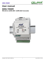
Power Connector
The 3-pole power connector connects to a car battery for power supply. Note that the system
accepts a wide power range of 9 to 36V with in-vehicle power management that includes ig-
nition on/off and system on/off delay time control; please refer to the table on the right for
startup/shutdown control and the above diagram for startup/shutdown process diagram.
Note:
The OS will start the shut-down procedure after the car ignition switches off and will
complete the shutdown procedure within the specied system-off delay time. Please make
sure that system-off delay time is sufcient to allow the OS to shut down completely.
System-on/off Delay Switch
The DIP switch (SW1) on the power board (
X103- EC36
) can be used to turn on or off the sys-
tem at a specic on/off delay time via car ignition. Note that this table shows that same informa-
tion as the one in Chapter 4 ̶ Jumper Settings.
H3
H1
S1
H1
1 2 3 4 5 6 7 8
1
ON
J1
Connector to the external power source
Connector to the DC-in connector of the system board
SW1-2: System-on delay enable/disable
On (Default) Enable (delay time setting adjustable
by SW1-4 and 1-5 as shown in the
table below)
Off Disable (System-on delay = 3 sec)
SW1-4 and 1-5: System-on delay time setting
Congure the number of seconds after which the system will start the power-on process.
4 5 Time
On On 10 sec (default)
Off On 30 sec
On Off 1 min
Off Off 5 min
SW1-3: System-off delay enable/disable
On (Default) Enable (delay time setting adjust-
able by SW1-6, 1-7 and 1-8 as
shown in the table below)
Off Disable (System-off delay = 0 sec)
SW1-6, 1-7 and 1-8: System-off delay time setting*
Congure the number of seconds by which the system will complete the power-off process.
6 7 8 Time
On On On 30 sec (default)
Off On On 1 min
On Off On 3 min
Off Off On 5 min
On On Off 10 min
Off On Off 15 min
On Off Off 30 min
Off Off Off 1 hr
GND
VCC
ACC
Power Board (
X103- EC36
)
System startup process with in-vehicle power control
System shutdown process with in-vehicle power control
Ignition Off
System shuts down
& nishes shutdown
process at the
specied delay time
System
On
System
Off
System
Off
Ignition On
System
On
System boots
Counts down
System-on
delay time
/