Page is loading ...

ADDENDUM TO OPERATING INSTRUCTIONS
FLARE METER RETROFIT SOLUTION:
90° UPGRADE KIT
Main
FLOWSIC100 Flare

2 FLOWSIC100 Flare · Addendum to Operating Instructions · 8020368/ZO11/V1-1/2017-07 · © SICK Engineering GmbH
Document Information
Product
Product name: FLOWSIC100 Flare
Document ID
Title: Addendum to Operating Instructions
FLOWSIC100 Flare
Part No.: 8020368/ZO11
Version: 1-1
Release: 2017-07
Manufacturer
SICK Engineering GmbH
Bergener Ring 27 · D-01458 Ottendorf-Okrilla · Germany
Phone: +49 35205 52410
Fax: +49 35205 52450
E-mail: [email protected]
Trademarks
Windows is a Microsoft Corporation trademark.
Other product names used in this document may also be trade-
marks and are only used for identification purposes.
Original documents
The English version 8020368/ZO11 of this document is an original
document from the manufacturer.
SICK Engineering GmbH assumes no liability for the correctness of
an unauthorized translation.
Please contact the publisher in case of doubt.
Legal information
Subject to change without notice.
© SICK Engineering GmbH. All rights reserved.
Warning Symbols
Warning levels / Signal words
HAZARD
Risk or hazardous situation which will result in severe personal
injury or death.
WARNING
Risk or hazardous situation which could result in severe personal
injury or death.
CAUTION
Hazard or unsafe practice which could result in personal injury or
property damage.
NOTICE
Hazard which could result in property damage.
Information Symbols
Warning
Important technical information for this product
Important information on electric or electronic func-
tions
Supplementary information

Contents
FLOWSIC100 Flare · Addendum to Operating Instructions · 8020368/ZO11/V1-1/2017-07 · © SICK Engineering GmbH 3
1Important Information . . . . . . . . . . . . . . . . . . . . . . . . . . . . . . . . . . . . . . . . . . . . . . . 5
1.1 General information . . . . . . . . . . . . . . . . . . . . . . . . . . . . . . . . . . . . . . . . . . . . . . . . . . . . . . . . . . 6
1.2 For your safety . . . . . . . . . . . . . . . . . . . . . . . . . . . . . . . . . . . . . . . . . . . . . . . . . . . . . . . . . . . . . . . 6
1.3 Transport protection . . . . . . . . . . . . . . . . . . . . . . . . . . . . . . . . . . . . . . . . . . . . . . . . . . . . . . . . . . 6
2 Product Description . . . . . . . . . . . . . . . . . . . . . . . . . . . . . . . . . . . . . . . . . . . . . . . . . . . 7
2.1 System overview . . . . . . . . . . . . . . . . . . . . . . . . . . . . . . . . . . . . . . . . . . . . . . . . . . . . . . . . . . . . . 8
2.2 FLSE100 sender/receiver units . . . . . . . . . . . . . . . . . . . . . . . . . . . . . . . . . . . . . . . . . . . . . . . . 9
2.3 Mounting accessories . . . . . . . . . . . . . . . . . . . . . . . . . . . . . . . . . . . . . . . . . . . . . . . . . . . . . . . 10
3Mounting and Installation . . . . . . . . . . . . . . . . . . . . . . . . . . . . . . . . . . . . . . . . . . 11
3.1 Overview . . . . . . . . . . . . . . . . . . . . . . . . . . . . . . . . . . . . . . . . . . . . . . . . . . . . . . . . . . . . . . . . . . . 12
3.2 Determining the measuring and installation location . . . . . . . . . . . . . . . . . . . . . . . . . . . . 12
3.3 Preparation of measurement point for retrofit . . . . . . . . . . . . . . . . . . . . . . . . . . . . . . . . . . 13
3.3.1 Components that can remain . . . . . . . . . . . . . . . . . . . . . . . . . . . . . . . . . . . . . . . . . . . . . . 13
3.3.2 Components that have to be replaced. . . . . . . . . . . . . . . . . . . . . . . . . . . . . . . . . . . . . . . 14
3.4 Determining the geometrical installation parameters . . . . . . . . . . . . . . . . . . . . . . . . . . . 15
3.5 Assembly . . . . . . . . . . . . . . . . . . . . . . . . . . . . . . . . . . . . . . . . . . . . . . . . . . . . . . . . . . . . . . . . . . . 19
3.5.1 Prerequisites for assembly . . . . . . . . . . . . . . . . . . . . . . . . . . . . . . . . . . . . . . . . . . . . . . . . . 19
3.5.2 Tools required . . . . . . . . . . . . . . . . . . . . . . . . . . . . . . . . . . . . . . . . . . . . . . . . . . . . . . . . . . . . 19
3.5.3 Fitting the sender/receiver units. . . . . . . . . . . . . . . . . . . . . . . . . . . . . . . . . . . . . . . . . . . . 20
3.5.4 Mounting the MCUP Control Unit. . . . . . . . . . . . . . . . . . . . . . . . . . . . . . . . . . . . . . . . . . . . 25
3.5.5 Mounting the adapter plate . . . . . . . . . . . . . . . . . . . . . . . . . . . . . . . . . . . . . . . . . . . . . . . . 25
3.5.6 Mounting MCUP on the adapter plate . . . . . . . . . . . . . . . . . . . . . . . . . . . . . . . . . . . . . . . 27
4 Start-up and Parameter Settings . . . . . . . . . . . . . . . . . . . . . . . . . . . . . . . . . 29
4.1 Sequence of start-up . . . . . . . . . . . . . . . . . . . . . . . . . . . . . . . . . . . . . . . . . . . . . . . . . . . . . . . . 30
4.2 Entering the linearization parameters for the 90° Upgrade Kit . . . . . . . . . . . . . . . . . . 31
5Maintenance. . . . . . . . . . . . . . . . . . . . . . . . . . . . . . . . . . . . . . . . . . . . . . . . . . . . . . . . . . . 33
5.1 Removing the sender/receiver units. . . . . . . . . . . . . . . . . . . . . . . . . . . . . . . . . . . . . . . . . . . 34
6 Specifications . . . . . . . . . . . . . . . . . . . . . . . . . . . . . . . . . . . . . . . . . . . . . . . . . . . . . . . . . 37
6.1 Technical data . . . . . . . . . . . . . . . . . . . . . . . . . . . . . . . . . . . . . . . . . . . . . . . . . . . . . . . . . . . . . . 38
6.2 Dimensional drawings . . . . . . . . . . . . . . . . . . . . . . . . . . . . . . . . . . . . . . . . . . . . . . . . . . . . . . . 39
Contents

Contents
4 FLOWSIC100 Flare · Addendum to Operating Instructions · 8020368/ZO11/V1-1/2017-07 · © SICK Engineering GmbH


6 FLOWSIC100 Flare · Addendum to Operating Instructions · 8020368/ZO11/V1-1/2017-07 · © SICK Engineering GmbH
Important Information
Subject to change without notice
1.1 General information
This document supplements and is to be used only in combination with the
currently valid Operating Instructions FLOWSIC100 Flare (Part No. 8018485).
Special instructions for the FLOWSIC100 Flare 90° Upgrade Kit in this document
overwrite related general information in the Operating Instructions FLOWSIC100
Flare.
1.2 For your safety
1.3 Transport protection
To prevent transport damage, the sender/receiver units must be secured before each
transport according to
Fig. 1.
The transducers must be fully retracted and secured in place with the safety clamp.
Fig. 1 Safety clamp
NOTICE:
Read the Operating Instructions carefully before using the FLOWSIC100
Flare.
Special attention must be paid to all safety instructions and warnings for
assembly, installation and operation of the device!
NOTICE:
This section replaces § 1.5 “Transport safety device for retractable sender/
receiver units” of the Operating Instructions FLOWSIC100 Flare.
1
2
2
1
1 Safety clamp
2 Retraction flange


8 FLOWSIC100 Flare · Addendum to Operating Instructions · 8020368/ZO11/V1-1/2017-07 · © SICK Engineering GmbH
Product Description
Subject to change without notice
2.1 System overview
The 90° Upgrade Kit consists of the following components (for a detailed description see
p. 13, § 3.3):
● FLSE100-EXS 90°sender/receiver units
For sending and receiving ultrasonic pulses, for signal processing and control of system
functions (
p. 9, § 2.2); the sender/receiver units are derived from the FLSE100-EXS
and use special transducer design.
● MCUP control unit (see Operating Instructions FLOWSIC100 Flare § 2.2.4 “MCUP con-
trol unit“)
For control, evaluation and output of the sensor data connected via the RS485 inter-
face
● Connection cable between the sender/receiver units
● Connection cable between sender/receiver units and MCUP
● Alignment tool for correct alignment of the sender/receiver units
Fig. 2 System overview 90° Upgrade Kit
1 Sender/receiver unit (master probe) 3 Sender/receiver unit (slave probe)
2 Alignment tool 4 MCUP control unit
2
31
4

Product Description
FLOWSIC100 Flare · Addendum to Operating Instructions · 8020368/ZO11/V1-1/2017-07 · © SICK Engineering GmbH 9
Subject to change without notice
2.2 FLSE100 sender/receiver units
Fig. 3 Schematic overview sender/receiver unit FLOWSIC100 Flare 90° Upgrade Kit
Material for gas-affected parts (standard configuration)
1 Electronics unit 6 Ground terminal
2 Connection 7 Retraction flange
3 Pressure balance element 8 Duct probe
4 Safety clamp 9 Transducer
5 Compression ring
1 2 3 7 8
6
Sensor length
54 9
Material Component
Type FLSE100
EXS 90° non-retract. retract.
Stainless steel
1.4571
Connection for optional venting, retraction flange, sensor
contour
xN/Ax
Titanium Duct probe, transducer x N/A x
PTFE
Sealing duct probe in retraction flange at operating
conditions
xN/Ax
PTFE, with
graphite
Sealing duct probe in retraction flange at maintenance
conditions
xN/Ax

10 FLOWSIC100 Flare · Addendum to Operating Instructions · 8020368/ZO11/V1-1/2017-07 · © SICK Engineering GmbH
Product Description
Subject to change without notice
Type code
3)
Flange connection prepared for mounting on counter flange 3" CL150 RF acc. to ASME
B16.5
Application area, configurations
Versions for low-temperature range -196 ... +100°C on request
2.3 Mounting accessories
All accessories necessary for installation of the FLOWSIC100 Flare 90° retrofit solution are
included in the 90° Upgrade Kit and described in this document.
NOTICE:
This section supplements § 2.2.1.1 “Type code for sender/receiver units ATEX
Zone 1, IECEX and Zone 2“ of the Operating Instructions FLOWSIC100 Flare.
The type code has been extended for the FLOWSIC100 Flare 90° Upgrade Kit.
Parameter Code Design/Description Type of sender/receiver unit
NL
924 For pipelines up to 24“ FLSE100-EXS 90°, retractable
3)
948 For pipelines up to 48“ FLSE100-EXS 90°, retractable
3)
972 For pipelines up to 72“ FLSE100-EXS 90°, retractable
3)
Sealing material in
retraction mechanism M Metal
Type of sender/
receiver unit
Gas temperature
[°C]
Pressure
[barg]
Active measuring
path
[mm]
Pipe diameter
[mm]
NL
[mm]
standard range high temperature range
FLSE100-EXS 90° -70 ... +180 -70 ... +280°C
19
full ANSI
150...374 300 ... 1800
(12" ... 72")
N/A
Sensor length
see
p. 9, § 2.2
NOTICE:
This section replaces § 2.2.2 “Mounting Accessories“ of the Operating
Instructions FLOWSIC100 Flare.

Mounting and Installation
FLOWSIC100 Flare · Addendum to Operating Instructions · 8020368/ZO11/V1-1/2017-07 · © SICK Engineering GmbH 11
Subject to change without notice
FLOWSIC100 Flare
3 Mounting and Installation
Overview
Determining the measuring and installation location
Preparation of measurement point for retrofit
Determining the geometrical installation parameters
Assembly

12 FLOWSIC100 Flare · Addendum to Operating Instructions · 8020368/ZO11/V1-1/2017-07 · © SICK Engineering GmbH
Mounting and Installation
Subject to change without notice
3.1 Overview
To install the FLOWSIC100 Flare 90° Upgrade Kit, proceed as follows:
Ensure suitable mounting conditions and sufficient clearance space for installation,
p. 12, § 3.2.
Prepare the measurement point for retrofit,
p. 13, § 3.3.
Determine the geometrical installation parameters,
p. 15, § 3.4.
Install the sender/receiver units and the MCUP control unit,
p. 19, § 3.5.
3.2 Determining the measuring and installation location
The 90°Upgrade Kit serves to replace an existing installation; the installation location must
fullfil the following requirements:
● Counter flange: CL150 RF acc. ASME B16.5, full bore
● Minimum inner diameter of existing nozzle and ball valve: 50 mm
Clearance for fitting/removing the sender/receiver units
Fig. 4 Clearance for fitting/removing the sender/receiver units
Sender/receiver units designed to fit counter flange CL150 RF acc. ASME B16.5
NOTICE:
This section replaces § 3.1.1 “Determining the measuring and installation
location“of the Operating Instructions FLOWSIC100 Flare.
b
1 2 3 4
1 Sender/receiver unit
2 Ball valve
3 Nozzle
4 Pipeline
Type
NL
(acc. type
code)
Retractable b
mm (inch)
FLSE100-EXS 90°
924 x 1048 (41.3) + length of ball valve and nozzle
948 x 1170 (46.1)+ length of ball valve and nozzle
972 x 1291 (50.8) + length of ball valve and nozzle

Mounting and Installation
FLOWSIC100 Flare · Addendum to Operating Instructions · 8020368/ZO11/V1-1/2017-07 · © SICK Engineering GmbH 13
Subject to change without notice
3.3 Preparation of measurement point for retrofit
Prior to the installation of the FLOWSIC100 Flare retrofit solution, the measurement point
has to be prepared. Some components of the existing installation have to be replaced while
others can remain and be used again.
The following schematic drawing shows an application overview with the components that
can remain (green colored).
Fig. 5 System overview showing already replaced SICK sensors [4] and SICK electronics unit [5]
3.3.1
Components that can remain
Nozzles / Shut-off Valves [1]
Since existing nozzles and shut-off valves can be used, no hot-tapping or depressurization
of the Flare gas line is needed.
Check the correct function and leak tightness of the nozzles and shut-off valves. The
sealing face of the shut-off valve shall not be damaged and has to be clean and free of
corrosion in order to ensure the correct fit of the new gaskets.
p/T Transmitters [2]
The existing pressure and temperature transmitters can remain and be used again.
Check the correct function of the transmitters.
Cables [3]
Most cables going to the electronics unit of the existing flare gas meter can be used again if
the SICK electronics unit is mounted at the same location.
The following cables can remain:
● Connection cable p/T Transmitter to electronics unit
● Power supply cable
● Connection cable SCADA /DCS System to electronics unit
3UHVVXUHWUDQVPLWWHU
7HPSHUDWXUHWUDQVPLWWHU
3RZHUFDEOH
&RPSRQHQWV\RXFDQNHHS
&DEOHV\RXFDQNHHS
1HZFDEOHV
&DEOHWR6&$'$
1
4
6
7
3
5
3
2

14 FLOWSIC100 Flare · Addendum to Operating Instructions · 8020368/ZO11/V1-1/2017-07 · © SICK Engineering GmbH
Mounting and Installation
Subject to change without notice
3.3.2 Components that have to be replaced
Ultrasonic Transducers [4]
The ultrasonic transducers are the actual flow sensors and have to be replaced. The
existing ultrasonic transducers have to be removed from the flare gas line.
After retraction of the ultrasonic transducers make sure that the shut-off valve is closed
tightly and covered with a blind flange to prevent soiling.
The installation of the SICK ultrasonic transducers is described in
p. 20, § 3.5.3.
Electronics Unit [5]
The electronics unit is the central component that powers the ultrasonic transducers, does
calculations and transmits data to SCADA/DCS. The existing electronics unit has to be
removed.
Carefully unplug and disconnect all connected cables. Do not use a wire cutter if the
cables shall be reused. Mark the cables that shall be reused according to their function
and polarity [e.g. p/T, 24V,…]
The FLOWSIC100 Flare retrofit scope contains an adapter plate to mount the SICK elec-
tronics unit (MCUP) at the original location.
The installation of the SICK electronics unit (MCUP) including the adapter plate is
described in
p. 25, § 3.5.5.
Cables [6] + [7]
● The existing connection cable between the ultrasonic transducers [4] and the electron-
ics unit [5] cannot be reused and has to be removed.
● The interconnection cable between the SICK ultrasonic transducers [6] is part of the
FLOWSIC100 Flare retrofit scope and will be delivered as accessory.
● The connection cable [7] between the SICK ultrasonic transducer [4] and the SICK elec-
tronics unit (MCUP) [5] is not part of the FLOWSIC100 Flare retrofit scope of delivery
and has to be installed by plant operator. SICK uses an industry standard twisted pair
cable:
– Li2YCYv(TP), 2x2x0.5 mm² twisted pair; with reinforced black outer sheath
– Maximum length: 1000m (3300ft)
This cable must be sourced locally.
NOTICE:
If your cables are installed in conduits, consider the use of a taut wire when
retracting the existing cables to reuse the conduits.
NOTICE: Explosion hazard
Electrical installation shall be carried out acc. to IEC 60079-14.
In addition national and/or local regulations have to be considered.
– In the US install acc. to the NEC.
– In Canada install acc. to CEC part 1.

Mounting and Installation
FLOWSIC100 Flare · Addendum to Operating Instructions · 8020368/ZO11/V1-1/2017-07 · © SICK Engineering GmbH 15
Subject to change without notice
3.4 Determining the geometrical installation parameters
Exact values for geometrical installation parameters must be calculated to lower the
uncertainty of measurement.
● The following parameters must be calculated:
● Path Angle between ultrasonic transducers [α]
● Path Length between ultrasonic transducers [L]
● Pipe Diameter [Di]
● Cross-sectional Area of the pipe [Area]
Furthermore the Setup Distance [A] will be calculated which is needed for the correct
installation of the ultrasonic sender / receiver units (
p. 20, § 3.5.3).
Calculation input values
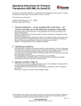
Fig. 6 Geometry Calculation (example)
NOTICE:
This chapter replaces § 3.3.1.4 “Determine path angle and path length“ of the
Operating Instructions FLOWSIC100 Flare.
The Geometry Calculator software to perform these calculations can be found
on the Product CD.
NOTICE: Maximum tolerances
● Maximum tolerances of the input values dimensions.
● Maximum tolerance ± 1 mm / ± 1 °
NOTICE: Unit input values
The units of the input values can be altered by clicking into the unit cell. A Drop-
down menu will give you different metric and imperial possibilities.
Project:
TAG Number:
Customer:
Contact name:
Address:
Input values:
a Nozzle distance 240,00 mm
E Ray rescue angle 12,00 °
J Path angle nominal 45,00 °
Results:
L
Path length 0,202 m
Į Path angle 46,12 °
Geometry Calculation
FLOWSIC100 FLARE 90°UPGRADE KIT

16 FLOWSIC100 Flare · Addendum to Operating Instructions · 8020368/ZO11/V1-1/2017-07 · © SICK Engineering GmbH
Mounting and Installation
Subject to change without notice
1 Nozzle Distance [a]: Distance between the two mid-points of the existing weld-on noz-
zles. Measure this value as shown in
Fig. 7.
Fig. 7 Nozzle Distance [a]
2 Ray Rescue Angle [β]
For an optimized adjusted measuring system for high velocities a turning of sensor B is
recommended. A ray rescue angle of 12° should be realized. The delivered alignment
tool can be used for easy adjustment during mechanical installation.
3 Nominal path angle [γ]
The nominal path angle is defined by the center point of the nozzle of sensor a referring
to the axial pipe direction. This value will be used for calculation of path length and real
path angle α.
4 Real path angle [α]
Real path angle is defined by the center points of the sensor membranes referring to
the axial pipe direction. This value is different to the Nominal path angle because of the
used ray rescue angle. It has to be entered in the SOPAS program for firmware configu-
ration of the whole system.
5 Ultrasonic sensor type
The type of the installed ultrasonic sensors has to be set. You can find the type descrip-
tion on the type plate of the ultrasonic sensor.
6 Sensor length
SICK supports 3 different standard transducer lengths to achieve an optimized installa-
tion space referring to the pipe size. The sensor length is defined from the bottom of the
metal screw till the center point of the membrane. The geometry calculator sets the cor-
rect sensor length automatically when choosing the installed ultrasonic sensor type.
7 Pipe Circumference [u]
Measure the outer circumference of the pipe with a measuring tape.
8 Wall thickness [s]
The wall thickness can be found in the commissioning documentation or in the program
parameter sheet of the existing flare meter.
a
Type plate Nominal Pipe Size
FLSE100-EXS 924... Up to 24"
FLSE100-EXS 948... Up to 48"
FLSE100-EXS 972... Up to 72"

Mounting and Installation
FLOWSIC100 Flare · Addendum to Operating Instructions · 8020368/ZO11/V1-1/2017-07 · © SICK Engineering GmbH 17
Subject to change without notice
Calculation results
Fig. 8 Ultrasonic transducer installation
Setup Distance [A] = Sensor length - Wall thickness - 0.4 * Radius (inside)
Wall Thickness

18 FLOWSIC100 Flare · Addendum to Operating Instructions · 8020368/ZO11/V1-1/2017-07 · © SICK Engineering GmbH
Mounting and Installation
Subject to change without notice
Fig. 9 Top to buttom view (schematic)
The results of the calculation are needed for the correct installation (
p. 19, § 3.5) and
commissioning (
p. 30, § 4.1) of the FLOWSIC100 Flare 90° Upgrade Kit.

Mounting and Installation
FLOWSIC100 Flare · Addendum to Operating Instructions · 8020368/ZO11/V1-1/2017-07 · © SICK Engineering GmbH 19
Subject to change without notice
3.5 Assembly
3.5.1 Prerequisites for assembly
The pressure in the pipe line does not exceed the maximum installation pressure of
0.5 bar (g).
Preparation work has been completed,
p. 13, § 3.3.
Fig. 10 Measurement point prepared for retrofit
3.5.2
Tools required
● Jaw wrench size 24
● Jaw wrench size 50
● Allen key size 4
● Folding rule
WARNING: Maximum pressure for use of the retraction mechanism
Maximum pressure for use of retraction mechanism: 0.5 bar (g)
Installation/demounting is possible up to 5.5 bar (g) with an additional
extraction tool (available on request).
Flow directionFlow direction
A - Upstream ball valve B - Downstream ball valve

20 FLOWSIC100 Flare · Addendum to Operating Instructions · 8020368/ZO11/V1-1/2017-07 · © SICK Engineering GmbH
Mounting and Installation
Subject to change without notice
3.5.3 Fitting the sender/receiver units
Fig. 11 Overview
To install the sender/receiver units, proceed as follows:
NOTICE:
Observe the notes given for the installation of the sender/receiver units in
§ 3.6 “General notes for installation of sender/receiver units“ of the
Operating Instructions FLOWSIC100 Flare.
Observe the saftey notes given in § 1 “Important Information“ of the
Operating Instructions FLOWSIC100 Flare.
1
1 Electronics unit 6 Mounting kit
2 Duct probe 7 Ball valve
3 Safety clamp 8 Nozzle
4 Clamping ring screw connection 9 Pipeline
5 Retraction flange
2 3
4
5 6 7 8 9
1 2 3
4
5 7 8 9
NOTICE:
SICK recommends to install the sender/receiver units with two persons.
/