Digital Watchdog DWC-MB94Wi28T, DWC-MB94Wi36T User manual
- Category
- Security cameras
- Type
- User manual

Default Login Information
Username: admin
Password: admin
Default IP Address
192.168.226.201
※ The picture might differ according to the specification and model.
※ Contents of this user manual are protected under copyrights and computer program laws.
Rev: 11/20
Before operating the system, please read this User Manual and retain it for future reference.
USER MANUAL

Notes on Safety
• This product is intended to be supplied by a Listed Power Unit, marked with 'Limited Power Source', 'LPS'
on the unit, output rated minimum 12V/2 A or POE 48V/ 350mA or AC24V (depending on models), no
more than 2000m altitude of operation and Tma=60 Deg.C.
• For modes with PoE function, the function of the ITE being investigated to IEC 60950-1 standard is
considered not likely to require connection to an Ethernet network with outside plant routing, including
campus environment and the ITE is to be connected only to PoE networks without routing to the outside
network.
• Do not attempt to disassemble the camera; to prevent electric shock, do not remove screws or covers.
• There are no user-serviceable parts inside. Please contact the nearest service center as soon as possible if
there is any failure.
• Avoid incorrect operation, shock vibration, heavy pressing which can cause damage to the product.
• Do not use harsh detergent to clean the camera body. If necessary, please use a soft dry cloth to wipe dirt;
for hard contamination, use neutral detergent. Any cleanser for high-grade furniture is applicable.
• Avoid aiming the camera directly towards extremely bright objects such as the sun, as this may damage
the image sensor.
• Please follow the instructions to install the camera. Do not reverse the camera, or the reversing image will
be received.
• Do not operate it in case temperature, humidity, and power supply are beyond the limited stipulations.
• Keep away from heat sources such as radiators, heat registers, stoves, etc.
• Do not expose the product to the direct airflow from an air conditioner.
• This manual is for using and managing the product. We may reserve the rights of amending the
typographical errors, inconsistencies with the latest version, software upgrades and product improvements,
interpretation, and modification. These changes will be published in the latest version without special
notification.
• All pictures, charts, images in this manual are only for description and explanation of our products. The
ownership of trademarks, logos and other intellectual properties related to Microsoft, Apple and Google
belong to the above-mentioned companies.
Disclaimer
• Regarding the product with internet access, the use of the product shall be wholly at your risks. Our
company shall be irresponsible for abnormal operation, privacy leakage or other damages resulting from
cyber-attack, hacker attack, virus inspection, or other internet security risks; however, Our company will
provide timely technical support if necessary.
• Surveillance laws vary from country to country. Check all laws in your local region before using this product
for surveillance purposes. We shall not take the responsibility for any consequences resulting from illegal
operations.
Regulatory Information
FCC Marking
The products have been tested and found in compliance with the council FCC rules and regulations
part 15 subpart B. Operation of this product is subject to the following two conditions: (1) this device may
not cause harmful interference, and (2) this device must accept any interference received, including
interference that may cause undesired operation.
RoHS
The products are designed and manufactured according to Directive EU RoHS Directive 2011/65/EU
and its amendment Directive EU 2015/863 on the restriction of the use of certain hazardous substances in
electrical and electronic equipment.

Table of Contents
1
Introduction .................................................................................................................................................................................. 5
Product and Accessories .................................................................................................................................................................... 5
Part Name .................................................................................................................................................................................................. 6
2 Installation ..................................................................................................................................................................................... 7
Installing the camera ........................................................................................................................................................................... 7
Adjusting the Camera’s Angle .................................................................................................................................................. 7
Cabling ................................................................................................................................................................................................... 8
Inserting/Removing the SD Card ............................................................................................................................................ 9
3 Live View ...................................................................................................................................................................................... 10
4 Camera Configuration ............................................................................................................................................................. 11
System Configuration......................................................................................................................................................................... 11
4.1.1 Basic Information ................................................................................................................................................................ 11
4.1.2 Date and Time ....................................................................................................................................................................... 11
4.1.3 Local Config. ......................................................................................................................................................................... 12
4.1.4 Storage ..................................................................................................................................................................................... 13
Image Configuration .................................................................................................................................................................... 14
4.2.1 Display Configuration ...................................................................................................................................................... 14
4.2.2 Video / Audio Configuration........................................................................................................................................ 16
4.2.3 OSD Configuration ............................................................................................................................................................ 17
4.2.4 Video Mask ............................................................................................................................................................................ 18
4.2.5 ROI Configuration .............................................................................................................................................................. 19
4.2.6 Lens Control .......................................................................................................................................................................... 19
Alarm Configuration .................................................................................................................................................................... 20
4.3.1 Motion Detection ............................................................................................................................................................... 20
4.3.2 Other Alarms ........................................................................................................................................................................ 21
4.3.3 Alarm In .................................................................................................................................................................................. 22
4.3.4 Alarm Out .............................................................................................................................................................................. 23
4.3.5 Alarm Server ........................................................................................................................................................................ 24
Event Configuration .................................................................................................................................................................... 25
4.4.1 Video Tampering Detection ........................................................................................................................................ 25
4.4.2 Line Crossing ....................................................................................................................................................................... 26
4.4.3 Perimeter Intrusion ........................................................................................................................................................... 28
Network Configuration .............................................................................................................................................................. 30
4.5.1 TCP/IP ...................................................................................................................................................................................... 30
4.5.2 Port ............................................................................................................................................................................................ 31
4.5.3 DDNS ........................................................................................................................................................................................ 31
4.5.4 SNMP........................................................................................................................................................................................ 32
4.5.5 802.1x ....................................................................................................................................................................................... 32
4.5.6 RTSP ......................................................................................................................................................................................... 33
4.5.7 UPnP ......................................................................................................................................................................................... 34
4.5.8 E-mail ....................................................................................................................................................................................... 34
4.5.9 FTP ............................................................................................................................................................................................ 35
4.5.10 HTTPS ................................................................................................................................................................................ 35
4.5.11 QoS ........................................................................................................................................................................................... 35
Security Configuration ............................................................................................................................................................... 36
4.6.1 User Configuration ........................................................................................................................................................... 36
4.6.2 Online User ........................................................................................................................................................................... 37
4.6.3 Block and Allow Lists ...................................................................................................................................................... 37
4.6.4 Security Management..................................................................................................................................................... 38
Maintenance Configuration ..................................................................................................................................................... 39
4.7.1 Backup and Restore ........................................................................................................................................................ 39

4.7.2 Reboot..................................................................................................................................................................................... 39
4.7.3 Upgrade .................................................................................................................................................................................. 39
4.7.4 Operation Log ..................................................................................................................................................................... 39
5
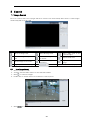
Search ..........................................................................................................................................................................................40
Image Search ....................................................................................................................................................................................... 40
5.1.1 Local Image Search ......................................................................................................................................................... 40
5.1.2 SD Card Image Search .................................................................................................................................................... 41
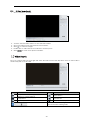
Video Search .................................................................................................................................................................................... 41
5.2.1 Local Video Search........................................................................................................................................................... 42
5.2.2 SD Card Video Search .................................................................................................................................................... 42
5.2.3 Video clip and downloading ....................................................................................................................................... 43
6 Appendix .................................................................................................................................................................................... 44
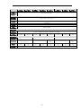
Troubleshooting ..................................................................................................................................................................................44
Dimensions ....................................................................................................................................................................................... 45
DWC-MB94Wi28T, DWC-MB94Wi36T........................................................................................................................................ 45
Specifications .................................................................................................................................................................................. 46
7 Warranty Information ............................................................................................................................................................ 48
8 Limits and Exclusions ............................................................................................................................................................ 49

-5-
1
Introduction
Product and Accessories
Please make sure the camera and accessories listed below are included in the package:

-6-
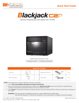
Part Name
No.
Description
1
Fixed Ring
2
Mounting Base
3
Network Input
4
Audio Input
5
Power Input
6
Micro SD Card Slot
7
Reset Button
8
Sunshield Cover

-7-
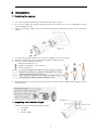
2
Installation
Installing the camera
1. The mounting surface must bear five times the weight of your camera.
2. Do not let the cables get caught in improper places or the electric line cover to be damaged. This may
cause a breakdown or fire.
3. Using the mounting template sheet or the camera itself, mark and drill the necessary holes in the wall or
ceiling.
4. Pass wires through and make all connections. See “Cabling” for more information.
5. Attach the main body to the mount bracket by tightening the lock screw.
6. To use the camera’s waterproof wiring:
a.
Install the LAN cable into ‘a’.
b.
’b’ will be assembled to ‘a’ with a 1/4 turn.
c.
Thread ‘c’ tightly to ‘b’.
7. Once all cables are connected to the camera, secure the camera to the mounting surface using the four (4)
included screws.
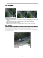
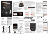
Adjusting the Camera’s Angle
Adjust the camera’s tilt and angle using its bracket.
• Pan: 360°
• Tilt: 90°
• Rotation: 360°
NOTE: To ensure moisture seal, make sure the o-
ring is in place
between (a) and (b). In extreme environments use of an
outdoor rated sealer is recommended.
NOTE: When using the waterproof cap, crimp the RJ45 connector
after passing the cable through the waterproof cap.

-8-
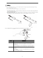
Cabling
Use a PoE-enabled switch to connect data and power through a single cable and begin viewing
and recording images instantly.
A non-PoE switch will require an adaptor for power transmission.
1. NETWORK CONNECTIONS – Using a PoE Switch or PoE Injector, connect the camera using an Ethernet
cable for both data and power.
2. NETWORK CONNECTIONS – Not using PoE Switch or PoE Injector, connect the camera to the switch
using an Ethernet cable for data transmission and use a power adapter to power the camera.
Use the diagram below to connect all supported external devices to the camera.
No.
Description
Network Cable
Connect a crossover cable into the RJ-45 port.
Audio Input Connect the ‘audio in’ port of the camera to the microphone
directly or 'line out’ port of the amplifier connected with a
microphone.
If the microphone is connected directly, the microphone with the
embedded amplifier such as condenser mic. needs to be used.
Power Input
Please, check the voltage and current capacity of the rated power
carefully.
Power requirements: DC12V, PoE (IEEE 802.3af class 3). Adapter
not Included.
Power consumption: <9.5W

-9-
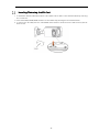
Inserting/Removing the SD Card
1. To install the camera’s SD Card, locate the SD card slot at the base of the camera module by removing
the cover dome.
2. Insert class 10 SD/SDHC/SDXC card into the SD card slot by pressing the SD card until clicks.
3. To remove the SD card, press the card inward until it clicks to release from the card slot then pull out
from the slot.

-10-
3
Live View
1. Open an Internet Explorer (IE) web browser.
2. Enter the camera’s IP address in the address bar. Enter the camera’s username and password (default
username and password are admin | admin).
3. You may be prompted to install the NetAIIPCamera plug-in to view video from the camera. Click on the
link above the login to download and install the plug-in.
4. When logging into the camera for the first time, you will be prompted to change the default admin
password. It is highly recommended that you change the camera’s default password.
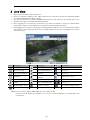
5. After logging into the camera’s web viewer, the following window will be shown. The camera’s view includes
four (4) tabs on the top right, that allow users to navigate between the live view, configuration menu, search
video and log out.
Icon
Description
Icon
Description
Icon
Description
Original size
Sensor alarm indicator*
Start/stop local recording
Fit correct scale
Motion alarm indicator
Zoom in
Auto (fill the window)
Color abnormal
indicator
Zoom out
Fullscreen
Abnormal clarity
indicator
Auto Zoom control*
Start/stop live view
Scene change indicator
Zoom -/+
Start/stop two-way
audio*
Line crossing indicator
Focus -/+
Enable/disable audio*
Intrusion indicator
SD card recording indicator*
Snapshot
* NOTE: Functions above may be disabled based on the camera model.
In fullscreen mode, double-click anywhere on the screen or press the ESC key on the keyboard to exit
the fullscreen.

-11-
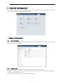
4
Camera Configuration
To access the camera’s settings and configuration, click on the ‘Config.’ tab on the top right side of the camera’s
main view. The following setting options will be available:
System Configuration
4.1.1
Basic Information
This option shows the camera’s basic network information. Users can adjust the device’s name, view the current
settings version and MAC address.
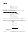
4.1.2
Date and Time
Open this setup page to configure the camera’s date, time, and time zones as needed.
It is always recommended to setup the camera’s date and time when you access the camera for the first time to
avoid issues with recording or events.
Choose the correct time zone from the drop-down menu options.

-12-
If needed, enable the daylight savings time (DST). You can set the DST settings to apply automatically, or
manually enter the start and end time for the DST period.
When setting up the camera’s time, users can select to synchronize the camera with an NTP server. If enabled,
enter the server’s address and how often the time synchronization will take place.
You can also set the camera to synchronize with a local computer or enter the time for the camera manually.
4.1.3
Local Config.
For screen captures and event images, a path must be set in the local directory where images will be saved. Use
this configuration screen to select the directory path for captured pictures and recorded videos on the local PC.
Users can also enable or disable the bitrate display in the recorded files.
“Local smart snapshot storage” assigns captured pictures triggered by smart events (line crossing, intrusion, etc.)
to be saved to the local PC.

-13-
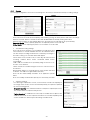
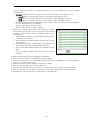
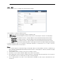
4.1.4
Storage
The Storage Configuration screen lets users manage the SD card (not included) and setup recording settings.
• SD Card Management
Users can check the total SD card capacity and remaining storage for both pictures and video recordings.
Click the “Format” button to format the SD card. All data will be cleared by clicking this button.
Click the “Eject” button to stop writing data to the SD card. Then the SD card can be ejected safely.
Snapshot Quota
: Set the capacity proportion of captured pictures on the SD card.
Video Quota
: Set the capacity proportion of record files on the SD card.
• Schedule Recording Settings
Users can select the stream to record, add pre-recording time, and
select whether to override old data when the SD card is full. Users
can also setup a recording schedule for the camera by checking the
box under ‘Timing’. The schedule below will appear.
Select which hours, from 0 to 24, for each day, will have SD card
recording enabled. Green means scheduled. Blank means
unscheduled.
“Add”: Add the schedule for a special day. Drag the mouse to set
the time on the timeline.
“Erase”: Delete the schedule. Drag the mouse to erase the time on
the timeline.
Manual Input: Click it for a specific day to enter specific start and
end times. This adds more granularities (minutes).
Users can also add “Holiday Schedule” to be applied to special
dates.
Note: The holiday schedule takes priority over the weekly schedule.
• Snapshot Settings
For still images captured for events, set the format, resolution and quality of
the image. Users can also set the interval and quantity of snapshots captured
by each event triggered.
Snapshot Quantity
: The maximum number of snapshots captured per event.
The actual number of snapshots may be less.
Timing Snapshot
: If enabled, users can setup a schedule when snapshots are
enabled. Users must set the snapshot interval for the schedule separately and
set the schedule the same way the Recording Schedule works.

-14-
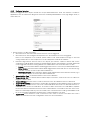
Image Configuration
The Image Configuration menu includes Display, Video/Audi o, OSD, Video Mask and ROI Configuration.
4.2.1
Display Configuration
The image’s settings can be adjusted from this screen. The setting screen includes a small preview of the
camera’s view to see the applied settings for a more accurate setup.
Users can also set different profiles for day and night modes.
Settings are applied and saved automatically unless indicated otherwise.
•
Brightness:
The higher the number, the brighter the image will be. The default value is 25.
•
Contrast
: The higher the number, the more contrast between colors will appear in the image. The default
value is 50.
•
Hue
: Set the total color degree of the image. The default value is 50.
•
Saturation
: Set the degree of color purity. The purer the color, the brighter the image is. The default is
50.
•
Sharpness
: Check the box to enable. The higher the number, the sharper lines in the image will appear.
The default is 50.
•
Noise Reduction
: Check the box to enable. Reduce the digital noise in the camera. The higher the value,
the more noise will be removed from the image, but it will also reduce the image resolution. The default
is 30.
•
Defog:
Check the box to enable. When enabled, the camera will compensate and improve the image in
case of a foggy, dusty, smoggy, or rainy environment to get clear images. The default value is 50.
•
Lens Distortion Correction:
Check the box to enable. When the image appears distorted this feature
is used to correct that. The default value is 80 (Available only on supporting models).
• Backlight Compensation (BLC): Select from the following drop-down options:

-15-
o Off: disable backlight compensation. Default mode.
o HWDR: True WDR adjusts the camera to provide a better image when there are both very
bright and very dark areas in the field of view. If enabled, the camera recording will be stopped
for a few seconds while HWDR is turning on.
o HLC: This option lowers the brightness of the entire image by suppressing the image’s bright
area and reducing the size of the halo area.
o BLC: When enabled, the auto exposure will activate according to the scene so that objects in
the darkest area will be seen clearly.
•
HFR
: High Frame Rate. If enabled, the system will restart with the mainstream’s maximum frame rate
can be set to 60fps.
•
Anti-flicker
:
o Off: disable the anti-flicker function. This is used mostly in outdoor installations (default).
o 50Hz: reduce flicker in 50Hz lighting conditions.
o 60Hz: reduce flicker in 60Hz lighting conditions.
•
Smart IR
: This function avoids image overexposure and underexposure by controlling the brightness of
the IR lights according to the environmental conditions. This feature is disabled by default.
•
White Balance
: Adjust the color temperature according to the environment.
o
Auto
: Adjust the color temperatures automatically based on the current environment (default).
o
Indoor
: Adjust the color temperature for indoor installations.
o
Outdoor
: Set the color temperature for outdoor installations.
o
Manual
: Set the color temperature manually. If selected, adjust the Red Gain bad Blue Gain
values as needed.
•
Frequency
: 50Hz and 60Hz can be optional (Default value is 60Hz).
•
Day/Night Mode
:
o
Auto
: The camera will switch between color and B/W modes automatically based on the
lighting conditions (default). Adjust the light sensitivity from the drop-down option (Mild is the
default value). If needed, users can add a delay, in seconds, before the camera switches
between color and B/W.
o
Day
: The camera will remain in color mode regardless of the lighting conditions.
o
Night
: The camera will remain in B/W mode regardless of the lighting conditions.
o
Timing
: If selected, set the hours when the camera will switch to color (daytime) and B/W
(night-time).
•
Infra-red Mode
: Choose “Auto”, “ON” or “OFF”.
•
Exposure Mode
:
o Auto: The camera’s exposure is adjusted automatically based on the lighting conditions
(default).
o Manual: Manually dust the digital shutter speed.
•
Gain Mode and limit
: Select from auto (default) and manual. If the gain mode is set to auto, adjust the
gain limit (default is 50). If “Manual” is selected, adjust the gain value (50 is the default).
•
Corridor Pattern
: Corridor modes are for situations such as long hallways, where the camera is mounted
at a sharp angle to capture the entire scene. 0°, 90°, 180° and 270° options are available. The default
value is 0. The video resolution should be 2.1MP/1080p or lower if this function is used.
•
Image Mirror
: Turn the current image horizontally.
•
Image Flip
: Turn the current image vertically.
Users can setup a schedule for the different profiles to go into effect. To enable, click on the “Schedule” tab
on the top left and select “Timing” from the Schedule drop-down options.
Drag the time bar icons to set the time of day and night. Blue means day time and blank means night time.

-16-
If the current mode of camera parameters is set to schedule, the image configuration mode will
automatically switch between day and night according to the schedule.
4.2.2
Video / Audio Configuration
Set the resolution, frame rate, bitrate type, and video quality and so on subject to the actual network
condition.
Three video streams can be adjustable.
•
Resolution
: Select the resolution for each stream from the drop-down options.
•
Frame rate
: The higher the frame rate, the video is smoother. The maximum value is 30 unless HFR is
enabled under Display Settings.
•
Bitrate type
: Select from CBR and VBR. If CBR is selected, no matter how much change is seen in the
video scene, the compression bitrate will remain constant. If VBR is selected, the compression bitrate
will vary according to scene changes. This can help optimize network bandwidth usage.
•
Bitrate
: When the bitrate mode is set to CBR, adjust the bitrate in Kbps. The higher the bitrate, the
better the image quality will be.
•
Video Quality
: hen bitrate type is set to VBR, adjust the video quality from the drop-down options. The
higher the image quality, the more bitrate will be required.
•
I-Frame interval
: Determine how many frames are allowed between a “group of pictures”. If there is not
much movement in the scene, setting the I-Frame value higher than the frame rate can result in less
bandwidth usage. If the I-Frame value is set too high, and there are frequent changes in the scene, there
is a risk of frame skipping.
•
Video Compression:
Select the compression for each stream from H.265, H.264, or MJPEG (MJPEG is
not available for the mainstream). When selecting H.265, make sure the client system supports this
codec. Compared to H.264, H.265 reduces the transmission bitrate under the same resolution, frame
rate and image quality.
•
Profile
: When selecting H.264 as the compression, select the applicable profile. Baseline, main and high
profiles are selectable.
•
Send Snapshot
: Select which stream will capture snapshots when events occur.
•
Video encode slice split
: When enabled, the camera will stream a smooth image through a low-
performance PC.
•
Watermark
: If enabled a watermark will be added to the recorded video. The watermark text can be
entered by the user as needed.

-17-
For cameras with audio input, microphone built-in, or audio output, click the “Audio” tab to go to the
interface as shown below.
•
Audio Encoding
: Select the audio encoding from the drop-down menu. G711A and G711U are selectable.
•
Audio Type
: If the camera has a built-in microphone, select to enable audio input from the microphone
or external audio input (LIN).
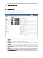
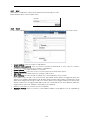
4.2.3
OSD Configuration
The OSD settings page allows users to set up a text overlay on the video, showing the date and time, device
name, etc.
To set a timestamp, device name, or OSD content and picture overlap, check the box next to each field. For the
time stamp, select the date and time format you wish to use. For all other settings, enter the text that will appear
over the camera’s video. Once enabled, users can click-and-drag the text frames to the desired position on the
camera’s preview screen. Click the “Save” button to save the settings.

-18-
Picture Overlay Settings:
The cameras support a picture overlay option. When selected, click “Browse” to select the overlapping picture.
Then click “Upload” to upload the picture. The overlapping image should not exceed 200x200 pixels, or the
upload will fail.
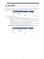
4.2.4
Video Mask
To set up privacy masks in the camera’s view, check the enable button on this menu page. The camera supports
up to 4 separate zones.
To set up a video privacy mask:
1. Check the box next to “Enable”.
2. Click the “Draw Area” button. Use the mouse cursor to drag and draw the mask area on the camera’s
preview.
3. Click the “Save” button to save the settings.
4. Return to the live to verify that the area has been drawn as shown as blocked out in the image.
To c lear the video mask:
Click the “Clear” button to delete the current mask area.

-19-
4.2.5
ROI Configuration
An area in the image can be set as a region of interest. This area will have a higher bitrate than the rest of the
image, resulting in better image quality for the identified area.
1. Check the box next to “Enable”.
2. Click the “Draw Area” button. Use the mouse cursor to drag and draw the ROI area on the camera’s
preview.
3. Set the quality level. The higher the number, the higher the video quality in the ROI will be.
4. Click the “Save” button to save the settings.
5. Return to the live to verify that the area has been drawn as shown as blocked out in the image.
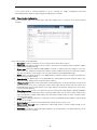
4.2.6
Lens Control
This function is available for models with a motorized zoom lens (DWC-MT9 4WiAT and DWC-MV94WiAT).
Use this setup screen to adjust the camera’s zoom and focus.
Users can manually adjust the camera’s zoom and focus from the live view, or this preview settings page. Users
can also select to switch the focus when the camera switches between color and B/W.
If the camera still appears to be out of focus, use the “One Key Focus” to adjust the focus automatically based
on the camera’s current view.

-20-
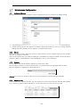
Alarm Configuration
4.3.1
Motion Detection
This setup menu allows users to set the camera’s motion detection alarm.
1. Check the “Enable” box. If unchecked, the camera will not send out any motion-based triggers, even if
there is motion in the video.
•
Alarm Holding Time
: Set the time between each event notification.
•
Trigger Alarm Out
: For cameras with an alarm output connection, check the box for the camera
to trigger the alarm output.
•
Trigger SD Snap
: Check the box to send a screenshot to the SD card when motion is detected.
•
Trigger SD Recording
: Check the box to send a video recording to the SD card when motion is
detected.
•
Trigger E-mail
: Check the box to set out an e-mail notification when motion is detected. Enter the
e-mail addresses to receive the notification. To send the e-mail to more than one e-mail address,
separate the accounts with a comma. Check the box next to “Attach Picture” to include a screenshot
of the event. Enter the e-mail subject and any notes, if needed, in the content field. The sending e-
mail address must be set in the E-mail configuration interface before e-mail notifications can work.
•
Trigger FTP
: Check the box to send a screenshot of the event to an FTP server. Enter the server’s
address in the field. See the FTP configuration section for more information.
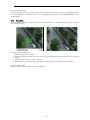
2. Click on the “Area of Sensitivity” tab and set the motion detection area and sensitivity.
• Move the “Sensitivity” scroll bar to set the sensitivity. The higher the sensitivity value, the motion
detection will be triggered based on smaller changes in the scene.
• Select “Add” and click “Draw Area”. Drag the mouse to draw the motion detection area on the
camera’s preview. Select “Stop Draw” when you are done. Check the “Erase” box and drag the
mouse to clear the motion detection area.
• Click “Save” to save the settings.
Page is loading ...
Page is loading ...
Page is loading ...
Page is loading ...
Page is loading ...
Page is loading ...
Page is loading ...
Page is loading ...
Page is loading ...
Page is loading ...
Page is loading ...
Page is loading ...
Page is loading ...
Page is loading ...
Page is loading ...
Page is loading ...
Page is loading ...
Page is loading ...
Page is loading ...
Page is loading ...
Page is loading ...
Page is loading ...
Page is loading ...
Page is loading ...
Page is loading ...
Page is loading ...
Page is loading ...
Page is loading ...
Page is loading ...
-
 1
1
-
 2
2
-
 3
3
-
 4
4
-
 5
5
-
 6
6
-
 7
7
-
 8
8
-
 9
9
-
 10
10
-
 11
11
-
 12
12
-
 13
13
-
 14
14
-
 15
15
-
 16
16
-
 17
17
-
 18
18
-
 19
19
-
 20
20
-
 21
21
-
 22
22
-
 23
23
-
 24
24
-
 25
25
-
 26
26
-
 27
27
-
 28
28
-
 29
29
-
 30
30
-
 31
31
-
 32
32
-
 33
33
-
 34
34
-
 35
35
-
 36
36
-
 37
37
-
 38
38
-
 39
39
-
 40
40
-
 41
41
-
 42
42
-
 43
43
-
 44
44
-
 45
45
-
 46
46
-
 47
47
-
 48
48
-
 49
49


Digital Watchdog DWC-MB94Wi28T, DWC-MB94Wi36T User manual
- Category
- Security cameras
- Type
- User manual
Ask a question and I''ll find the answer in the document
Finding information in a document is now easier with AI
Related papers
-
 Digital Watchdog DWC-MTT4Wi36 User manual
-
 Digital Watchdog DWC-MBT4Wi36 User manual
-
Digital Watchdog MegaPix DWC-MVT4WiA User manual
-
 Digital Watchdog Digital Watchdog DWC-MV95Wi28TW 5MP Vandal Dome 2.8mm User manual
-
Digital Watchdog MEGApix DWC-MF5Wi6TW User manual
-
 Digital Watchdog DWC-MV72Wi28ATW, DWC-MV72Wi4ATW User manual
-
 Digital Watchdog Digital Watchdog DW DWC-MVC8Wi28TW 8MP Vandal Dome 2.8mm User manual
-
Digital Watchdog DWC-MF4Wi6C6, DWC-MF4Wi6C1, DWC-MF4Wi6C2 User manual
-
 Digital Watchdog DW-BJC2P Installation guide
-
 Digital Watchdog DW-BJBLADE Installation guide


Other documents
-
Security Camera King IPOB-SB4IR28AD User manual
-
-
Vitek VTC-TNB3RVE User manual
-
-
COP-USA CD39IPZM-9545S2 Owner's manual
-
-
-
-
-
 TeleEye MS1120L User manual
