Page is loading ...

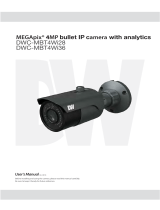
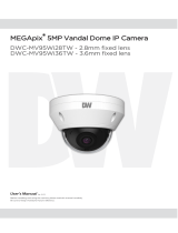
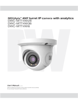
5MP IP Motorized Vandal Dome

Notes on Safety
This product is intended to be supplied by a Listed Power Unit, marked with 'Limited
Power Source', 'LPS' on unit, output rated minimum 12V/2 A or POE 48V/
350mA(depending on models), no more than 2000m altitude of operation and Tma=60
Deg.C.
As for the modes with PoE function, the function of the ITE being investigated to IEC
60950-1 standard is considered not likely to require connection to an Ethernet network
with outside plant routing, including campus environment and the ITE is to be
connected only to PoE networks without routing to the outside plant.
Do not attempt to disassemble the camera; in order to prevent electric shock, do not
remove screws or covers.
There are no user-serviceable parts inside. Please contact the nearest service center as
soon as possible if there is any failure.
Avoid from incorrect operation, shock vibration, heavy pressing which can cause damage
to product.
Do not use corrosive detergent to clean main body of the camera. If necessary, please use
soft dry cloth to wipe dirt; for hard contamination, use neutral detergent. Any cleanser for
high grade furniture is applicable.
Avoid aiming the camera directly towards extremely bright objects, such as, sun, as this
may damage the image sensor.
Please follow the instructions to install the camera. Do not reverse the camera, or the
reversing image will be received.
Do not operate it in case temperature, humidity and power supply are beyond the limited
stipulations.
Keep away from heat sources such as radiators, heat registers, stove, etc.
Do not expose the product to the direct airflow from an air conditioner.
This manual is for using and managing the product. We may reserve the rights of
amending the typographical errors, inconsistencies with the latest version, software
upgrades and product improvements, interpretation and modification. These changes will
be published in the latest version without special notification.
All pictures, charts, images in this manual are only for description and explanation of our
products. The ownerships of trademarks, logos and other intellectual properties related to
Microsoft, Apple and Google belong to the above-mentioned companies.
This manual is suitable for IR water-proof network cameras.

Disclaimer & Regulatory Information
Disclaimer
With regard to the product with internet access, the use of product shall be wholly at
your own risks. Our company shall be irresponsible for abnormal operation, privacy
leakage or other damages resulting from cyber attack, hacker attack, virus inspection, or
other internet security risks; however, Our company will provide timely technical support
if necessary.
Surveillance laws vary from country to country. Check all laws in your local region
before using this product for surveillance purposes. We shall not take the responsibility
for any consequences resulting from illegal operations.
FCC Marking
The products have be tested and found in compliance with the council FCC rules
and regulations part 15 subpart B. Operation of this product is subject the following two
conditions: (1) this device may not cause harmful interface, and (2) this device must
accept any interference received, including interference that may cause undesired
operation.
CE Marking
The products have been manufactured to comply with the following directives.
EMC Directive 2014/30/EU
RoHS Marking
The products have designed and manufactured in accordance with Directive EU RoHS
Directive 2011/65/EU and its amendment Directive EU 2015/863 on the restriction of the
use of certain hazardous substances in electrical and electronic equipment.

Table of Contents
1 Introduction ................................................................................................................... 1
2 Network Configuration ................................................................................................. 2
2.1 LAN ................................................................................................................... 2
2.1.1 Access through IP-Tool ............................................................................ 2
2.1.2 Directly Access through IE ....................................................................... 4
2.2 WAN .................................................................................................................. 5
3 Live View ........................................................................................................................ 8
4 Network Camera Configuration ................................................................................. 10
4.1 System Configuration ...................................................................................... 10
4.1.1 Basic Information ................................................................................... 10
4.1.2 Date and Time ........................................................................................ 10
4.1.3 Local Config ........................................................................................... 11
4.2 Image Configuration ........................................................................................ 11
4.2.1 Display Configuration ............................................................................ 11
4.2.2 Video Configuration ............................................................................... 13
4.2.3 OSD Configuration ................................................................................. 15
4.2.4 Video Mask ............................................................................................ 15
4.2.5 ROI Configuration .................................................................................. 16
4.2.6 Lens Control ........................................................................................... 17
4.3 Alarm Configuration ........................................................................................ 17
4.3.1 Motion Detection .................................................................................... 17
4.3.2 Alarm Server .......................................................................................... 19
4.4 Event Configuration (Optional) ....................................................................... 20
4.4.1 Object Removal ...................................................................................... 20
4.4.2 Exception ................................................................................................ 21
4.4.3 Line Crossing .......................................................................................... 22
4.4.4 Intrusion .................................................................................................. 24
4.5 Network Configuration .................................................................................... 25
4.5.1 TCP/IP .................................................................................................... 25
4.5.2 Port ......................................................................................................... 27
4.5.3 Server Configuration .............................................................................. 27
4.5.4 DDNS ..................................................................................................... 27
4.5.5 802.1x ..................................................................................................... 29
4.5.6 RTSP ....................................................................................................... 30
4.5.7 UPNP ...................................................................................................... 31
4.5.8 Email ...................................................................................................... 31
4.5.9 FTP ......................................................................................................... 32
4.5.10 HTTPS………………… ........................................................................ 32
4.5.11 P2P (Optional) ........................................................................................ 34
4.5.12 QoS ......................................................................................................... 34

Network Camera User Manual
4.6 Security Configuration ..................................................................................... 34
4.6.1 User Configuration ................................................................................. 34
4.6.2 Online User ............................................................................................. 36
4.6.3 Block and Allow Lists ............................................................................ 36
4.6.4 Security Management ............................................................................. 36
4.7 Maintenance Configuration.............................................................................. 37
4.7.1 Backup and Restore ................................................................................ 37
4.7.2 Reboot .................................................................................................... 38
4.7.3 Upgrade .................................................................................................. 38
4.7.4 Operation Log ......................................................................................... 38
5 Search ........................................................................................................................... 39
5.1 Image Search ................................................................................................... 39
5.2 Video Search .................................................................................................... 40
Appendix ................................................................................................................................ 42
Appendix 1 Q & A ................................................................................................................. 42
Appendix 2 Specifications .................................................................................................... 44

1
Network Camera User Manual
1 Introduction
This IP-CAMERA (short for IP-CAM) is designed for high performance CCTV solutions. It
adopts state of the art video processing chips, integrated with the most advanced technologies
(like video encoding and decoding technology) to make the image transmission more stable
and smooth. Moreover, the built-in WEB server of this series improves the performance of the
traditional surveillance system so that users can be easy to operate and monitor.
This product is widely used in banks, telecommunication systems, electricity power
departments, law systems, factories, storehouses, uptowns, etc. In addition, it is also an ideal
choice for surveillance sites with middle or high risks.
Main Features
ICR auto switch, true day/night
3D DNR, digital WDR
ROI coding
Support BLC, Defog, Anti-flicker
Support remote monitoring by smart phones with iOS or Android OS
Surveillance Application

2
Network Camera User Manual
2 Network Configuration
Connect IP-Cam via LAN or WAN. Here only take IE browser for example. The details are as
follows:
2.1 LAN
In LAN, there are two ways to access IP-Cam: 1. access through IP-Tool; 2. directly access
through IE browser.
2.1.1 Access through IP-Tool
Network connection:
① Make sure the PC and IP-Cam are connected to the local network and the IP-Tool is installed
in the PC from the CD.
② Double click the IP-Tool icon on the desktop to run this software as shown below:
③ Modify the IP address. The default IP address of this camera is 192.168.226.201. Click the
information of the camera listed in the above table to show the network information on the right
hand. Modify the IP address and gateway of the camera and make sure its network address is in
the same local network segment as the computer’s. Please modify the IP address of your device
according to the practical situation.

3
Network Camera User Manual
For example, the IP address of your computer is 192.168.1.4. So the IP address of the camera
shall be changed to 192.168.1.X. After modification, please enter the password of the
administrator and click the “Modify” button to modify the setting.
④ Double click the IP address and then the system will pop up the IE browser to connect
IP-CAM. Follow directions to download, install and run the Active X control.
Enter the username and password in the login window to log in.
The default password of the administrator is “123456”.
The default username is “admin”; the default password is “123456”.

4
Network Camera User Manual
The system will pop up the above-mentioned textbox to ask you to change the default password.
It is strongly recommended to change the default password for account security. If “Do not
show again” is checked, the textbox will not appear next time.
2.1.2 Directly Access through IE
The default network settings are as shown below:
IP address: 192.168.226.201
Subnet Mask: 255.255.255.0
Gateway: 192.168.226.1
HTTP: 80
Data port: 9008
Use the above default settings when logging in the camera for the first time. Directly connect
the camera to the computer through network cable.
① Manually set the IP address of the PC and the network segment should be as the same as
the default settings of the IP camera. Open the network and share center. Click “Local Area
Connection” to pop up the following window.
Select “Properties” and then select internet protocol according to the actual situation (for
example: IPv4). Next, click the “Properties” button to set the network of the PC.

5
Network Camera User Manual
② Open the IE browser and enter the default address of IP-CAM and confirm.
③ Follow directions to download and install the Active X control.
④ Enter the default username and password in the login window and then enter to view.
2.2 WAN
Access through the router or virtual server
① Make sure the camera is well connected via LAN and then log in the camera via LAN and
go to ConfigNetworkPort menu to set the port number.
Port Setup
② Go to Config NetworkTCP/IP menu to modify the IP address.

6
Network Camera User Manual
IP Setup
③ Go to the router’s management interface through IE browser to forward the IP address and
port of the camera in the “Virtual Server”.
Router Setup
④ Open the IE browser and enter its WAN IP and http port to access. (for example, if the http
port is changed to 81, please enter “192.198.1.201:81” in the address bar of web browser to
access).
Access through PPPoE dial-up
Network connection
Access the camera through PPPoE auto dial-up. The setting steps are as follow:

7
Network Camera User Manual
① Go to ConfigNetworkPort menu to set the port number.
② Go to Config NetworkTCP/IPPPPoE Config menu. Enable PPPoE and then enter
the user name and password from your internet service provider.
③ Go to Config NetworkDDNS menu. Before configuring the DDNS, please apply for a
domain name first. Please refer to DDNS configuration for detail information.
④ Open the IE browser and enter the domain name and http port to access.
Access through static IP
Network connection
The setting steps are as follow:
① Go to ConfigNetworkPort menu to set the port number.
② Go to Config NetworkTCP/IP menu to set the IP address. Check “Use the following IP
address” and then enter the static IP address and other parameters.
③ Open the IE browser and enter its WAN IP and http port to access.

8
Network Camera User Manual
3 Live View
After logging in, the following window will be shown.
The following table is the instructions of the icons on the live view interface.
Icon
Description
Icon
Description
Original size
Zoom out
Fit correct scale
Abnormal clarity indicator
Auto (fill the window)
Scene change indicator
Full screen
Line crossing indicator
Start/stop live view
Object removal indicator
Enable/disable audio (only
available for some
models)
Intrusion indicator
Snapshot
Motion alarm indicator
Start/stop local recording
AZ control (only available for the
model with motorized zoom lens )
Zoom in

9
Network Camera User Manual
Those smart alarm indicators will flash only when the camera supports those functions
and the corresponding events are enabled.
In full screen mode, double click on the mouse to exit or press the ESC key on the keyboard.
Click AZ control button to show AZ control panel. The descriptions of the control panel are as
follows:
Icon
Description
Icon
Description
Zoom -
Zoom +
Focus -
Focus +
One key focus (used when image is out of focus after manual adjustment

10
Network Camera User Manual
4 Network Camera Configuration
In the Webcam client, choose “Config” to go to the configuration interface.
Note: Wherever applicable, click the “Save” button to save the settings.
4.1 System Configuration
4.1.1 Basic Information
In the “Basic Information” interface, the system information of the device is listed.
Some versions may support device ID and QR code. Having been enabled P2P (see Network
Configuration-P2P), the network camera can be quickly added to mobile surveillance client,
by scanning the QR code or entering device ID.
4.1.2 Date and Time
Go to ConfigSystemDate and Time. Please refer to the following interface.

11
Network Camera User Manual
Select the time zone and DST as desired.
Click the “Date and Time” tab to set the time mode.
4.1.3 Local Config
Go to ConfigSystem Local Config to set up the storage path of captured pictures and
recorded videos on the local PC. There is also an option to enable or disable the bitrate
display in the recorded files.
For the model with built-in MIC, there is also an option to enable or disable audio recording.
4.2 Image Configuration
Image Configuration includes Display, Video/Audio, OSD, Video Mask and ROI Config.
4.2.1 Display Configuration
Go to ImageDisplay interface as shown below. The image’s brightness, contrast, hue and
saturation and so on for common, day and night mode can be set up separately. The image effect
can be quickly seen by switching the configuration file.

12
Network Camera User Manual
Brightness: Set the brightness level of the camera’s image.
Contrast: Set the color difference between the brightest and darkest parts.
Hue: Set the total color degree of the image.
Saturation: Set the degree of color purity. The purer the color is, the brighter the image is.
WDR: WDR can adjust the camera to provide a better image when there are both very bright
and very dark areas simultaneously in the field of the view by lowering the brightness of the
bright area and increasing the brightness of the dark area. Recording will be stopped for a few
seconds while the mode is changing from non-WDR to WDR mode.
Sharpness: Set the resolution level of the image plane and the sharpness level of the image
edge.
Noise Reduction: Decrease the noise and make the image more thorough. Increasing the
value will make the noise reduction effect better but it will reduce the image resolution.
Defog: Activating this function and setting an appropriate value as needed in foggy, dusty,
smoggy or rainy environment to get clear images.
Backlight Compensation:
Off: disables the backlight compensation function. It is the default mode.
HLC: lowers the brightness of the entire image by suppressing the brightness of the
image’s bright area and reducing the size of the halo area.
BLC: If enabled, the auto exposure will activate according to the scene so that the object
of the image in the darkest area will be seen clearly.
Antiflicker:

13
Network Camera User Manual
Off: disables the anti-flicker function. This is used mostly in outdoor installations.
50Hz: reduces flicker in 50Hz lighting conditions.
60Hz: reduces flicker in 60Hz lighting conditions.
White Balance: Adjust the color temperature according to the environment automatically.
Frequency: 50Hz and 60Hz can be optional.
Day/night Mode: Please choose the mode as needed.
Sensitivity: High, middle and low can be selected for switching back and forth from day to
night modes.
Infrared Mode: Choose “ON”, “OFF” and “Auto” (Some models may not support the
infrared mode).
Exposure Mode: Choose “Auto” or “Manual”. If manual is chosen, the digital shutter speed
can be adjusted.
Image Mirror: Turn the current video image horizontally.
Image Flip: Turn the current video image vertically.
Schedule Settings of Image Parameters:
Click the “Schedule” tab as shown below.
Set full time schedule for common, day, night mode and specified time schedule for day and
night. Choose “Timing” in the drop-down box of schedule as shown below.
Drag “ ” icons to set the time of day and night. Blue means day time and blank means night
time. If the current mode of camera parameters is set to schedule, the image configuration
mode will automatically switch between day and night according to the schedule.
4.2.2 Video Configuration
Go to ImageVideo interface as shown below. In this interface, set the resolution, frame rate,
bitrate type, video quality and so on subject to the actual network condition.

14
Network Camera User Manual
Three video streams can be adjustable.
Resolution: The size of image.
Frame rate: The higher the frame rate, the video is smoother.
Bitrate type: CBR and VBR are optional. Bitrate is related to image quality. CBR means that
no matter how much change is seen in the video scene, the compression bitrate will be kept
constant. VBR means that the compression bitrate will be adjusted according to scene changes.
For example, for scenes that do not have much movement, the bitrate will be kept at a lower
value. This can help optimize the network bandwidth usage.
Bitrate: it can be adjusted when the mode is set to CBR. The higher the bitrate, the better the
image quality will be.
Video Quality: It can be adjusted when the mode is set to VBR. The higher the image quality,
the more bitrate will be required.
I Frame interval: It determines how many frames are allowed between a “group of pictures”.
When a new scene begins in a video, until that scene ends, the entire group of frames (or
pictures) can be considered as a group of pictures. If there is not much movement in the scene,
setting the value higher than the frame rate is fine, potentially resulting in less bandwidth
usage. However, if the value is set too high, and there is a high frequency of movement in the
video, there is a risk of frame skipping.
Video Compression: H264 and H265 are optional. If H.265 is chosen, make sure the client
system is able to decode H.265.
Profile: For H.264. Baseline, main and high profiles are selectable.
Send Snapshot: How many snapshots to generate for an event.
Video encode slice split: If this function is enabled, more fluent image can be gotten even
though using the low-performance PC.
Watermark: When playing back the local recorded video in the search interface, the
watermark can be displayed. To enable it, check the watermark box and enter the watermark
text.
For the model with built-in MIC, audio encoding and type can be set. Click the “Audio” tab to
go to the interface as shown below.

15
Network Camera User Manual
Audio Encoding: G711A and G711U are selectable.
Audio Type: MIC.
4.2.3 OSD Configuration
Go to ImageOSD interface as shown below.
Set time stamp, device name and OSD content here. After enabling the corresponding display
and entering the content, drag them to change their position. Then click the “Save” button to
save the settings.
4.2.4 Video Mask
Go to ImageVideo Mask interface as shown below. A maximum of 4 zones can be set up.
To set up video mask:
1. Enable video mask.
2. Click the “Draw Area” button and then drag the mouse to draw the video mask area.
3. Click the “Save” button to save the settings.
4. Return to the live to verify that the area have been drawn as shown as blocked out in the
image.
/