Page is loading ...

IS-16226-US
We’re here to help 866-558-5706
Hrs: M-F 9am to 5pm EST
CAUTION
WHEN INSTALLING KICHLER® LANDSCAPE LIGHTING (LINE VOLTAGE OR LOW VOLTAGE), CARE SHOULD
BE TAKEN TO KEEP CLEAR OF POTENTIALLY COMBUSTIBLE MATERIALS.
TO ALLOW FOR PROPER OPERATION AND MAXIMUM LIGHT OUTPUT, BE SURE TO
REMOVE LEAVES, PINE NEEDLES, GRASS CLIPPINGS, MULCH, OR ANY DEBRIS THAT HAS ACCUMULATED
ON THE LIGHT BULB, LENS, OR BODY OF THE FIXTURE.
IMPORTANT SAFETY INSTRUCTIONS – READ ALL INSTRUCTIONS – SAVE THESE INSTRUCTIONS
For use with Kichler LED in-ground xtures 16226, 16227, 16228, 16229, 16230 and 16258
INSTALLATION:
• Excavation for conduit and conduit runs should be completed before proceeding.
• Installation must be done by a qualied electrician in accordance with local, state and national electric codes.
Installation:
1) Turn o power.
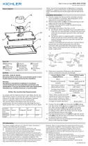
2) Remove decorative trim ring (A) by
removing four trim ring screws (B) using
2.5mm Allen hex wrench provided.
3) Remove xture assembly (C) from
plastic well assembly (D) by removing
two screws (E) using the 2.5mm hex
wrench provided. NOTE: It is not
necessary to open sealed xture
assembly for any part of the installation.
There are no adjustments or user
serviceable parts inside the unit.
4) Remove any packing material from well
housing or xture assembly.
5) NOTE: Well housing assembly must be
oriented correctly to ensure adjustable
beam tilt feature operates in the desired
directions.(See Figure 2 and 3.) At
desired location, dig hole approximately
3” larger in diameter and depth than the
housing. Top edge of housing should be
at or slightly above nish grade or to top
of concrete grade. Adjust by adding or
removing pea gravel or equivalent
drainage material.
6) Route conduit or supply through slots in
bottom of well housing.
7) Back-ll area between housing and hole
with pea gravel or equivalent drainage
material.
a. If installing in concrete, plastic
well housing should be secured
with reinforcing bars (rebar) (not
provided). Pour concrete to top
edge of well housing (D).
B – Trim Ring Screws
A – Trim Ring
E – Assembly Screws
F – Beam Tilt Adjustment Screw
C – Fixture Assembly
D – Well assembly
Figure 1

IS-16226-US
We’re here to help 866-558-5706
Hrs: M-F 9am to 5pm EST
Connect Black
Supply Wire to:
Connect White
Supply Wire to:
Connect Green
Ground Wire to:
Black White Ground
Insulated wire with
copper conductor
Insulated wire with
silver conductor
Insulated wire with
copper conductor
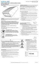
Figure 2
Figure 3
Beam Tilt
F – Beam Tilt
Adjustment Screw
E – Assembly Screws
Direction of Beam Tilt
Oval Aperture
F – Beam Tilt Adjustment Screw
Electrical connection:
8) Connect supply wires to xture (connectors
not provided). Reference chart for correct
connections and wire accordingly. NOTE:
Connections must be water-tight sealed in
accordance with local and national code(s).
Recommended: Wire gland seal for
3X#18 AWG SJOW xture wire (.32” [8mm] dia.)
and direct burial rated junction (not provided).
NOTE: Allow a minimum of 6” [15cm] clearance
from top edge of well housing for xture to seat
properly.
9) Replace xture assembly (C) into well housing
and reinstall screws (E) removed in step #3.
10) If desired, beam tilt angle may be adjusted up to
15° by rotating adjustment screw (F) at top of
xture assembly using the 3mm Allen hex
wrench provided. (See Figure 2 and 3.)
11) Reinstall decorative trim ring (A) and four trim
ring screws (B) using 2.5mm Allen hex wrench
provided.
Figure 4
IMPORTANT!!
ALLOW MINIMUM
6” [15cm] FIXTURE
CLEARANCE FROM
TOP EDGE OF WELL
PEA GRAVEL,
DRAINAGE
MATERIAL OR
CONCRETE
IMPORTANT!!
USE LISTED
WATERTIGHT
JUNCTION (NOT
PROVIDED)
PEA GRAVEL
OR OTHER
DRAINAGE
MATERIAL
FIXTURE ASSEMBLY
WELL ASSEMBLY
CONDUIT
(BY OTHERS)
15°
15°
/