Page is loading ...

Code 50122125 TS5110 ART 7 EN REV.0319
G2+ 2-wire installation
USER MANUAL
Soul kit
Art 7 monitor
TECHNOLOGY

SOUL S5110/ART 7 VIDEO DOOR ENTRY SYSTEM KIT 2
CONTENTS
Connection of an exit button ...........................................................................................................................31
Art 7/G2+ monitor...............................................................................................................................................9 to 24
Description ......................................................................................................................................................9
FA-G2+ power supply.................................................................................................................................................4
Descrip ......................................................................................................................................................5tion
Installation terminals ........................................................................................................................................6
Programming the proximity reader ...................................................................................................................8
Installation terminals ......................................................................................................................................10
Configuration switches...................................................................................................................................10
Door panel call screen....................................................................................................................................17
Communication screen ..................................................................................................................................18
Installation .....................................................................................................................................................10
Contents ....................................................................................................................................................................2
Descrip ......................................................................................................................................................4tion
Configuration switches.....................................................................................................................................7
Recordings menu ..................................................................................................................................22 to 24
One apartment with one access panel and one monitor .................................................................................. 52
Optional .....................................................................................................................................................................3
One apartment with two access panels and one monitor................................................................................. 52
Setting the audio level ......................................................................................................................................7
Recommendations.....................................................................................................................................................3
Intercom menu.......................................................................................................................................20 to 21
Cross sections and distances......................................................................................................................... 52
Main menu .....................................................................................................................................................11
System operation .......................................................................................................................................................3
Installation .......................................................................................................................................................6
Image and communication settings ................................................................................................................19
Two apartments with up to two access panels and up to four monitors in cascade ...........................................27
Four apartments with up to two access panels and up to four monitors in cascade...........................................28
Connection of a lock release...........................................................................................................................30
Soul panel............................................................................................................................................................5 to 8
Connection of an auxiliary device at the relay output .......................................................................................30
One apartment with up to two access panels and up to four monitors in distribution ......................................... 62
Installation .......................................................................................................................................................4
Settings menu........................................................................................................................................12 to 16
One apartment with up to two access panels and up to four monitors in cascade ............................................. 62
Wiring diagrams............................................................................................................................................... 5 to 92 2
Four apartments with up to access panels and up to four monitors in cascade ..........................................2four 9
Connection of an external camera ..................................................................................................................31
Special codes ..................................................................................................................................................32 to 34
Cleaning the door panel............................................................................................................................................35
Cleaning the monitor 3................................................................................................................................................ 5
Connection for an apartment door button........................................................................................................31
Compliance..............................................................................................................................................................36

3
SYSTEM OPERATION
RECOMMENDATIONS
- The wiring must run at least 40cm away from any other wiring.
-Always disconnect the power supply before making modifications to the device.
- Preferably use a Golmar cableRAP-GTWIN/HF (2x1mm²).
-Always follow the instructions contained in this manual.
- Check all connections before starting the device.
- The installation and handling of these devices must be carried out by authorised personnel.
SOU S5110/ART 7 VIDE ENTL O DOOR RY SYSTEM KIT
In systems with two access doors, the other door panel automatically disconnects; if another visitor attempts to call, a
number of telephone tones will indicate that the system is busy and LED on the door panel will illuminate.
Upon receiving the call, the image will appear on the screen of the master monitor (and slave 1, if it exists) without the
visitor knowing and icon displayed on the screen will blink green. To view the image from slave monitors 2 or 3,
press one of the hidden buttons (located above the raised dots for the visually impaired) of the monitor to display the
image. If the call is not answered within 45 seconds, door panel LED will turn off and the system will become free.
To open door or activate auxiliary output of the door panel, press the hidden button below the corresponding icon
displayed on the screen. A single press activates the lock release or auxiliary output for 3 seconds
, and LED on the door panel illuminates.
(with the possibility of
setting it to between 0.5 and 10 seconds see pp. 32-34),
Detailed operation of the monitor is described on pp. 11-24.
To make a call, the visitor needs to press the button for the apartment, an audible tone indicates that the call is being
made and LED on the door panel illuminates. At this moment, the apartment's monitor(s) receive(s) the call. If the
visitor presses the button for another apartment by mistake, the call can be cancelled by pressing the button for the
correct apartment.
The owner of the apartment can activate the lock release by holding the proximity key over the reader. If the proximity
key is held for three seconds, the auxiliary relay output will be activated.
To establish communication, press the hidden button below off-the-hook icon shown on the screen. Door panel
LED will illuminate. Communication will last for 90 seconds or until the hidden button below on-the-hook icon
shown on the screen is pressed. When communication has ended, door panel LED will turn off and the
system will become free.
12

4
FA-G2+ POWER SUPPLY
Description
B
D. Fastening tab on DIN rail.
A. On/off indicator light.
B. Protective current input cover.
C. Detail of current input terminals without protective
cover.
E. Installation terminals.
A
ED
BUS(M) BUS PL( )
Installation
Install the power supply in a dry, protected and ventilated location. Make sure that the vents are not obstructed.
Use a DIN 46277 rail for fastening (8 elements).
To prevent electric shock, do not remove the protective cover without first disconnecting the power supply. Replace
it once all connections have been made.
Connect the wires to the installation terminals following the instructions in the diagrams.
The fitting and handling of the power supply must be carried out by authorised personnel in the absence of
electrical current.
Note that current regulations stipulate that the power supply must be protected by a circuit breaker.
C
12240100
OUTPUT
NL
GOLMAR S.A. C/ Silici, 13 08940 - SPAIN
MADE IN CHINA
BUS 30V 2V 1.2A±
INPUT ~100-240V
0.8A 50-60Hz FA-G2+
PL
BUS BUS
SOU S5110/ART 7 VIDE ENTL O DOOR RY SYSTEM KIT

5
SOUL PANEL
Description
A
B
C
F
E
D
J
I
G
J
G
H H
B
C
D
L
M M
K M
Q
O
O
P
I
N
T
K
R
S
M. Do not overtighten the
fixing screws.
Wall fixing hole (x3).
F. Proximity card reader.
Q. Proximity reader connector.
S. Volume control potentiometer.
I. Call button(s).
H. .Colour camera
P. Cable grommet.
T. Proximity reader configuration button.
G. Speaker grill.
K. Front fixing screw.
J. Microphone hole.
L. Proximity reader.
O. Installation terminals.
N. Proximity reader gasket.
R. Configuration switches.
A. System status icons:
Communication established.
Lock release activated.
B. System status indicator lights.
D. Night viewing lighting.
E. Protective polycarbonate.
C. Ambient lighting sensor.
Call in progress.
System busy.
SOU S5110/ART 7 VIDE ENTL O DOOR RY SYSTEM KIT

6
SOUL PANEL
Installation
The door panel has been designed to withstand diverse environmental conditions. It is however advisable to take
extra precautions to prolong its service life, such as locating it in a covered area.
For correct installation: (locate the top of the door panel at a height of 1.65m).
3. Present the door panel to the wall, positioning the top at 1.65m. Pass the installation cables through the cable
grommet.
5 .. Connect the cables to the removable terminals following the instructions in the installation diagrams
For optimum image quality, avoid direct contact from light sources (sunshine, street lights, etc.).
1. Remove the metal front piece of the door panel by loosening the bottom screw with the Allen key supplied. On
the back of the front piece, you will find the button personalisation label.
2 .. Remove the screws that secure the proximity reader
4
.
. Drill three 6mm holes at the indicated points (M), see p. 5. Insert the plugs supplied and fix the door panel to the
wall using the screws supplied
Before replacing the proximity reader and closing the door panel, perform the necessary settings (proximity key
programming, audio level setting, etc.), as indicated throughout this manual. Make sure that the proximity
reader gasket is properly fitted.
Installation terminals (O)
For ease of installation, the installation terminals are removable and supplied in a separate bag. Once the
terminals are wired, place them in position.
BUS BUS CV- CV+ AP+
C NA GND CCTV AP-
ON
1 2 3 4
BUS BUS communications bus (non-polarised)., :
GND CCTV input for external analogue camera., :
AP AP remote activation button connection. Note: For correct
operation, the monitor's address 1 must be connected to
the Bus
+, -:
C, :NA potential-free relay output (maximum 6A/24V).
CV CV lock release output 12Vdc (maximum 270mA).-, +:
SOU S5110/ART 7 VIDE ENTL O DOOR RY SYSTEM KIT

7
SOUL ANELP
Configuration switches (R)
All switches are factory set to OFF.
Configuration changes should be made with the equipment turned off. If they are performed with the equipment
turned on, disconnect it for 10 seconds after any modification.
Note: Configuration switches for the SOUL/1, SOUL/2, and SOUL/4 with version V04 and next.
Switch 1 .and 2
Defines the door panel address.
Door panel 1
1apartment
* .Same value as setting them to ON-ON
2apartments
Switches and3 4.
2: the two bottom buttons call apartment 1,
the two top buttons call apartment 2.
Define the number of apartments:
4: .each button calls one apartment
1: all buttons call apartment 1.
4apartments
Setting the audio level
If the audio volume on the door panel after starting up the device is not adequate, use the volume control
potentiometer (S). This setting affects the communication and confirmation tone audio level.
BUS BUS CV- CV+ AP+
C NA GND CCTV AP-
ON
1 2 3 4
SOU S5110/ART 7 VIDE ENTL O DOOR RY SYSTEM KIT
S
Door panel 2
OFF-OFF
* -OFF OFF
O -OFFN
ON OFF- OFF ON-
ON
1 2 3 4
ON
1 2 3 4
ON
1 2 3 4
ON
1 2 3 4
ON
1 2 3 4
OFF-ON O -ONN
ON
1 2 3 4
ON
1 2 3 4
Door panel 3Door panel 4

8
SOUL ANELP
Programming the proximity reader (L)
To add user keys (up to 60) to the memory of the proximity reader, it is necessary to create a programming key and
a user registration key. In order to facilitate identification, we recommend using the yellow key to programme
and the blue key to register users. Use the grey ones as user keys.
Creating programming and registration keys.
NOT .E: This process completely deletes the memory of the proximity reader
Press the programming button of the proximity reader (T): the door panel will emit six short tones. Within ten
seconds, hold the programming key up until the door panel emits a short confirmation tone and then hold the
user registration key up until the door panel emits a long confirmation tone. If no key is held up within ten
seconds of pressing the programming button, the door panel will emit a long tone and the memory will have
been completely deleted.
Once the programming and registration keys have been created, the addition and deletion of user keys can be
done with the door panel closed.
Deleting all user keys.
Adding user keys.
Make sure that the device is powered and the reader is connected to the door panel (Q).
Hold the registration key up to the reader: the door panel will emit four short tones. One by one, hold up the user
keys that you wish to add until a short tone is emitted for each key added. Ten seconds after adding the last
key, the door panel will emit a long tone to confirm completion of the process.
Hold the programming key up to the reader: the door panel will emit four short tones. Hold up one added user
key (registered in the previous step) until the door panel emits a long tone to confirm the deletion of all user
keys. After ten seconds, if the registration key has not been held up, the door panel will emit a long tone to
confirm completion of the process.
BUS BUS CV- CV+ AP+
C NA GND CCTV AP-
ON
1 2 3 4
SOU S5110/ART 7 VIDE ENTL O DOOR RY SYSTEM KIT
T

9
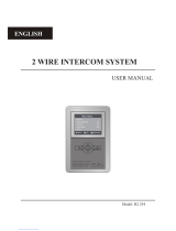
ART MONITOR7/G2+
Description
SOU S5110/ART 7 VIDE ENTL O DOOR RY SYSTEM KIT
Power on indicator.
Auxiliary relay activated.
A. Speaker.
Do not disturb.
B. Notification icons:
Door opening.
New image/video.
C. Hidden button indicator LEDs :
To access the main menu (monitor in standby), press
either of the 2 hidden buttons with indicator LEDs
illuminated, located above the raised dots for the
visually impaired (see p. 11).
In call/communication: an LED shows the location of
each of the hidden buttons.
The function of each hidden button is shown on the
monitor screen with an icon located just above
each button (see pp. 11-24).
F. Microphone.
Above this raised dot is the hidden 'Start/end
communication' button.
In standby:
In call:
Above this raised dot is the hidden 'Door opening'
button.
E. 7” TFT colour screen.
I. Configuration switches.
J. Installation terminals.
Above the raised dots for the visually impaired / are
the hidden buttons that access the main menu.
D. .Raised dots for the visually impaired
G. Micro SD card slot (not included).
Type: MicroSD Class 10 from 4GB to 128GB.
H. Wall mounting connector fixing (x4).
A
E
B
C
D
F
G
SA
GND
HZ
HZ
BUS
IN
OFF = 0 | ON = 1
DIP 1 to 5
DIP 8
Monitor address
End of line resistor
DIP 6,7
00 - Master
10 - Slave 1
01 - Slave 2
11 - Slave 3 BUS
OUT
H
I
J
H
H
H
J
SA
GND
HZ
HZ
BUS
IN
ON
1 2 3 4 5 6 7 8
*
*
12210701 V02Product Version:
MONITOR 7” ART 7/G2+
GOLMAR S.A.
C/ Silici, 13
08940 - SPAIN
WARNING
TO PREVENT FIRE OR ELECTRIC
SHOCK, DO NOT EXPOSE THIS
DEVICE TO RAIN OR MOISTURE
TO PREVENT ELECTRIC SHOCK,
CAUTION
DO NOT REMOVE COVER. NO
USER SERVICEABLE PARTS
INSIDE. REFER SERVICING TO
QUALIFIED SERVICE PERSONNEL.
MADE IN CHINA
BUS
OUT
Hidden button
pressing area

10
Installation
Avoid dusty or smoky environments or locations near sources of heat.
For proper installation, use the template supplied with the product.
1. Position the top of the template at a height of 1.65m.
2. If you are going to use an embedding box to pass the wiring through, make sure that it is in line with the holes
corresponding to the box model chosen and fix the connector. If you prefer to fix the connector directly to the
wall, make four 6mm holes at the points indicated (A), insert the wall plugs supplied and screw in the connector.
4. Connect the removable terminals to the monitor and place the monitor in front of the connector, making sure the
fixings line up. Move the monitor downwards to secure it.
3.
.
Pass the installation wires through the middle hole and connect them to the removable terminals as shown in the
wiring diagrams. Before connecting the removable terminals to the monitor, configure the switch as indicated
below
ART 7/G + M2 ONITOR
Installation terminals ( )J
For ease of installation, the installation terminals are removable and supplied in a separate bag. Once the
terminals are wired, place them in position.
Connect only on the master monitor. The signal received is then
transmitted to the slave monitors in the same apartment through the
.BUS
SA GND Auxiliary call repeater output (max 50mA/12V), relay
SAR-12/24.
, :
HZ HZ Apartment front door button input:, :
BUS OUT Communication bus output to additional monitor (non-polarised).:
BUS Communication bus input to monitor (non-polarised).IN:
SA
GND
HZ
HZ
ON
1 2 3 4 5 6 7 8
Configuration switches ( )I
Switches 1 to 5.
These assign the address of the corresponding monitor to its call button on the door panel. Switches to 5 must
remain in the OFF position.
4
These define whether the monitor is master or slave. Each apartment must have one master monitor, and only
one.
Switches 6 and 7.
Switch 8.
This activates the end-of-line resistance in the ON position. Activate it in monitors where the bus cable ends.
Deactivate it only in intermediate monitors.
Slave 1 Slave 2 Slave 3Master
ON
1 2 3 4 5 6 7 8
ON
1 2 3 4 5 6 7 8
ON
1 2 3 4 5 6 7 8
ON
1 2 3 4 5 6 7 8
SOU S5110/ART 7 VIDE ENTL O DOOR RY SYSTEM KIT
BUS
OUT
BUS
IN
Apartment 1 Apartment 2 Apartment 3 Apartment 4
ON
1 2 3 4 5 6 7 8
ON
1 2 3 4 5 6 7 8
ON
1 2 3 4 5 6 7 8
ON
1 2 3 4 5 6 7 8

11
MONITOR ART 7/G2+
Main menu
SOU S5110/ART 7 VIDE ENTL O DOOR RY SYSTEM KIT
If the device is in standby (screen switched off), to access the main menu, press either of the 2 hidden buttons with
indicator LEDs illuminated (located above the raised dots for the visually impaired) on the monitor. Then
press the hidden button located just below the corresponding icon. The device will return to standby mode after
30 seconds without activity.
/
"
Press the hidden button below icon to display the image from the door panels and cameras
connected to the system. Note: This enables the door panel camera to be changed, the audio on
the corresponding door panel to be activated and the door to be opened (see p. 17).
Press the hidden button below icon to access the menu of the intercom between other monitors in
the same apartment or other apartments (see pp. 20-21).
Press the hidden button below icon to display the list of images recorded in the memory of the
device. If a MicroSD card is inserted in the monitor, images/videos will be recorded on the
MicroSD card (see pp. 22-24).
Press the hidden button below icon to make changes to the system settings (see pp. 12-16).
Indicates that the inserted Micro SD card must be formatted from the monitor. Access this
function by pressing the hidden button below icon to access the Micro SD card format
menu, then press the hidden button below icon to start formatting the Micro SD card. To
return to the main menu, press the hidden button below icon . To exit without formatting,
press the hidden button below icon .
09:27
01 7 9-0 -201
There are no images/videos pending viewing.
There are images/videos pending viewing.
Hidden button
pressing area
LED indicators
Raised dots for the
visually impaired
No function.
Press the hidden button below icon to enable disable
the 'Do not disturb' function: If the monitor is in 'Do not disturb' mode, the ringtone on the
monitor does not sound when a call is received and the notification icon will illuminate.
for 3 seconds and for 1 second to

12
ART MONITOR7/G2+
Settings menu
SOU S5110/ART 7 VIDE ENTL O DOOR RY SYSTEM KIT
Returning to the main menu: Press the hidden button below icon to return to the main menu.
Setting the monitor's date and time, as well as the presentation format: Press the hidden button below
icon to access the settings screen. Go to the option to be modified by pressing the hidden
buttons below corresponding icons / , then select the option to modify by pressing the hidden
button below icon .
07 00 AM PM/
31 08 2019
DD MM YY/ /
Continued overleaf

13
ART MONITOR7/G2+
Selecting the melody and call volume: Press the hidden button below icon to access the settings
screen. In order to identify the origin of the calls when you are not in front of the monitor, select
different melodies and the desired call volume. Go to the option to be modified by pressing the
hidden buttons below corresponding icons / , then press the hidden buttons below
corresponding icons / to select the melodies and desired call volume. Press the hidden
button below icon to validate the changes made and return to the settings menu.
Important: Door panels and have no use in house applications with SOUL door panels.
Settings menu
SOU S5110/ART 7 VIDE ENTL O DOOR RY SYSTEM KIT
S
.
elect the field to modify by pressing the hidden buttons below corresponding icons / , then press
the hidden buttons below corresponding icons / to adjust the value/format. Validate the
changes made by pressing the hidden button with icon . After setting the desired values, press
the hidden button below icon to return to the settings menu
Continued from previous page.
07 00 AM PM/
31 08 2019
DD MM YY/ /
105
205 03
01
02
305
405
34

14
ART MONITOR7/G2+
Settings menu
SOU S5110/ART 7 VIDE ENTL O DOOR RY SYSTEM KIT
Automatically deleting images/videos, image recording mode, internal memory and Micro SD card: Press
the hidden button below icon to access the settings screen. In some countries, the law does not
permit the storage of images or videos for more than 30 days after recording. The automatic deletion
function performs this task for you. You can disable this function if your country's legislation does not
require it, or under your responsibility.
If you have not inserted a Micro SD card into your monitor, only still images can be recorded in the
internal memory of the monitor (up to 100). If you have inserted one, the images and videos will
always be recorded on the card, and the images in the internal memory cannot be displayed until
you copy them to the card.
Press the hidden button below icon to return to the settings menu.
From this menu, you can select the image recording mode, delete contents, copy from the internal
memory to the Micro SD card and format the card. Any of these actions (copy/delete) will require
confirmation.
In some countries, the law does not permit the storage of images or videos for more than 30 days after
recording. The automatic deletion function performs this task for you. You can disable this function if
your country's legislation does not require it, or under your responsibility. To disable this function, go
to the option to be modified by pressing the hidden buttons below corresponding icons / ,
then press the hidden button below icon to enable/disable the automatic deletion function. Press
the hidden button below icon to return to the settings menu.
If you have inserted a Micro SD card into the monitor, you can copy previously recorded still
images on the monitor to the new Micro SD card and then delete the still images from the
internal memory of the monitor. Press the hidden button below icon to return to the settings
menu.
To copy the still images recorded on the monitor to the Micro SD card, go to the option with icon
by pressing the hidden buttons below corresponding icons / . Press the hidden button
below icon to access the card format menu, then press the hidden button below icon to
perform this function.
To delete the still images recorded in the internal memory of the monitor, go to the option with icon
by pressing the hidden buttons below corresponding icons / . Press the hidden button below
icon to access the card format menu, then press the hidden button below icon to perform this
function.Continúa
To select the image recording mode during the reception of a call: still image video and without
recording , go to the desired option by pressing the hidden buttons below corresponding icons
/ , then press the hidden button below icon to select the recording mode. To return to the
settings menu, press the hidden button below icon .

15
ART MONITOR7/G2+
SOU S5110/ART 7 VIDE ENTL O DOOR RY SYSTEM KIT
Settings menu
'Do not disturb' and enable/disable intercom settings mode: Press the hidden button below icon to
access the settings screen. You can set a period of time during which the monitor will not sound
when receiving calls. To do so, enable the timer function and choose the time period. From the
main menu, you can enable and disable the 'Do not disturb' function regardless of the timer status.
f you wish be contacted from another monitor in another apartment, you the intercom
function between apartments .
to must enable
21 0700 00
07 00 07 00
If you have inserted a Micro SD card into the monitor, you can delete the still images and videos
recorded on the Micro SD card. The monitor has the option to format the Micro SD card. Press
the hidden button below icon to return to the settings menu.
To delete the still images recorded on the Micro SD card, go to the option with icon by pressing
the hidden buttons below corresponding icons / . Press the hidden button below icon
to access the still image deletion menu, then press the hidden button below icon to
perform this function.
To delete the videos recorded on the Micro SD card, go to the option with icon by pressing the
hidden buttons below corresponding icons / . Press the hidden button below icon to
access the video deletion menu, then press the hidden button below icon to perform this
function.
To format the Micro SD card, go to the option with icon by pressing the hidden buttons below
corresponding icons / . Press the hidden button below icon to access the card format
menu, then press the hidden button below icon to perform this function.
To set a period of time during which the monitor will not sound when receiving calls, go to the option
with icon by pressing the hidden buttons below corresponding icons / , select the option
to be modified by pressing the hidden button below icon , then select the field to be modified by
pressing corresponding buttons / and modify the desired period of time by pressing the
hidden buttons below corresponding icons / , and finally validate the changes made by
pressing the hidden button below icon . Press the hidden button below icon to return to the
settings menu.
Continued from previous page.
Continúa

16
ART MONITOR7/G2+
SOU S5110/ART 7 VIDE ENTL O DOOR RY SYSTEM KIT
Settings menu
It enables the monitor to be restored to factory settings, such as melodies, call volume, etc.
The 'About' screen provides information about the monitor, such as the software version, address
and whether it is master or slave (M, S1, S2 or S3).
Press the hidden button below icon to return to the settings menu.
It enables updated versions of the manual to be downloaded to a mobile or tablet, for which it is
necessary to have a QR code scanner app installed.
To activate and set a period of time for the automatic opening of door (after 3 seconds of
receiving a call from the door panel), go to the option with icon by pressing the hidden
buttons below corresponding icons / and select the automatic door opening function
activation option by pressing the hidden button below icon . Then, if you wish to set a
period of time for opening the door, select the field to be modified by pressing corresponding
buttons / , modify the desired period of time by pressing the hidden buttons below
corresponding icons / and validate the changes made by pressing the hidden button
below icon . Press the hidden button below icon to return to the settings menu.
.(This function is disabled by default. To enable it, see pp. 32-34)
1
To enable/disable the intercom function between apartments, go to the option with icon by
pressing the hidden buttons below corresponding icons / . Then press the hidden button
below icon to enable/disable this function. Press the hidden button below icon to return
to the settings menu. (This function is disabled by default).
To restore the monitor to factory settings, press the hidden button below icon to access the
factory reset menu, then press the hidden button below icon to perform this function. Press
the hidden button below icon to return to the 'About' screen. Press the hidden button below
icon to return to the settings menu.
Press the hidden button below icon to return to the settings menu.
FW
0 2 /0 M
1.02
Continued from previous page.

17
ART MONITOR7/G2+
Door panel call screen
SOU S5110/ART 7 VIDE ENTL O DOOR RY SYSTEM KIT
This screen is displayed when you receive a call or when you press the hidden button below icon of the main
menu. During a call, icon displayed on the screen will blink green (during the call process). In the top centre
of the screen, the date and time are shown and, on the right, the source of the image is displayed (door panel 1,
door panel 2, camera 1 or camera 2). The call has a duration of 45 seconds.
Press the hidden button below icon to cancel the current call or display and return to the main
menu.
Press the hidden button below icon / to start or end audio communication with the
door panel displayed respectively. Communication has a maximum duration of
90 seconds. Once communication has ended, the screen will turn off" .
Press the hidden button below icon to change the source of the image as long as the system has
more than one door panel or has an external camera connected and display has been activated
(see pp. 32-34). It is possible to make the change during display, call and communication
processes.
A few seconds after receiving a call, it automatically takes a photograph. In the top left of the screen,
icon is displayed and indicator will illuminate. Press the hidden button below icon to
take a picture.
If a Micro SD card is inserted, a 15-second video automatically starts recording a few seconds after
receiving the call. In the top left of the screen, icon is displayed and indicator will illuminate
(see p. 14 to configure video recording mode). Then a short 1-second press on the hidden button
below icon will take a photograph or a long 2-second press will record a video.
0 -0 -21 7 019 11:17:10
1
12
Press the hidden button below icon to activate the lock release (or device connected to the CV
output of the door panel) for 3 seconds(factory setting, programmable by the installer; see pp. 32-34 .
During activation, indicator will illuminate.
)
Press the hidden button below icon to activate the lock release (or device connected to the relay
output of the door panel) for 3 seconds ( )factory setting, programmable by the installer; see pp. 32-34 .
During activation, indicator will illuminate.
1
2
1
2

18
ART MONITOR7/G2+
Communication screen
SOU S5110/ART 7 VIDE ENTL O DOOR RY SYSTEM KIT
This screen is displayed during a communication process. In the top centre of the screen, the date and time are
shown and, on the right, the source of the image is displayed (door panel 1, door panel 2, camera 1 or camera 2).
Press the hidden button below icon / to start or end audio communication with the
door panel displayed respectively. Communication has a maximum duration of 90
seconds. Once communication has ended, the screen will turn off.
Press the hidden button below icon to change the source of the image as long as the system has
more than one door panel or has an external camera connected and display has been activated
(see pp. 32-34). This enables the door panel camera to be changed, the audio of the
corresponding door panel to be activated and the door to be opened.
Press the hidden button below icon to take a picture. In the top left of the screen, icon is
displayed.
Note: If a Micro SD card is inserted, a 15-second video automatically starts recording a few seconds
after . In the top left of the screen, icon is displayed and indicator will
illuminate (see p. 14 to configure video recording mode). Then a short 1-second press on the
hidden button below icon will take a photograph or a long 2-second press will record a video.
receiving the call
Press the hidden button below icon to access the image and monitor in communication volume
settings menu. Go to the option to be modified by pressing the hidden buttons below
corresponding icons / , change to the desired level by pressing the hidden buttons below
corresponding icons / and validate the changes made by pressing the hidden button below
icon , (see p. 19).
1 2
0 -0 -21 7 019 11:17:10
1
Press the hidden button below icon to activate the lock release (or device connected to the CV
output of the door panel) for 3 seconds(factory setting, programmable by the installer; see pp. 32-34 .
During activation, indicator will illuminate.
)
Press the hidden button below icon to activate the lock release (or device connected to the relay
output of the door panel) for 3 seconds ( )factory setting, programmable by the installer; see pp. 32-34 .
During activation, indicator will illuminate.
1
2
1
2

19
Image and communication settings
SOU S5110/ART 7 VIDE ENTL O DOOR RY SYSTEM KIT
During a communication process, press the hidden button below icon to access the image and monitor in
communication volume settings menu
The following settings menu will then appear (brightness, contrast, colour and monitor in communication volume). Go to the
option to be modified by pressing the hidden buttons below icons / and change to the desired level by pressing
the hidden buttons below corresponding icons / . To exit the screen settings and monitor volume menu and
validate the changes made, press the button below icon .
0 -0 -21 7 019 11:17:10
1
ART MONITOR7/G2+
1 2
0 -0 -21 7 019 11:17:10
1

20
Intercom menu
A
.
ccess the intercom menu as described on p. 11. From this menu, you can contact another monitor(s) in your
apartment (internal intercom) or other apartments (external intercom). For external intercom, the monitor called
must have its intercom function enabled from the 'Do not disturb' menu (factory setting: bled)disa
If during an intercom process with another monitor a call is received from the door panel, the intercom process will
be terminated, and the door panel call will be received on the corresponding monitor.
Select option or to perform an internal or external intercom call.
Use icon to return to the main menu.
SOU S5110/ART 7 VIDE ENTL O DOOR RY SYSTEM KIT
S1
M S2
S3
0 0 2
To make an internal intercom call (to another monitor(s) in the same apartment), go to the option with
icon by pressing the hidden buttons below corresponding icons / and press the hidden button
below icon to access the monitor selection menu (in the same apartment). Note: You will find information
about the monitor itself with the address, Master, Slave 1 to Slave 3 of the monitor in the 'About' menu,
(see p. 16).
Continued overleaf
Then press the hidden buttons below icons / to select the monitor to call and press the hidden button
below icon to make the call. The monitor making the call will play a confirmation melody and indicate
with a blink the monitor called. To cancel the call, press the hidden button below icon . Press the
hidden button below icon to return to the intercom menu. The monitor receiving the call will play a
confirmation melody showing on screen with a blink the monitor making the call. Press the button below
icon to establish communication and press the hidden button below icon to end communication.
ART MONITOR7/G2+
S1
M S2
S3
002
/