Page is loading ...

SkyView SE, SkyView Classic,
SkyView Touch, SkyView HDX
AF-5000 Touch Displays (OS:5),
AF-6000 Series
Autopilot In-Flight Tuning Guide
For Skyview Software Version 16.4
and AFS Software Version Vx16.10
102064-000
Revision E
1/17/2023
Copyright © 2023 by Dynon Avionics, Inc.
Dynon Avionics grants third parties' permission to print this document

Contact Information
Dynon Avionics, Inc.
19825 141st Place NE
Woodinville, WA 98072
Technical Support
Phone: +1 (425) 224-6736, 8:00 AM – 5:00 PM (Pacific Time) Monday – Friday
Email: support@dynon.com
Sales
Phone: +1 (425) 650-1269, 8:00 AM – 5:00 PM (Pacific Time) Monday – Friday
Email: [email protected]
Find Us on the Web
dynon.com – Dynon homepage
dynon.com/docs – Product documentation
dynon.com/download – Software updates for products
dynon.com/support – Support resources
dynon.com/register – Register your Dynon Avionics product
shop.dynon.com – Dynon’s secure online store
Stay in Touch
dynon.com/newsletter – Sign up to receive Dynon’s newsletter
forum.flydynon.com – Dynon-hosted forum for customers and pilots
preflight.dynon.com – Dynon’s blog
facebook.com/dynonavionics
instagram.com/dynonavionics
twitter.com/dynon
Videos and Training
youtube.com/DynonAvionics – Training, events, and other videos on YouTube
Copyright
©2023 Dynon Avionics, Inc. All rights reserved. No part of this manual may be reproduced, copied, transmitted, disseminated, or stored in any
storage medium, for any purpose without the express written permission of Dynon Avionics. Dynon Avionics hereby grants permission to
download a single copy of this manual and of any revision to this manual onto a hard drive or other electronic storage medium to be viewed for
personal use, provided that such electronic or printed copy of this manual or revision must contain the complete text of this copyright notice and
provided further that any unauthorized commercial distribution of this manual or any revision hereto is strictly prohibited.
Information in this document is subject to change without notice. Dynon Avionics reserves the right to change or improve its products and to
make changes in the content without obligation to notify any person or organization of such changes. Visit the Dynon Avionics website
(dynon.com) for current updates and supplemental information concerning the use and operation of this and other Dynon Avionics products.

DOCUMENT NAME
DOCUMENT #
REV
DATE
PAGE
Autopilot In-Flight Tuning Guide
102064-000
Revision E
1/17/2023
ii
For Skyview Software Version 16.4and AFS Software Version Vx16.10
Revision History
REV
DATE
APPROVED
DESCRIPTION OF CHANGE
A
6/1/2013
LED
Initial release
B
3/1/2014
LED
Updated for SV v10.0.
• Added BANK ANGLE LIMIT
• Mention of SV-AP-PANEL only active in EXPERT mode
C
12/1/2016
ECO 246525
• Changed default value of VSI Gain
D
9/8/2022
ECO 380245
Reformatted document.
• Updated flow charts.
• Added tables with default values, and variable description.
• Created new step-by-step procedures for autopilot tuning methods.
• Added yaw damper information.
• Updated Section 2 to add additional detail and update criteria for
autopilot testing performed prior to in-flight tuning.
• Added flight director check for heading mode
• Updated VOR intercept distance
Updated for SV v16.4.
• Added lost motion compensation instructions
• Added AFS-specific parameters
E
1/17/2023
ECO 381452
• Corrected Rudder Gain default value in Table 6: Yaw Damper Parameters.

DOCUMENT NAME
DOCUMENT #
REV
DATE
PAGE
Autopilot In-Flight Tuning Guide
102064-000
Revision E
1/17/2023
iii
For Skyview Software Version 16.4and AFS Software Version Vx16.10
Table of Contents
1 Introduction .................................................................................................. 4
1.1 Using this Manual ......................................................................................................... 4
1.2 Document Iconography ................................................................................................ 4
1.3 Reference Documents .................................................................................................. 4
1.4 Glossary ....................................................................................................................... 4
2 Important Steps Prior to In-Flight Tuning ................................................. 5
2.1 Servo Calibration .......................................................................................................... 5
2.2 Auto-Trim Calibration ................................................................................................... 5
2.3 Servo to Flight Control Coupling Check ........................................................................ 5
2.4 Autopilot Disconnect Test ............................................................................................. 6
2.5 Magnetometer Calibration ............................................................................................ 6
2.6 ADAHRS Zero-Pressure Calibration ............................................................................. 6
2.7 Broken Shear Screw Test ............................................................................................ 6
3 Roll Axis Tuning ........................................................................................... 7
3.1 Tuning Procedures ....................................................................................................... 7
3.2 Roll Axis Parameters .................................................................................................. 11
4 Pitch Axis Tuning ....................................................................................... 12
4.1 Tuning Procedures ..................................................................................................... 12
4.2 Pitch Axis Parameters ................................................................................................ 16
5 Yaw Damper Tuning .................................................................................. 17
5.1 Tuning Procedures ..................................................................................................... 17
5.2 Yaw Damper Parameters ........................................................................................... 19
6 Lost Motion Compensation ...................................................................... 20
6.1 Tuning Procedures ..................................................................................................... 20

PAGE
DATE
REV
DOCUMENT #
DOCUMENT NAME
4
1/17/2023
Revision E
102064-000
Autopilot In-Flight Tuning Guide
For Skyview Software Version 16.4and AFS Software Version
Vx16.10
1 Introduction
This document is a supplemental reference to the Skyview System Installation Guide document.
1.1 Using this Manual
To reduce paper, Dynon does not provide a printed version of this manual. However, Dynon
grants permission to third parties to print this manual, as necessary. The most recent PDF
version is available for download at dynon.com/docs. This manual is updated periodically, and
it is important to use the most recent version when installing SkyView components.
Dynon suggests keeping a PDF version of the manual on a smartphone, tablet, or laptop
computer while installing and configuring SkyView. Using the manual electronically allows quick
navigation of the document, figures to be viewed in color, and keyword searches.
1.2 Document Iconography
The following icons are used in this guide:
This icon denotes information that merits special attention.
This icon denotes a helpful tip.
1.3 Reference Documents
The following documents support the information in this document:
• SkyView System Installation Guide
1.4 Glossary
AFS Advanced Flight Systems
AP Autopilot
FD Flight Director
ILS Instrument Landing System
KIAS Knots Indicated Airspeed
LPV Localizer Performance VNAV
MSL Mean Sea Level
GPS Global Positioning System
NAV Navigation
VOR Very High Frequency Omnidirectional Range
VNAV Vertical Navigation

DOCUMENT TITLE
DOCUMENT #
REV
DATE
PAGE
Autopilot In-Flight Tuning Guide
102064-000
Revision E
1/17/2023
5
For Skyview Software Version 16.4and AFS Software Version Vx16.10
2 Important Steps Prior to In-Flight Tuning
It is essential for good autopilot performance to ensure the autopilot servos are properly installed
and correctly connected to the aircraft's flight control systems. Poor installation, or incorrect
connection may result in poor performance or safety hazards. Ensure the servos are installed in
accordance with the instructions in the system installation manual. Additionally, the following
steps will help verify the autopilot is mechanically suitable for in-flight tuning.
2.1 Servo Calibration
Prior to any in-flight testing, ensure that the autopilot servos have been properly calibrated. See
the Skyview System Installation Guide document for further information.
2.2 Auto-Trim Calibration
If the aircraft is equipped with electric trim, ensure that the trim system has been properly
calibrated and configured before in-flight tuning. See the Skyview System Installation Guide
document for further information.
2.3 Servo to Flight Control Coupling Check
With the aircraft parked on level ground, and the engine off:
1. Center flight controls
2. Synchronize HDG and ALT bugs to present heading and altitude
3. Engage autopilot in HDG and ALT mode
• Observe autopilot hold the controls stationary.
4. Have assistant manually apply simulated air loads to the flight control surfaces
• Observe servos resist the simulated air loads,
• Flight control surfaces should move very little before servo slips.
If the controls surfaces have significant movement when the simulated air loads are applied
check that the servo mounting bracket is not exhibiting any deflection/bending. Ensure all
interconnect hardware (such as bridal cables or pushrods) are tight and tensioned appropriately.
Any significant sources of slop in the mechanical system between the autopilot servo and the
flight control surface will cause degraded autopilot performance and makes precise autopilot
tuning ineffectual. Acceptable slop values vary depending on aircraft make and model.
Nominally, ±2.5 degrees for ailerons and ±4 degrees for elevator and rudder before servo
slipping is considered acceptable in general cases. If slop cannot be reduced with adjustment of
the flight control system adjust the Lost Motion Compensation setting for the affected axis using
the instructions in Section 6.

PAGE
DATE
REV
DOCUMENT #
DOCUMENT NAME
6
1/17/2023
Revision E
102064-000
Autopilot In-Flight Tuning Guide
For Skyview Software Version 16.4and AFS Software Version
Vx16.10
2.4 Autopilot Disconnect Test
Prior to testing of the autopilot ensure that the autopilot quick-disconnect button is fully functional.
With the aircraft parked on the ground, and the engine off:
1. Center the flight controls.
2. Engage the autopilot in any mode.
• Observe the autopilot servos resist movement of the flight controls.
3. Press the autopilot disconnect button.
• Observe the autopilot servos no longer resist movement of the flight controls.
2.5 Magnetometer Calibration
Prior to testing of the autopilot ensure that both a ground and in-flight magnetometer calibration
are complete. See the Skyview System Installation Guide document for instructions. Failure to
precisely calibrate the magnetometer will affect the performance of the HSI, which provides
critical heading information to the autopilot. Erroneous heading information will cause degraded
autopilot performance and makes precise autopilot tuning ineffectual.
2.6 ADAHRS Zero-Pressure Calibration
Prior to testing of the autopilot, ensure that a successful zero-pressure calibration has been
completed. Failure to complete this test may reduce accuracy of the pitot static instruments
which provide critical air data to the autopilot. Erroneous air data will cause degraded autopilot
performance and makes precise autopilot tuning ineffectual.
2.7 Broken Shear Screw Test
Every Dynon autopilot servo contains a shear screw to mechanically limit the force the servo
can provide. In the event this screw fails the affected axis will not function. To test for a broken
shear screw:
1. Engage the autopilot in HDG and ALT mode.
2. Slowly apply pressure to each flight control until the servos slip.
3. Observe a distinct slip in the flight control. If no distinct slip is felt:
• The shear screw may be broken,
• Inspect the affected servo.

DOCUMENT TITLE
DOCUMENT #
REV
DATE
PAGE
Autopilot In-Flight Tuning Guide
102064-000
Revision E
1/17/2023
7
For Skyview Software Version 16.4and AFS Software Version Vx16.10
3 Roll Axis Tuning
The roll axis should be tuned prior to tuning or engaging any other axis. Ensure all pre-flight
items from Section 2 have been completed. Failure to complete pre-flight will prevent successful
autopilot tuning.
3.1 Tuning Procedures
The following procedures should be conducted:
• in smooth air,
• with yaw damper disengaged,
• with autopilot set to expert mode.
3.1.1 Heading Mode
With the aircraft in trimmed, level flight:
1. Set all tuning parameters to default settings.
2. Align heading bug with present heading.
3. Engage autopilot in HDG mode.
• Ensure yaw servo is not engaged (if installed).
• Ensure pitch servo is not engaged (if installed).
4. Operate the aircraft at low speed (approximately 10 knots above the autopilot minimum
airspeed)
5. Adjust LOW SPEED ROLL SENSITIVITY to achieve acceptable flight director tracking during
heading changes.
• If aircraft lags behind the flight director bars, increase ROLL SENSITIVITY.
• If ailerons oscillate or move too abruptly, reduce ROLL SENSITIVITY.
6. Operate the aircraft at approximately 10 knots below the autopilot maximum airspeed.
7. Adjust HIGH SPEED ROLL SENSITIVITY to achieve acceptable flight director tracking.
• If aircraft lags behind flight director bars, increase ROLL SENSITIVITY.
• If ailerons oscillate or move too abruptly, reduce ROLL SENSITIVITY.
8. Operate the aircraft at regular cruising speed.
9. Adjust ROLL GAIN to achieve desired roll aggressiveness using 90 degree heading changes.
• If aircraft rolls wings-level too late during heading intercept, increase ROLL GAIN.
• If aircraft rolls wings-level too early during heading intercept, decrease ROLL GAIN.
• If aircraft begins turn too aggressively, decrease ROLL GAIN.
• If aircraft begins turn too slowly, increase ROLL GAIN.
10. If acceptable performance is not achieved, see troubleshooting steps in Section 3.1.5.

PAGE
DATE
REV
DOCUMENT #
DOCUMENT NAME
8
1/17/2023
Revision E
102064-000
Autopilot In-Flight Tuning Guide
For Skyview Software Version 16.4and AFS Software Version
Vx16.10
3.1.2 Track Mode
Autopilot performance in TRK mode is dependent on performance in HDG mode and GPS signal
integrity. If autopilot is properly tuned in HDG mode, no changes should be necessary to achieve
acceptable TRK mode performance. There are no settings available to the user that affect only
track mode performance. If acceptable performance is not achieved see troubleshooting steps
in Section 3.1.5.
3.1.3 VOR/LOC Navigation Mode
Autopilot performance in VOR or LOC navigation mode is dependent on performance in HDG
mode and navigation signal integrity. Any changes to HDG mode tuning will affect performance
in VOR or LOC navigation mode. To allow for best performance, tune the autopilot for VOR and
LOC performance in calm winds. Crosswind correction is applied automatically during normal
operation. Ensure default CDI GAIN and CDI DOT GAIN settings are loaded prior to
commencing tuning. The following steps can be used to tune the response when tracking VOR
or Localizer signals:
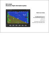
1. Position the aircraft approximately 10-15 minutes (at present groundspeed) from a VOR station.
2. Orient the aircraft to intercept a VOR course at approximately 45 degrees as shown below.
3. Adjust CDI GAIN to achieve good VOR intercept performance.
• If aircraft overshoots course during intercept, decrease CDI GAIN.
• If aircraft undershoots course during intercept, increase CDI GAIN.
• If aircraft wanders off course after intercept, increase CDI GAIN.
4. Adjust CDI DOT GAIN to achieve good VOR tracking performance.
• If aircraft oscillates while tracking course, increase CDI DOT GAIN.
• If aircraft is too slow to adjust for tracking errors, reduce CDI DOT GAIN.
10-15 minutes
Note: Avoid
Crosswinds

DOCUMENT TITLE
DOCUMENT #
REV
DATE
PAGE
Autopilot In-Flight Tuning Guide
102064-000
Revision E
1/17/2023
9
For Skyview Software Version 16.4and AFS Software Version Vx16.10
3.1.4 GPS/GPSS/LNAV/LPV Navigation Mode
Autopilot performance in GPS/GPSS/LNAV/LPV navigation modes is dependent on
performance in HDG mode and navigation signal integrity. Any changes to HDG mode tuning
will affect performance in GPS/GPSS/LPV navigation mode. To allow for optimal tuning
performance, tune the autopilot for GPS/GPSS/LNAV/LPV performance in calm winds.
Crosswind correction is applied automatically during normal operation. Ensure default XTE GAIN
and XTE DOT GAIN settings are loaded prior to commencing tuning. The following steps can be
used to tune the response when tracking GPS-based signals:
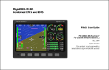
1. Position the aircraft 5 to 10 miles from runway.
2. Orient the aircraft to intercept approach course at approximately 45 degrees as shown below.
3. Adjust XTE GAIN to achieve good intercept performance.
• If aircraft overshoots course during intercept, decrease XTE GAIN.
• If aircraft undershoots course during intercept, increase XTE GAIN.
• If aircraft wanders off course after intercept, increase XTE GAIN.
4. Adjust XTE DOT GAIN to achieve good tracking performance.
• If aircraft oscillates while tracking course, increase XTE DOT GAIN.
• If aircraft is too slow to adjust for tracking errors, reduce XTE DOT GAIN.
5-10 nm
Note: Avoid
Crosswinds

PAGE
DATE
REV
DOCUMENT #
DOCUMENT NAME
10
1/17/2023
Revision E
102064-000
Autopilot In-Flight Tuning Guide
For Skyview Software Version 16.4and AFS Software Version
Vx16.10
3.1.5 Roll Tuning Troubleshooting
If performance is not acceptable, evaluate and perform the corresponding actions in the following
table. If these actions do no resolve issues, contact Dynon Technical Support.
Issue
Action(s)
ROLL SLIP indications appear.
Increase ROLL TORQUE.
Reduce ROLL SENSITIVITY
Ensure flight controls are lubricated appropriately.
Ensure flight controls are rigged appropriately.
Contact Dynon Technical Support.
Aircraft slowly wanders in heading.
Check for loose servo mount bracketry.
Check for loose flight control cables/pushrods.
Check for poor magnetometer calibration.
Ensure magnetometer is properly leveled.
Ensure magnetometer is free from magnetic interference.
Perform Servo to Flight Control Coupling Check (see Section 2.3).
Increase ROLL SENSITIVITY.
Adjust LOST MOTION COMPENSATION (see Section 6).
Contact Dynon Technical Support.
Aircraft slowly oscillates in roll
See “Aircraft slowly wanders in heading”.
Autopilot jerks or is too aggressive
Reduce ROLL SENSITIVITY.
Reduce ROLL GAIN.
Reduce LOST MOTION COMPENSATION.
Autopilot does not move controls
Ensure shear screw is not broken (see Section 2.7).
ROLL SENSITIVITY maxed out
Increase capstan radius or move pushrod toward end of servo arm.
Contact Dynon Technical Support
Table 1: Roll Axis Troubleshooting

DOCUMENT TITLE
DOCUMENT #
REV
DATE
PAGE
Autopilot In-Flight Tuning Guide
102064-000
Revision E
1/17/2023
11
For Skyview Software Version 16.4and AFS Software Version Vx16.10
3.2 Roll Axis Parameters
Parameter
Description
Default
Min
Max
ROLL TORQUE
Maximum output torque of servo.
100
10
100
ROLL HIGH
SPEED
SENSITIVITY
Amount of servo motor travel relative to autopilot output signal for roll
axis. Applied at maximum autopilot speed limit (as set in pitch servo
settings). Linear interpolation between this setting and LOW SPEED
SENSITIVITY based on airspeed. Larger numbers result in larger servo
movements for a given autopilot signal.
10
1
50
ROLL LOW
SPEED
SENSITIVITY
Amount of servo motor travel relative to autopilot output signal for roll
axis. Applied at minimum autopilot speed limit (as set in pitch servo
settings). Linear interpolation between this setting and HIGH SPEED
SENSITIVITY based on airspeed. Larger numbers result in larger servo
movements for a given autopilot signal.
10
1
50
ROLL LOST
MOTION
COMPENSATION
Amount of servo travel to compensate for mechanical control system
lost motion (aka backlash) between the servo and the control surface.
0
0
20
ROLL GAIN
Sets the overall roll error gain and feedforward signal gain. Large
numbers result in more aggressive performance and increase autopilot
response to roll errors.
0.0
0.0
5.0
CDI GAIN
Sets the autopilot response to course errors when navigating using
VOR or LOC signals.
2.0
0.1
5.0
CDI DOT GAIN
Dampens the autopilot response to course errors when navigating using
VOR or LOC signals
2.0
0.1
10.0
XTE GAIN
Sets the autopilot response to course errors when navigating using
GPS signals. Higher values increase ground track correction per unit of
course error.
0.00025
0.00000
0.01000
XTE DOT GAIN
Dampens the autopilot response to changes in course errors when
navigating using GPS signals. Higher values add dampening.
0.0005
0.0000
1.0000
BANK ANGLE
LIMIT
Bounds the desired autopilot bank angle.
30
5
45
*TURN RATE
LIMIT
Limits the rate of turn the autopilot can command.
Table 2: Roll Axis Parameters
*Only available in Advanced Flight Systems products

PAGE
DATE
REV
DOCUMENT #
DOCUMENT NAME
12
1/17/2023
Revision E
102064-000
Autopilot In-Flight Tuning Guide
For Skyview Software Version 16.4and AFS Software Version
Vx16.10
4 Pitch Axis Tuning
The pitch axis should be tuned after tuning the roll axis. Ensure all pre-flight items from
Section 2 have been completed. Failure to complete pre-flight checks is likely to prevent
successful servo tuning.
4.1 Tuning Procedures
The following procedures should be conducted in smooth air. Ensure that the high and low
autopilot airspeed limits are set appropriately before beginning these procedures.
4.1.1 Airspeed Hold Mode
With the aircraft in trimmed, level flight:
1. Set all tuning parameters to default settings.
2. Engage autopilot in HDG + IAS mode.
3. Operate the aircraft at 15 knots above minimum autopilot operating speed.
4. Raise/lower IAS bug by 10 knots and adjust LOW SPEED PITCH SENSITIVITY so pitch of
aircraft follows flight director bars.
• If aircraft lags behind flight director bars, increase LOW SPEED PITCH SENSITIVITY.
• If aircraft oscillates or feels twitchy in pitch axis, decrease LOW SPEED PITCH
SENSITIVITY.
5. Operate the aircraft at 15 knots below maximum autopilot operating speed.
6. Raise/lower IAS bug by 10 knots and adjust HIGH SPEED PITCH SENSITIVITY so pitch of
aircraft follows flight director bars.
• If aircraft lags behind flight director bars, increase HIGH SPEED PITCH SENSITIVITY.
• If aircraft oscillates or feels twitchy in pitch axis, decrease HIGH SPEED PITCH
SENSITIVITY.
7. Operate the aircraft at normal cruising speed.
8. Raise/lower IAS bug by 10 knots and adjust PITCH GAIN so aircraft smoothly captures new
airspeed setpoint.
• If aircraft overshoots new airspeed setting, reduce PITCH GAIN.
• If aircraft undershoots new airspeed setting, increase PITCH GAIN.
9. If acceptable performance is not achieved, see troubleshooting steps in Section 4.1.7.
4.1.2 Vertical Speed Mode
Performance in vertical speed mode is governed primarily by the quality of the airspeed hold
mode tuning and performance. There are no specific tuning procedures for vertical speed mode
performance.

DOCUMENT TITLE
DOCUMENT #
REV
DATE
PAGE
Autopilot In-Flight Tuning Guide
102064-000
Revision E
1/17/2023
13
For Skyview Software Version 16.4and AFS Software Version Vx16.10
4.1.3 Altitude Hold Mode
With the aircraft in trimmed, level flight:
1. Operate the aircraft at normal cruising speed.
2. Engage autopilot in HDG + ALT mode.
3. Increase altitude bug by 500 ft
4. Press NOSE UP to start VS climb at 500 fpm. Autopilot should automatically capture new
altitude. Adjust ALT GAIN to control altitude intercept performance.
• If aircraft levels-off too soon, increase ALT GAIN.
• If aircraft overshoots new altitude, decrease ALT GAIN.
5. Once new altitude has been reached adjust VSI GAIN to fine tune altitude hold performance.
• If aircraft oscillates about target altitude, increase VSI GAIN.
• If aircraft is slow to make minor corrections for altitude errors, decrease VSI GAIN.
6. Conduct a 90 degree turn by moving the heading bug.
7. Adjust G ERROR GAIN during the turn to fine tune altitude hold performance.
• If aircraft loses altitude during turn, increase G ERROR GAIN
• If aircraft still loses altitude, increase G ERROR LIMIT
8. If acceptable performance is not achieved, see troubleshooting steps in Section 4.1.7.
4.1.4 VNAV (Glideslope/ILS) Mode
Performance in all vertical navigation modes is governed primarily by the quality of the airspeed
hold mode tuning. The following settings adjust performance for the ILS glideslope mode.
Conduct this test in smooth air.
1. Operate the aircraft at normal approach speed and configuration.
2. Capture and track an ILS localizer signal using NAV mode.
3. Arm the GS mode by pressing VNAV once a glideslope signal is displayed.
4. Adjust VDI GAIN for desired glideslope capture performance
• If the aircraft overshoots the glideslope, reduce VDI GAIN.
• If the aircraft undershoots or descends too early, increase VDI GAIN.
5. Adjust VDI DOT GAIN for desired glideslope tracking performance
• If the aircraft oscillates above/below the glideslope, increase VDI DOT GAIN.
• If the aircraft is too slow to recover from glideslope, deviations reduce VDI DOT GAIN.
6. If acceptable performance is not achieved, see troubleshooting steps in Section 4.1.7.

PAGE
DATE
REV
DOCUMENT #
DOCUMENT NAME
14
1/17/2023
Revision E
102064-000
Autopilot In-Flight Tuning Guide
For Skyview Software Version 16.4and AFS Software Version
Vx16.10
4.1.5 VNAV (Glidepath/GPS) Mode
Performance in all vertical navigation modes is governed primarily by the quality of the airspeed
hold mode tuning. LPV approaches are recommended for use when tuning the autopilot due to
their inherent vertical navigation performance and accuracy. The following settings adjust
performance for the GPS glidepath mode. Conduct this test in smooth air.
1. Operate the aircraft at normal approach speed and configuration.
2. Capture and track a LPV approach course using NAV mode.
3. Arm the VNAV mode by pressing VNAV once a glidepath signal is displayed.
4. Adjust VDI GAIN for desired glideslope capture performance
• If the aircraft overshoots the glideslope, reduce VDI GAIN.
• If the aircraft undershoots or descends too early, increase VDI GAIN.
5. Adjust VDI DOT GAIN for desired glideslope tracking performance
• If the aircraft oscillates above/below the glideslope, increase VDI DOT GAIN.
• If the aircraft is too slow to recover from glideslope deviations, reduce VDI DOT GAIN.
6. If acceptable performance is not achieved, see troubleshooting steps in section 4.1.7.
4.1.6 Turbulence Tuning Procedure
The Dynon autopilot can be adjusted to compensate for small updrafts and downdrafts. These
settings can be adjusted in light turbulence or left at default values if performance is acceptable.
1. Adjust G ERROR LIMIT for desired glideslope tracking performance in turbulence
• If more aggressive correction is desired, increase G ERROR LIMIT.
• If less aggressive correction is desired, decrease G ERROR LIMIT.

DOCUMENT TITLE
DOCUMENT #
REV
DATE
PAGE
Autopilot In-Flight Tuning Guide
102064-000
Revision E
1/17/2023
15
For Skyview Software Version 16.4and AFS Software Version Vx16.10
4.1.7 Pitch Tuning Troubleshooting
If performance is not acceptable, evaluate and perform the corresponding actions in the following
table. If these actions do no resolve issues, contact Dynon Technical Support.
Issue
Action(s)
PITCH SLIP indications appear.
Ensure aircraft is kept in trim during flight.
Increase PITCH TORQUE.
Reduce PITCH SENSITIVITY.
Aircraft slowly oscillates about airspeed
setting.
Check for loose servo mount bracketry.
Check for loose flight control cables/pushrods.
Increase PITCH SENSITIVITY.
Reduce PITCH GAIN.
Increase LOST MOTION COMPENSATION (see Section 6).
Pitch servo quickly oscillates or is jerky.
Reduce PITCH SENSITIVITY.
Reduce LOST MOTION COMPENSATION (see section 6).
Aircraft overshoots altitude bug.
Reduce ALT GAIN.
Increase VSI GAIN.
Aircraft descends during turns.
Follow instructions in Section 4.1.3.
Aircraft undershoots altitude bug.
Increase ALT GAIN.
Decrease VSI GAIN.
Pitch servo oscillates during instrument
approaches or turbulence.
Decrease G ERROR GAIN.
Decrease G ERROR LIMIT.
Aircraft oscillates about altitude bug.
Increase VSI GAIN.
Follow instructions in Section 4.1.1.
Ensure no ADAHRS vibration messages exist.
Autopilot does not move controls.
Ensure shear screw is not broken (see section 2.7).
Table 3: Pitch Axis Troubleshooting

PAGE
DATE
REV
DOCUMENT #
DOCUMENT NAME
16
1/17/2023
Revision E
102064-000
Autopilot In-Flight Tuning Guide
For Skyview Software Version 16.4and AFS Software Version
Vx16.10
4.2 Pitch Axis Parameters
Parameter
Description
Default
Min
Max
PITCH TORQUE
Maximum output torque of servo.
100
10
100
PITCH HIGH SPEED
SENSITIVITY
Amount of servo motor travel relative to autopilot output signal for pitch axis.
Applied at maximum autopilot speed limit. Linear interpolation between this
setting and LOW SPEED SENSITIVITY based on airspeed. Larger numbers
result in larger servo movements for a given autopilot signal.
10
1
50
PITCH LOW SPEED
SENSITIVITY
Amount of servo motor travel relative to autopilot output signal for pitch axis.
Applied at minimum autopilot speed limit. Linear interpolation between this
setting and HIGH SPEED SENSITIVITY based on airspeed. Larger numbers
result in larger servo movements for a given autopilot signal.
10
1
50
PITCH LOST
MOTION
COMPENSATION
Amount of servo travel to compensate for mechanical control system lost
motion, or backlash, between the servo and control surface.
0
0
20
PITCH GAIN
Sets the error gain and feedforward signal gain. Large numbers result in
more aggressive performance and increase autopilot response to pitch angle
errors.
2.0
0.1
3.0
ALTITUDE GAIN
Sets the desired vertical speed based on feet of altitude error. Larger
numbers cause bigger altitude correction efforts.
0.6
0.1
2.5
*ALTITUDE
FILTERING
Adjust the time constant for filtering of altitude that feeds the autopilot.
PULL RATE
Default g’s to pull/push to correct for pitch errors.
1.0
1.0
2.0
VSI GAIN
Dampens the desired pitch angle based on vertical speed.
1.5
0.1
2.5
G ERROR GAIN
Sets the amount of pitch effort to compensate for thermals and added g-
loading during turns.
1.0
0.0
4.0
G ERROR LIMIT
Bounds the amount of pitch effort to compensate for thermals and added g-
loading during turns.
0.25
0.10
1.00
GSI GAIN
How much to change pitch rate based on glideslope error.
1.0
0.1
5.0
GSI DOT GAIN
Dampens pitch change based on glideslope error trend.
15
1
100
VDI GAIN
How much to change pitch rate based on glidepath error.
4.0
0.1
5.0
VDI DOT GAIN
Dampens pitch change based on glidepath error trend.
60
1
100
Table 4: Pitch Axis Parameters
* Only available on Advanced Flight Systems products.

DOCUMENT TITLE
DOCUMENT #
REV
DATE
PAGE
Autopilot In-Flight Tuning Guide
102064-000
Revision E
1/17/2023
17
For Skyview Software Version 16.4and AFS Software Version Vx16.10
5 Yaw Damper Tuning
The yaw damper should be tuned after tuning the roll and pitch axis. Ensure all pre-flight items
from Section 2 have been completed. Failure to complete pre-flight checks is likely to prevent
successful servo tuning.
5.1 Tuning Procedures
The following procedures should be conducted in smooth air.
5.1.1 Manual Flight Yaw Dampening
With the aircraft in trimmed, level flight:
1. Operate the aircraft at 10 knots above minimum autopilot speed.
2. Engage the yaw damper only (pitch and roll disconnected)
3. Apply small ailerons inputs to perform a Dutch Roll maneuver at the aircraft resonate frequency.
4. Adjust LOW SPEED YAW SENSITIVITY to achieve satisfactory Dutch Roll damping.
• If more rudder input is desired, increase LOW SPEED YAW SENSITIVITY.
• If less rudder input is desired, decrease LOW SPEED YAW SENSITIVITY.
• If rudder servo slips, decrease LOW SPEED YAW SENSITIVITY.
5. Set HIGH SPEED YAW SENSITIVITY to the same value as LOW SPEED YAW SENSITIVITY.
6. Operate aircraft at approximately 10 knots below the autopilot maximum airspeed.
7. Adjust HIGH SPEED YAW SENSITIVITY to achieve satisfactory yaw damping.
• If rudder servo oscillates or is jerky, decrease HIGH SPEED YAW SENSITIVITY.
• If rudder servo slips, decrease HIGH SPEED YAW SENSITIVITY.
8. If acceptable performance is not achieved, see troubleshooting steps in section 5.1.2.

PAGE
DATE
REV
DOCUMENT #
DOCUMENT NAME
18
1/17/2023
Revision E
102064-000
Autopilot In-Flight Tuning Guide
For Skyview Software Version 16.4and AFS Software Version
Vx16.10
5.1.2 Yaw Tuning Troubleshooting
If performance is not acceptable, evaluate and perform the corresponding actions in the following
table. If these actions do no resolve issues, contact Dynon Technical Support.
Issue
Action(s)
YAW SLIP indications appear.
Ensure aircraft is kept in trim during flight.
Increase YAW TORQUE.
Reduce YAW SENSITIVITY.
Slip/skid ball slowly oscillates.
Check for loose servo mount bracketry.
Check for loose flight control cables/pushrods.
Increase YAW SENSITIVITY.
Reduce RUDDER GAIN.
Yaw servo quickly oscillates or is jerky.
Reduce YAW SENSITIVITY.
Reduce LOST MOTION COMPENSATION (see Section 6).
Reduce RUDDER GAIN.
Yaw damper does not center the
slip/skid ball.
Increase YAW SENSITIVITY.
Increase RUDDER GAIN.
Increase RUDDER RATE.
Autopilot does not move controls.
Ensure shear screw is not broken (see section 2.7).
Table 5: Yaw Damper Troubleshooting

DOCUMENT TITLE
DOCUMENT #
REV
DATE
PAGE
Autopilot In-Flight Tuning Guide
102064-000
Revision E
1/17/2023
19
For Skyview Software Version 16.4and AFS Software Version Vx16.10
5.2 Yaw Damper Parameters
Menu Parameter
Description
Default
Min
Max
YAW TORQUE
Maximum output torque of servo.
100
10
100
YAW HIGH SPEED
SENSITIVITY
Amount of servo motor travel relative to autopilot output signal for yaw
axis. Applied at maximum autopilot speed limit. Linear interpolation
between this setting and LOW SPEED SENSITIVITY based on
airspeed. Larger numbers result in larger servo movements for a given
autopilot signal.
10
1
50
YAW LOW SPEED
SENSITIVITY
Amount of servo motor travel relative to autopilot output signal for yaw
axis. Applied at minimum autopilot speed limit. Linear interpolation
between this setting and HIGH SPEED SENSITIVITY based on
airspeed. Larger numbers result in larger servo movements for a given
autopilot signal.
10
1
50
YAW LOST MOTION
COMPENSATION
Amount of servo travel to compensate for mechanical control system
lost motion, or backlash, between the servo and control surface.
0
0
20
RUDDER GAIN
Sets the error gain and feedforward signal gain. Large numbers result
in more aggressive damping performance and increase autopilot
response to yaw excursions. Changing this setting is not
recommended.
Proportional gain for AZ gyro.
0.2
0.0
2.5
RUDDER RATE
How fast to apply ball-centering rudder input. Changing this setting is
not recommended.
Integral gain for the AZ gyro.
0.005
0.001
0.500
AY GAIN
Sets the output gain to the ball-centering rudder subroutine.
0.000
0.000
2.500
*RUDDER LEAD
Sets the amount of cross-mixing between roll error and rudder output.
0.0
0.000
9.900
*RUDDER LEAD LIMIT
Bounds the amount of cross-mixing between the roll error and rudder
output.
1.0
0.0
9.9
Table 6: Yaw Damper Parameters
* Only available on Advanced Flight Systems products.
/