Page is loading ...

Copyright © 2011, Tjernlund Products, Inc. All rights reserved. P/N 8504160
REV. A 3/11
RECOGNIZE THIS SYMBOLAS AN INDICATION OF IMPORTANT SAFETY INFORMATION!
THESE INSTRUCTIONS ARE INTENDED AS AN AID TO QUALIFIED, LICENSED SERVICE PERSON-
NEL FOR PROPER INSTALLATION, ADJUSTMENT AND OPERATION OF THIS UNIT. READ THESE
INSTRUCTIONS THOROUGHLY BEFORE ATTEMPTING INSTALLATION OR OPERATION. FAILURE
TO FOLLOW THESE INSTRUCTIONS MAY RESULT IN IMPROPER INSTALLATION, ADJUSTMENT,
SERVICE OR MAINTENANCE POSSIBLY RESULTING IN FIRE, ELECTRICAL SHOCK, CARBON
MONOXIDE POISONING, EXPLOSION, PERSONAL INJURY OR PROPERTY DAMAGE. THIS INSTAL-
LATION MANUAL DOES NOT CONTAIN ANY SYSTEM DESIGN DOCUMENTATION.
!
DO NOT DESTROY. PLEASE READ CAREFULLY AND KEEP IN
A SAFE PLACE ON JOB SITE FOR FUTURE REFERENCE.
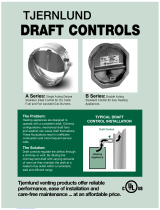
RT750 & RT1500
For Gas & Oil Applications
RT750H & RT1500H
For Solid Fuel Applications
Rooftop Inducers
FOR NATURAL GAS, LP, OIL-FIRED,
SOLID FUEL HEATING APPLIANCES
AND GENERAL VENTILATION
TJERNLUND PRODUCTS, INC.
1601 Ninth Street • White Bear Lake, MN 55110-6794
PHONE (800) 255-4208 • (651) 426-2993 • FAX (651) 426-9547
Visit our web site • www.tjernlund.com
Rooftop Inducers are tested and Listed to UL
Standard 378 for Draft Equipment
Rated up to 1000° F
Rooftop Inducers are tested and Listed to
ANSI/UL 705-2004 Power Ventilators
Rooftop Inducers are tested and Listed to CAN3-B255-M81
for Mechanical Flue-Gas Exhausters
Restricted to Non-Solid Fuel applications only under the
scope of standard CAN3-B255-M81
Rated up to 575° F / 300° C in Canada
For non-condensing applications only. Not suitable for Side Wall terminations.
IMPORTANT: Use of this product could cause flues to reverse (back-draft) on other heating equipment with-
in the same structure if adequate make-up air is not provided. Check for flue gas spillage of atmospheri-
cally vented heaters after rooftop Inducer installation and always have working carbon monoxide detectors
installed per the CO detector manufacturer’s instructions and local codes. Make-up / combustion air fans
are available from Tjernlund if necessary.

TABLE OF CONTENTS
PAGE(S)
DESCRIPTION ............................................................................................................................................................. 1
DIMENSIONS AND SPECIFICATIONS ........................................................................................................................ 1
FAN PERFORMANCE CURVES.....................................................................................................................................2
INSTALLATION RESTRICTIONS & CAUTIONS ........................................................................................................... 3
INSTALLER RESTRICTIONS & CAUTIONS IN FRENCH CANADIAN ..................................................................... 3-4
TERMINATION CLEARANCES FOR CANADIAN & U.S. INSTALLATIONS................................................................. 4
INSTALLATION .......................................................................................................................................................... 5-7
RT750 / RT1500 - PSA-1 FAN PROVING SWITCH INSTALLATION .......................................................................... 7
WIRING OPTIONS.....................................................................................................................................................8-11
SIZING A COMMON MANIFOLD SERVING MULTIPLE HEATERS ............................................................................12
RT750 / RT1500 - PSA-1 SAFETY INTERLOCK AND DRAFT ADJUSTMENT SET-UP PROCEDURE....................13
RT750H / RT1500H SPEED CONTROL ADJUSTMENT ...................................................................................... 13-14
COMBUSTION AIR ......................................................................................................................................................14
INSPECTION & MAINTENANCE .................................................................................................................................14
TROUBLESHOOTING .................................................................................................................................................14
HOW TO OBTAIN SERVICE & LIMITED WARRANTY ..........................................................................................14-15
REPLACEMENT PARTS ..............................................................................................................................................15
Tjernlund Products welcomes your comments and questions. Call us at 800-255-4208, Fax 651-426-9547, Email us at
[email protected] or write to: Customer Service, Tjernlund Products, Inc., 1601 Ninth Street, White Bear Lake, MN 55110-6794.
DESCRIPTION
RT750 & RT1500 models are supplied with the model PSA-1 Fan Proving Switch which will disable the burner(s) if an Inducer mal-
function should occur and are compatible with Tjernlund UC1, UCRT and DCOP1 interlock controls. The RT750H & RT1500H are
supplied with a wall mount speed control to vary inducer performance in solid fuel applications. The Rooftop Inducer may be used on
positive or negative pressure rated chimneys because the fan creates a negative pressure throughout the entire venting system.
Suitable for use on natural gas, LP-gas, oil-fired, solid fuel heating systems or general ventilation. Also applicable for dryers, gas fire-
places, stoves, BBQ’s or pizza ovens. The Rooftop Inducer must always be installed outdoors at the vent system termination. Refer to
heating appliance manufacturer's instructions regarding specific venting requirements.
GENERAL SELECTION INFORMATION
Selection of a Rooftop Inducer involves determination of the maximum volume of air or gases to be handled, their density and the
maximum static pressure which the fan must overcome. Rooftop Inducer performance needs to be de-rated from 70OF performance
curves to anticipated air or gas temperatures. Please feel free to contact us for application and model selection assistance by calling
800-255-4208 or email us at [email protected]. Vent layout or other information can be faxed to 651-426-9547. See “Sizing a
Common Manifold Serving Multiple Heaters” on Page 12 for manifold considerations.
DIMENSIONS AND SPECIFICATIONS
1
.373.063kW
lbs
kgs
in
in
mm
in
mm
in
mm
in
mm
mm
E
D
Weight
Dimensions
C
B
A
11 15/167 15/16
14 1/2
368
201 17
432
303
8
16
406
203
34
15.42
16 3/4
425
18 1/2
470
286
11 1/4
21.32
552
21 3/4
47
hp
MODEL
Voltage
RPM
Amps
Power Rating
120 VAC
1.2
1/12
1550
RT750H
RT750
120 VAC
5.8
1/2
1550
RT1500H
RT1500
F
mm
in
22 1/2
572445
17 1/2
( )
inlet
D
E
F
B
C
A

ROOFTOP INDUCER SELECTION TABLES
2
00 200 400 600 800 1000
CFM (STD. AIR 70 DEGREES F)
STATIC PRESSURE (INCHES W.C.)
0
RT12 SERIES
1000800600400200
0.4
0.3
0.2
0.1 0.1
0.2
0.3
0.4
8069016
1200 1400 1600 1800
0
0.8
0.7
0.6
0.5
1800160014001200
0.5
0.6
0.7
0.8
1.0
0.9 0.9
1.0
(120 VAC)
MINIMUM SPEED
WITH TJERNLUND
SPEED CONTROL
MODELS RT1500 & RT1500H
OPERATING
RANGE
MAXIMUM SPEED
WITH TJERNLUND
SPEED CONTROL
1.1 1.1
RT8 SERIES
MODELS RT750 & RT750H
OPERATING
RANGE
(120 VAC)
MAXIMUM SPEED
MINIMUM SPEED
WITH TJERNLUND
SPEED CONTROL
WITH TJERNLUND
SPEED CONTROL
00 100 200 300 400 500
CFM (STD. AIR 70 DEGREES F)
STATIC PRESSURE (INCHES W.C.)
0
500400300200100
0.4
0.3
0.2
0.1 0.1
0.2
0.3
0.4
8069015
600 700 800 900
0
0.8
0.7
0.6
0.5
900800700600
0.5
0.6
0.7
0.8
1.0
0.9 0.9
1.0
MODELS RT750 & RT750H MODELS RT1500 & RT1500H
*IMPORTANT: Select the inducer based on the BTU/hr input of the appliance(s) rather than
the diameter of the appliance(s) vent outlet or chimney. Vent/Chimney sizes listed are the
smallest inside diameter recommended for the associated BTU/hr input. Use a tapered reduc-
ing collar or transition fitting if the vent is reduced to the pipe diameter listed in selection table.
To determine equivalent feet, add the total length of straight vent pipe plus 10 feet for each 90
degree elbow and 5 feet for each 45 degree elbow.
ROOFTOP INDUCER FAN CURVES
Models RT750 & RT1500 Selection
Table for Gas & Oil Applications Models RT750H & RT1500H
Selection for Solid Fuel Fireplaces
Efficient draft that moves smoke up the chimney and
keeps it from entering the living area is dependent on
maintaining a negative pressure capture velocity at the
hearth opening. Even if glass fireplace doors are present,
reducing the open area, a negative pressure capture
velocity must be calculated based on the entire hearth
opening since the doors need to be opened to add addi-
tional logs.
Multiply the vertical and horizontal hearth opening to
determine the face area opening in square feet. If the
fireplace is open on the sides or back total all openings
to arrive at the total face area.
If typically the fire can be maintained but smoke drifts into
the room, select the model which has a face area capaci-
ty equal or greater than the face opening.
Maximum Face Area:
RT750H 14 Ft²
RT1500H 28 Ft²
Tjernlund offers free design recommendations for unusu-
al fireplace designs, such as free-standing and custom
gas fireplaces. If in doubt, consult factory.

3
INSTALLATION RESTRICTIONS
Failure to install, maintain and/or operate the Rooftop Inducer in accordance with manufacturer's instructions may result in conditions
which can produce bodily injury and property damage.
The Rooftop Inducer must be installed by a qualified installer in accordance with these instructions and all local codes or in their
absence in accordance with the latest edition of The National Fuel Gas Code (NFPA 54), NFPA 211 or 31 when applicable, the latest
edition of the National Electrical Code (NFPA 70) and the Occupational Safety and Health Act (OSHA) when applicable. In the
absence of local codes in Canada, installations must comply with the Canadian Electrical Code (CSA Std 22.1 ), the latest edition of
the Natural Gas Installation Code (CAN/CGA-B149.1), the Propane Installation Code (CAN/CGA-B149.2) and the Installation Code for
Oil Burning Equipment (CSA Std B139-M91).
Improper installation can create a hazardous condition such as an explosion, fire, electrical shock or carbon monoxide poisoning
resulting in property damage, personal injury or death.
1. The Rooftop Inducer may be installed on natural gas, LP-gas, oil-fired, solid fuel heating systems or general ventilation systems.
The Rooftop Inducer is not suitable for use on condensing equipment.
2. The Rooftop Inducer was tested with exit flue gas temperatures of 1000OF (537OC) U.S. and 575OF (300OC) Canada.
3. The Rooftop Inducer may not be installed on incinerators or incinerating toilets.
4. The Rooftop Inducer must always be installed at the vent system termination. Not suitable for Side Wall terminations.
5. The Rooftop Inducer shall not be installed on an appliance with an automatic valve having a manual opener unless the manual
opener has been rendered inoperative or the automatic valve has been replaced with a valve not equipped with a manual opener.
6. RT750 / RT1500 Rooftop Inducers may only be installed on appliances equipped with a draft hood, draft diverter, barometric
draft control or other dilution air providing source.
The Rooftop Inducer is designed to fit any type of nominal (8" Models RT750 / RT750H) or (12" Models RT1500 / RT1500H) diame-
ter vent pipe. Vent pipe must be installed and supported according to manufacturer's instructions and/or in accordance with NFPA211,
"Chimneys and Vents". Factory insulated vent pipe may reduce clearances to combustibles when penetrating a combustible roof.
Refer to vent pipe manufacturer's instructions for details.
INSTALLER CAUTIONS
Disconnect the power supply when making wiring connections or when working around the Inducer impeller and motor. Failure to do
so can result in electrical shock, personal injury, death or property damage.
1. The model PSA-1 Fan Proving Switch provided must be interlocked with the heating appliance burner(s).
2. Plan the vent system so that the code required clearances are maintained from plumbing, wiring and combustibles.
3. Make certain the power supply is adequate for Rooftop Inducer motor requirements. Do not add the Rooftop Inducer to a circuit
where the total load is unknown.
4. The installer must verify that the appliance(s) on which the Rooftop Inducer will be installed is in a safe operating condition. Consult
appliance manufacturer's Instructions for details.
5. Rooftop Inducer housing is single wall. Standard clearances to combustibles must be maintained.
CONDITIONS D'INSTALLATION
Ne pas installer, entretenir et(ou) utiliser le Système d'admission d'air pour toit conformément aux directives du fabricant pourrait
entraîner des circonstances qui causeront des blessures et endommageront la propriété.
Le Système d'admission d'air pour toit doit être installé par un installateur qualifié conformément aux présentes directives et à toutes
les normes applicables à la localité. En l'absence de normes locales au Canada, les installations doivent respecter le Code canadien
de l'électricité (CSA Std 22.1), la dernière version du Code d'installation du gaz naturel (CAN/CGA-B149.1), le Code d'installation du
propane (CAN/CGA-B149.2) et le Code d'installation des appareils de combustion au mazout (CSA Std B139-M91).
Une installation inadéquate pourrait entraîner un danger, comme une explosion, un feu, une décharge électrique ou un empoison-
nement au monoxyde de carbone qui endommagera la propriété, occasionnera des blessures ou même la mort.
1. Le Système d'admission d'air pour toit peut être installé sur des systèmes de chauffage aux gaz naturels, aux gaz de pétroles
liquéfiés, au mazout ou aux combustibles solides ou systèmes de ventilation générale. Le Système d'admission d'air pour toit ne
convient pas aux systèmes de condensation.

4
2. Le Système d'admission d'air pour toit a été testé à des températures des gaz à la sortie du conduit de 575°F (300°C) Canada.
3. Le Système d'admission d'air pour toit ne doit pas être installé sur des incinérateurs, des cuvettes sanitaires à incinération ou des
appareils brûlant un combustible solide.
4. Le Système d'admission d'air pour toit doit toujours être installé à l'extrémité du système de ventilation. Il ne doit être monté
qu'en plaçant l'arbre de moteur à la verticale.
5. Le Système d'admission d'air pour toit ne doit pas être installé sur un appareil équipé d'une valve automatique ayant un dispositif
d'ouverture manuel, à moins que le dispositif d'ouverture manuel ne fonctionne plus ou que la valve automatique a été remplacée
par une valve sans dispositif d'ouverture manuel.
6. Les modèles RT750 / RT1500 du Système d'admission d'air pour toit ne peuvent être installés que sur les appareils équipés
d'un coupe-tirage, d'une hotte de tirage, du réglage barométrique du tirage ou toute autre source de ventilation de dilution.
Le Système d'admission d'air pour toit est conçu pour tout tuyau de ventilation d'un diamètre nominal de (8" Modèles RT750 /
RT750H) ou (12" Modèles RT1500 / RT1500H). Un tuyau de ventilation isolé en usine pourrait réduire les distances sécuritaires req-
uises par rapport aux matières inflammables lorsqu'il pénètre un toit ou un mur inflammable. Pour de plus amples renseignements,
consultez les directives du fabricant du tuyau de ventilation.
PRÉCAUTIONS À PRENDRE PAR L'INSTALLATEUR
Débranchez le bloc d'alimentation avant d'effectuer des branchements électriques ou de travailler autour du rotor et du moteur du
ventilateur, afin de ne pas être victime d'une décharge électrique, de blessures et même de mort, ou d'endommager la propriété.
1. L'interrupteur de vérification du ventilateur du modèle PSA-1 fourni doit être interverrouillé avec le ou les brûleurs de l'appareil de
chauffage.
2. Montez le système de ventilation en respectant les normes de distances sécuritaires du code par rapport à la plomberie, au filage
électrique et aux matières inflammables.
3. Assurez-vous que le bloc d'alimentation convient aux exigences du moteur du Système d'admission d'air pour toit. N'ajoutez pas le
Système d'admission d'air pour toit à un circuit dont vous ignorez la charge totale.
4. Le technicien doit vérifier que l'appareil sur lequel sera installé le Système d'admission d'air pour toit est dans une condition d'utili-
sation sécuritaire. Pour de plus amples renseignements, consultez les directives du fabricant de l'appareil.
5. Le Système d'admission d'air pour toit est logé dans un seul mur. Il faut respecter les normes de distances sécuritaires par rapport
aux matières inflammables.
ROOFTOP INDUCER TERMINATION CLEARANCES
U.S. INSTALLATIONS
Terminate the Rooftop Inducer so that proper minimum clearances are maintained as cited in the latest edition of the National Fuel
Gas Code (NFPA 54), NFPA 211 or 31 when applicable.
CANADIAN INSTALLATIONS
In the absence of local codes in Canada, installations must comply with the latest edition of the Natural Gas Installation Code
(CAN/CGA-B149.1), the Propane Installation Code (CAN/CGA-B149.2), the Installation Code for Oil Burning Equipment (CSA Std
B139-M91) or as follows:
The Rooftop Inducer base must be a minimum of 9” above a roof. Optional roof mounting kits are available from Tjernlund.
• A venting system shall not direct flue gases so as to jeopardize people, overheat combustible structures, or enter buildings.
Aventing system shall not terminate within (4 ft U.S.) (1.8 m / 6ft Canada) of the following:
• A window, door or mechanical air supply inlet of any building
• A gas service regulator vent outlet
• A combustion air inlet
• A direction facing combustible materials or openings of surrounding buildings
Aventing system shall not terminate within 1m (3ft) of the following:
• At least 3 feet above any forced air inlet located within 10 feet.
• Above a gas meter/regulator assembly within 1m (3ft) horizontally of the vertical centreline of the regulator
• An oil tank or an oil tankfill inlet

5
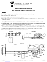
INSTALLATION OF ROOFTOP INDUCER
The Rooftop motor side is heavy. Remove (2) hinge pins and (2) latch screws opposite hinge side to separate the motor sec-
tion from the mounting base prior to installation. When removing the motor side, use extreme caution so internal parts such
as the impeller are not damaged.
Make sure vent pipe is adequately installed and supported for weight of inducer. Tjernlund’s optional RT-Series rooftop stands or a
frame to support weight of inducer may be necessary. The vent extending above the roofline may be shortened for a more stable and
aesthetic installation since the Rooftop Inducer provides draft regardless of chimney height.
IMPORTANT: Disconnect the power supply when making wiring connections or when working around the fan impeller and motor.
Failure to do so can result in electrical shock, personal injury, death or property damage.
INDUCER BASE INSTALLATION
All models include mounting kits to securely attach the Inducer Base to any type of insulated
or single wall metal pipe or tile lined flue.
MOUNTING INDUCER BASE ON METAL VENT PIPE
NOTE: Discard adapter plate, finger clamps and 3 1/2” bolts if mounting on metal vent pipe.
A Mounting Plate and Inlet Collar is included with each Rooftop Inducer. The RT750 Series
collar will slip inside any metal pipe as small as 8" diameter ID and as large as 12” OD. The
RT1500 Series collar will slip inside any metal pipe as small as 12" ID and as large as 20” OD.
If your application has a metal pipe smaller than the noted diameters use an increaser appro-
priate for pipe type to transition to minimum diameter noted.
1. Insert Inlet Collar through Mounting Plate. Place Inducer Base on top of Inlet Collar and
Mounting Plate to sandwich Inlet Collar flange between them. Insert (4) 1/2” 10-32 carriage
bolts through Mounting Plate and Inducer Base and tighten (4) 10-32 lock nuts on top of
Inducer Base. Secure (4) Pipe Straps to the holes on the sides of the Inducer Base with
included (4) 3/8” 8-32 screws and lock nuts, (See Diagram A).
2. IMPORTANT: Before inserting Inlet Collar / Inducer Base assembly into vent pipe note that
the electrical connection is on the hinged side of the Inducer. Make sure that the Inducer
Base is positioned so that Inducer swings towards the desired direction. Using RTV or
equivalent high temperature silicone apply a generous bead to the top edge of the metal
vent pipe. Insert Inlet Collar / Inducer Base assembly into vent pipe considering hinge loca-
tion. Insert the large adjustable pipe clamp through the loops of the pipe straps and tighten
pipe clamp until it snugly grips the OD of the vent. NOTE: RT1500 Series will have to use
both pipe clamps provided, (See Diagram B).
DIAGRAM A
DIAGRAM B
INSTALLATION ISOMETRIC FOR
TILE LINED CHIMNEY
INSTALLATION ISOMETRIC FOR
METAL VENT PIPE
INDUCER BASE
INLET COLLAR
MOUNTING PLATE
PIPE STRAPS (4)
PLACE A GENEROUS BEAD OF HIGH TEMP SILICONE
ON TOP OF PIPE BEFORE PLACING INLET COLLAR /
INDUCER BASE ASSEMBLY ON VENT PIPE. INSERT
PIPE CLAMP THROUGH STRAPS AND TIGHTEN.

6
MOUNTING INDUCER BASE ON CLAY TILE FLUE LINERS
NOTE: Discard mounting plate, pipe straps and pipe clamps if mounting on a tile flue liner.
1. Flip the Inducer Base bottom side up and position finger clamps in each corner. Place washer on (4) 3 1/2" adjustment bolts and
insert through holes in corners and thread into finger clamp. Insert (4) 1/2” 10-32 carriage bolts through slots in finger clamps
and through Inducer Base holes. Loosely secure on top side of Inducer Base with included (4) 10-32 lock nuts, (See Diagram C).
2. Place a generous bead of RTV or equivalent high temperature silicone on top of tile liner, (See Diagram D). Position the
Inducer Base on top of the chimney liner, inserting the finger clamps into the liner interior. IMPORTANT: Note location of hinges to
make sure that the Inducer Base is positioned so that Inducer swings towards the desired direction. The electrical whip is located
on the hinged side. Once positioned in center of flue, pull the head of each 3 1/2” adjustment bolts out until the finger clamps make
contact with the interior wall of the liner. Tighten opposite corners until finger clamps firmly secure the Inducer Base to the liner inte-
rior. CAUTION: Over-tightening could crack tile liner, (See Diagram E).
3. When finger clamps are firmly tightened, tighten down finger clamp 10-32 lock nuts on top of Inducer Base, (See Diagram F).
4. Place Adapter Plate on Inducer Base and mark Adapter Plate underside with a marker by tracing the interior of chimney,
CAUTION: Sharp edges-wear gloves. If underside cannot be easily marked take measurements of chimney to determine Adapter
Plate opening, (See Diagram G).
5. If Adapter Plate can’t be easily marked by tracing interior of chimney, mark center lines on Adapter Plate and use chimney opening
measurements to mark the Adapter Plate to cut out chimney opening, (See Diagram H).
6. Fill any gaps on exterior of chimney flue and
Inducer Base with RTV or equivalent high
temperature silicone, (See Diagram I).
7. Use a tin snips or equivalent to cut marks made
on Adapter Plate to expose inside of tile liner.
Confirm Adapter Plate opening exposes full
chimney opening. Place a thin bead of RTV or
equivalent high temperature silicone around
Adapter Plate opening and place silicone side
down on Inducer Base, (See Diagram J).
DIAGRAM C DIAGRAM D DIAGRAM E
DIAGRAM F DIAGRAM G DIAGRAM H
EITHER MARK ADAPTER PLATE FROM UNDER-
SIDE (CAUTION: METAL IS SHARP WEAR
GLOVES) OR TAKE MEASUREMENTS OF CHIM-
NEY TO DETERMINE ADAPTER PLATE OPENING.
IF ADAPTER PLATE CAN’T BE EASILY MARKED
BY TRACING INSIDE OF CHIMNEY, MARK CEN-
TER LINES ON ADAPTER PLATE AND USE
MEASUREMENTS FROM STEP 4 TO MARK
LINES FOR ADAPTER PLATE OPENING.
DIAGRAM J
USE A TIN SNIPS OR EQUIVALENT TO CUT
MARKS MADE ON ADAPTER PLATE TO
EXPOSE INSIDE OF TILE LINER. CONFIRM
ADAPTER PLATE FULLY EXPOSES INSIDE OF
CHIMNEY AND ADHERE TO INDUCER BASE
WITH A THIN BEAD OF HIGH TEMP SILICONE.
DIAGRAM I
FILL ANY OPEN AREA BETWEEN EXTERIOR OF
CHIMNEY FLUE AND INDUCER BASE PLATE
WITH RTV OR EQUIVALENT HIGH TEMPERA-
TURE SILICONE.
WHEN FINGER CLAMPS ARE FIRMLY TIGHTENED,
TIGHTEN DOWN FINGER CLAMP LOCK NUTS ON
TOP OF INDUCER BASE.
INSERT 3 1/2" ADJUSTMENT BOLTS & WASHER
THRU HOLES IN CORNERS, THREAD INTO FINGER
CLAMP. INSERT STAINLESS 10-32 CARRIAGE BOLTS
THROUGH SLOTS IN FINGER CLAMPS INDUCER
BASE HOLES. LOOSELY SECURE ON TOP SIDE OF
INDUCER BASE WITH INCLUDED 10-32 LOCK NUTS.
PLACE A GENEROUS BEAD OF RTV OR
EQUIVALENT HIGH TEMPERATURE SILICONE
ON TOP OF CHIMNEY TILE LINER.
TIGHTEN OPPOSITE CORNERS UNTIL FINGER
CLAMPS SNUGLY SECURE THE INDUCER BASE
TO THE LINER INTERIOR. CAUTION: OVER-
TIGHTENING COULD CRACK TILE LINER.

7
ROOFTOP INDUCER MOUNTING AND SCISSOR HINGE ASSEMBLY
Set the Inducer top motor side on top of the Inducer Base, aligning the hinges. Insert the two hinge pins with the heads on the outside portion
of the hinges, (See Diagram K).
Install hinges as follows: Inducer Top hinge: Insert 1/2” threaded stud through Inducer top, (2) washers, hinge (with stop on outside), spacer,
washer and 10-32 lock nut. Inducer Base hinge: Insert 1/2” threaded stud through Inducer Base, washer, hinge (with stop outside), spacer,
(2) washers and 10-32 lock nut, (See Diagram L). Use (2) provided 3/8” 8-32 self tapping screws to secure Inducer top to Inducer Base
through the two oval brackets on front of Inducer.
Insert Discharge Grilles inside Inducer Base on both sides with (3) 3/8” 8-32 self tapping screws provided. IMPORTANT: Grilles must be
installed on inside of Inducer Base, (See Diagram M).
MODEL RT750 / RT1500 - PSA-1 FAN PROVING SWITCH INSTALLATION
The RT750 and RT1500 models include the adjustable fan prov-
ing switch model PSA-1. Follow these general procedures for
pressure switch installation and adjustment. NOTE: If using the
DCOP1 control follow “Vent Pipe Sensing Sampling Tube & PSA-1
Fan Prover Location & Installation” section in DCOP1 manual.
1. Install Fan Proving Switch sampling tube in the vent con-
nector 2-3 pipe diameters after the elbow or "T" that turns
the vent from heater flue outlet from vertical to horizontal.
For multiple heater venting into a common manifold, install
after heater closest Rooftop Inducer. If the vent run is
completely vertical, install after draft hood or barometric
draft control. Installing the sampling tube nearer the Inducer
will make the adjustment easier because the pressure
sensed will be more negative and eliminate sensing pres-
sure near the switch’s bottom-end range, (See Diagram N)
2. Using a sharp drill bit to reduce burr, drill a 1/4" hole for
Fan Proving Switch sampling tube. Screw sampling tube
bracket to pipe with sampling hole centered, (See Diag. O).
3. Insert stainless steel sampling tube through 1/4" hole
enough to just penetrate interior of vent pipe and lock in
place with compression nut, (See Diagram O). With the
Rooftop Inducer on, a reading with a draft gauge can be
used to determine when interior of pipe has been penetrated.
4. IMPORTANT: Fan Proving Switch diaphragm must be mounted in a vertical position within six feet of the sensing location. Firmly
insert flexible tubing on sampling tube and Fan Proving Switch nipple marked (LOW). Leave other Fan Proving Switch port open
to room atmosphere. Make sure there are no sharp bends or kinks in flexible tubing, (See Diagram P).
DIAGRAM K DIAGRAM L DIAGRAM M
INSERT BOTH HINGE PINS. ASSEMBLE HINGES ON BOTH SIDES PER
DIAGRAM. NOTE: STOPS MUST FACE OUT. INSERT BOTH DISCHARGE GRILLES ON INSIDE OF
INDUCER BASE WITH (3) SELF TAPPING SCREWS.
STOP FACING OUT
1/2” THREADED
STUDS
INDUCER TOP
INDUCER BASE
FIGURE 8052070
TJERNLUND ROOFTOP
DRAFT INDUCER
(MUST BE MOUNTED
SIX FEET OF SENSING
VERTICALLY WITHIN
FAN PROVING SWITCH
LOCATION)
APPLIANCE
GAS APPLIANCE DRAFT
SAMPLE LOCATION
FLAME RETENTION
OIL BURNERS
OVER-FIRE DRAFT
DRAFT CONTROL
/ DRAFT HOOD
TJERNLUND ABD-SERIES
BALANCING BAFFLE
(IF BAFFLE IS INSTALLED
IT MUST BE POSITIONED
AFTER FAN PROVING SWITCH)
DIAGRAM N
DIAGRAM P
FAN PROVING SWITCH MUST
BE MOUNTED WITHIN SIX
FEET OF SAMPLING TUBE.
IMPORTANT:
SWITCH CAN BE ORIENTATED
IN A 360OPLANE AS LONG AS
DIAPHRAGM IS IN A VERTICAL
ORIENTATION AND TUBING IS
NOT KINKED.
DIAGRAM O
1/4” STAINLESS STEEL
SAMPLING TUBE BEND MUST
FACE UPWARD
COMPRESSION FERRULE
COMPRESSION NUT
SAMPLING PORT CENTERED
OVER 1/4” HOLE

8
WIRING
INSTALLING ELECTRICAL WHIP
Remove the (2) 8-32 nuts holding coverplate and gasket on the electrical access of the Inducer.
Pull the wires out of the Inducer and wire nut them to the electrical leads from the whip referenc-
ing appropriate diagram below. Carefully stuff the wired connections back into the Inducer and
secure coverplate and gasket to Inducer housing using the nuts removed from above. Firmly
tighten until gasket compresses, (See Diagram Q).
Secure box on opposite end of whip to power supply conduit and wire in accordance to the
diagram appropriate for installation. Place provided gasket between cover and box firmly tighten.
All wiring from the Rooftop Inducer to the appliance must be in compliance with local codes or in their absence, the National Electric
Code (NFPA 70).
All wiring from the Rooftop Inducer to the appliance must be appropriate class 1 wiring as follows: Installed in rigid metal conduit,
intermediate metal conduit, rigid non-metallic conduit, electrical metallic tubing, Type MI Cable or be otherwise suitably protected from
physical damage.
MOTOR
CAPACITOR
GND
L1
MTR
N
WHITE
BLACK
RED
ORANGE
BROWN
MTR
NEUT
WHT / RED
COOLING FAN
THERMOSTAT
INDUCER
MOTOR
THERMOSTAT
WHT / RED
BLACK
BROWN
ORANGE
BROWN
RED
NUTS
ORANGE
BLACK
RED
WHT / RED
WHITE WHITE
BLUEBLUEBLACK
PRE-WIRED 4 FT. WHIP
INCLUDED
INCLUDED 4 X 4 BOX
CUTAWAY SIDE VIEW
IMPELLER
WIRE
BLACK
VAC
115
FIGURE 8052071 3-3-11
ROOFTOP INDUCER ELECTRICAL WHIP CONNECTIONS
DIAGRAM Q

9
MOTOR
CAPACITOR
GROUND
BLACK
WHITE
RED
BROWN
WHITE / RED
COOLING FAN
THERMOSTAT
INDUCER
MOTOR
THERMOSTAT
WHT / RED
BLACK
BROWN
ORANGE
BROWN
RED
NUTS
ORANGE
BLACK
RED
WHT / RED
WHITE WHITE
BLUEBLUEBLACK
4 FT. WHIP
PRE-WIRED
INCLUDED 4 X 4 BOX
IMPELLER
WIRE
BLACK
INCLUDED
ORANGE
SIDE VIEW
CUTAWAY
RT SERIES
WHITE
BLACK
RED
CONTROL OPTION 1
MANUAL ON / OFF
(BLACK)
(WHITE)
(GREEN / BARE COPPER)
L1
N
SWITCH IS PROVIDED BY OTHERS, MUST BE
RATED FOR 10 AMPS MINIMUM AT 120 VAC.
NOTE:
115 VAC RED
BLACK
FIGURE 8052072 3-7-11
FIGURE 8052073 3-7-11
MOTOR
CAPACITOR
GROUND
BLACK
WHITE
RED
BROWN
WHITE / RED
COOLING FAN
THERMOSTAT
INDUCER
MOTOR
THERMOSTAT
WHT / RED
BLACK
BROWN
ORANGE
BROWN
RED
NUTS
ORANGE
BLACK
RED
WHT / RED
WHITE WHITE
BLUEBLUEBLACK
4 FT. WHIP
PRE-WIRED
INCLUDED 4 X 4 BOX
IMPELLER
WIRE
BLACK
INCLUDED
ORANGE
SIDE VIEW
CUTAWAY
RT SERIES
WHITE
BLACK
RED
CONTROL OPTION 2
MANUAL SPEED CONTROL
(BLACK)
(WHITE)
(GREEN / BARE COPPER)
L1
N
USE TJERNLUND ROOFTOP SERIES SPEED
CONTROLS ONLY. WARRANTY IS VOIDED IF
NOTE:
115 VAC OFF
ON
LOW
ON
HIGH
SPEED
CONTROL
RED
BLACK
A DIFFERENT SPEED CONTROL IS USED.
MANUAL ON/OFF OPERATION
MANUAL SPEED CONTROL (INCLUDED WITH RT750H / RT1500H)

10
MOTOR
CAPACITOR
GROUND
BLACK
WHITE
RED
BROWN
WHITE / RED
COOLING FAN
THERMOSTAT
INDUCER
MOTOR
THERMOSTAT
WHT / RED
BLACK
BROWN
ORANGE
BROWN
RED
NUTS
ORANGE
BLACK
RED
WHT / RED
WHITE WHITE
BLUEBLUEBLACK
4 FT. WHIP
PRE-WIRED
INCLUDED 4 X 4 BOX
IMPELLER
WIRE
BLACK
INCLUDED
ORANGE
SIDE VIEW
CUTAWAY
RT SERIES
WHITE
BLACK
RED
(BLACK)
(WHITE)
(GREEN / BARE COPPER)
L1
N
115 VAC
RED
BLACK
GND
CONTROL OPTION 3
HEATING APPLIANCE INTERLOCK USING UC1
N
L
N
M
MTR
P2
P1
CONTROL
TJERNLUND UC1
INTERLOCK OPTIONS
INSTRUCTIONS FOR
SEE UC1
PSA-1
TJERNLUND
5 VDC BOARD-GENERATED POWER.
115 VAC
LEGEND
DO NOT SUPPLY POWER!
WHITE
FIGURE 8052074 3-7-11
FIGURE 8052075 3-7-11
MOTOR
CAPACITOR
GROUND
BLACK
WHITE
RED
BROWN
WHITE / RED
COOLING FAN
THERMOSTAT
INDUCER
MOTOR
THERMOSTAT
WHT / RED
BLACK
BROWN
ORANGE
BROWN
RED
NUTS
ORANGE
BLACK
RED
WHT / RED
WHITE WHITE
BLUEBLUEBLACK
4 FT. WHIP
PRE-WIRED
INCLUDED 4 X 4 BOX
IMPELLER
WIRE
BLACK
INCLUDED
ORANGE
SIDE VIEW
CUTAWAY
RT SERIES
WHITE
BLACK
RED
OFF
SPEED
CONTROL
CONTROL OPTION 4
HEATING APPLIANCE INTERLOCK USING UCRT
ON
LOW
ON
HIGH
(BLACK)
(WHITE)
(GREEN / BARE COPPER)
L1
N
115 VAC
6 AMPS MAX RED
BLACK
GND
N
L
N
M
MTR
P2
P1
CONTROL
TJERNLUND UCRT
INTERLOCK OPTIONS
INSTRUCTIONS FOR
SEE UCRT
PSA-1
TJERNLUND
WHITE
XN
XL
5 VDC BOARD-GENERATED POWER.
115 VAC
LEGEND
DO NOT SUPPLY POWER!
CONNECTIONS WITH OPTIONAL UC1 INTERLOCK CONTROL
CONNECTIONS WITH OPTIONAL UCRT INTERLOCK/SPEED CONTROL

11
WHITE
BLACK
FIGURE 8052077 5-4-11
INTERLOCK OPTIONS
INSTRUCTIONS FOR
SEE DCOP1
DCOP1 DRAFT COP CONTROL
CONNECTIONS WITH OPTIONAL
MOTOR
CAPACITOR
GROUND
WHITE
BLACK
RED
BROWN
WHITE / RED
COOLING FAN
THERMOSTAT
INDUCER
MOTOR
THERMOSTAT
WHT / RED
BLACK
BROWN
ORANGE
BROWN
RED
NUTS
ORANGE
BLACK
RED
WHT / RED
WHITE WHITE
BLUEBLUEBLACK
INCLUDED 4 X 4 BOX
IMPELLER
WIRE
BLACK
P2
C FGND
P1
CALL
24V
DRY
JUMPER
J2
A B
RELAY
INTERLOCK
K2
K1
J1
XL
MN
XN
234 NL
MTR
1
N.O. COM ORG RED WHT BLK
1303284
WHT/ GRN
RED
PROVER MOTOR COOL FAN
P2
T11
P1
T7
N
GRN
L
WHT/RED
YEL
ORG
BLU
RED
WHT
BLK
T14
BLK
WHT
GRN
L
N
1303285
BLUE
YELLOW
WHITE
BLK
WHITE
BLK
T9
T6
T14
T11
T7
T10
WHITE / RED
ORG
RED
GROUND
ORANGE
ORANGE
PSA-1
SIDE VIEW
CUTAWAY
NL1
RT SERIES
COP
UC1
5 VDC BOARD-GENERATED
115 VAC
LEGEND
DO NOT SUPPLY POWER!
POWER SUPPLY
115 VAC
POWER.
4 FT. WHIP
PRE-WIRED
INCLUDED
115V
1
2
3
4
5
AMBER
BLUE
GREEN
RED
RED
6RED
L.E.D.S 1 THRU 9
DIP SWITCHES
UP = ON
FIGURE 8052076 4-20-11
4 FT. WHIP
PRE-WIRED
N.O. COM ORG RED WHT BLK
1303284
WHT/ GRN
RED
PROVER MOTOR COOL FAN
P2
T11
P1
T7
N
GRN
L
WHT/RED
YEL
ORG
BLU
RED
WHT
BLK
T14
BLK
WHT
GRN
L
N
1303285
T14
T11
T7
T10
WHITE / RED
ORG
RED
GROUND
INCLUDED
NL1
XCOP1 EXHAUST COP CONTROL
CONNECTIONS WITH OPTIONAL
COP
POWER SUPPLY
115 VAC
MOTOR
CAPACITOR
GROUND
WHITE
BLACK
RED
BROWN
WHITE / RED
COOLING FAN
THERMOSTAT
INDUCER
MOTOR
THERMOSTAT
WHT / RED
BLACK
BROWN
ORANGE
BROWN
RED
NUTS
ORANGE
BLACK
RED
WHT / RED
WHITE WHITE
BLUEBLUEBLACK
INCLUDED 4 X 4 BOX
IMPELLER
WIRE
BLACK
ORANGE
ORANGE
SIDE VIEW
CUTAWAY
RT SERIES
WHITE
BLK
T9
T6

12
SIZING A COMMON MANIFOLD SERVING MULTIPLE HEATERS
The most important step towards assuring that individual heaters vented into a common manifold draft smoothly is to size the mani-
fold large enough to negate the affects that velocity in the manifold has on the junctions of the heater vent connections.
Exhaust gases moving too quickly in a common vent manifold can amplify the draft at vent connectors by aspirating across the con-
nector opening and creating an amplified siphon affect. With a properly sized common vent manifold, velocities are maintained below
the point where they have a significant affect on the draft of the individual heater connections.
It is important to note that these sizing recommendations are for the common vent manifold only and that the typically smaller mini-
mum vent diameter listed in the RT-Series Inducer selection table may be used for the remainder of the horizontal vent and chimney.
The larger diameter vent common manifold should extend at least 2 diameters beyond the connection point of the last heater farthest
from the Inducer.
1. When in doubt, get help from Tjernlund Tech Service at 800-255-4208, push 0 and ask for technical assistance or
email [email protected] with details of your job.
2. If velocities are known, avoid exceeding 1200 FPM in the vent common manifold.
3. When possible use 45OManifold Tee connections to the common vent manifold in the direction of the Inducer instead of 90O
Tee connections.
4. Draft hoods/diverters create a disconnect from the heater’s flue outlet greatly buffering sudden changes in draft. Even if using our
DCOP1 Constant Pressure Controller which reacts quickly to maintain the draft/exhaust set-point we still recommend installing
single acting barometric draft controls on fan assisted and power burner heaters. The barometric draft controls react instantly to
spikes in vent exhaust volume so that precise draft is always maintained.
5. If possible, locate the larger exhaust volume (i.e. higher BTU/hr. input) vent connections closer to the Inducer. This reduces the
affect of their exhaust on smaller volume connections.
6. The size of the common vent manifold should be at least 90% of the total area of all individual vent connections. See example
below.
Example: A vent layout is required for a job that consists of 4 heating appliances. 1 Appliance has an 8" diameter vent connectors,
2 appliances have 6" diameter vent connectors and 1 appliance has a 4" diameter vent connector. Add these areas together:
1 x 0.3491 = 0.3491
2 x 0.1964 = 0.3928
1 x 0.0873 = 0.0873
______
0.8292
Total Area = 0.8292 Square Feet x 0.90 (90%) = 0.7463. In looking at the table above, this area is greater than a 10" diameter pipe
but smaller than a 12" diameter pipe. 12" diameter vent is the minimum size the common vent manifold diameter should be. It is per-
fectly acceptable to be larger than this area if desired. It is also acceptable to have this area be reduced as the vent system works
backward towards the appliance furthest from the Inducer. In this example, the common vent manifold should extend at least 36" past
the last appliance connection point.
Breech Size Diameter Area (Square Feet)
3” 0.0491
4” 0.0873
5” 0.1364
6” 0.1964
8” 0.3491
10” 0.5454
12” 0.7854
14” 1.0690
16” 1.3960
18” 1.7670
20” 2.1820
BALANCING
BAROMETRIC
DRAFT CONTROL
(IF PRESENT)
BAFFLE
2D
MINIMUM
COMMON VENT MANIFOLD
MAINTAIN THE FLUE
OUTLET DIAMETER UNTIL
THE COMMON MANIFOLD
INSTALL THE BALANCING BAFFLE
AT LEAST 2 PIPE DIAMETERS ABOVE
THE BAROMETRIC OR FLUE OUTLET
D2D
HEATER FURTHEST
FROM THE INDUCER
MINIMUM
FAN PROVER
SENSING TUBING TO
DCOP1 AND PSA-1
FIGURE 8054007 4/14/11

13
RT750 / RT1500 - PSA-1 FAN PROVING SWITCH ADJUSTMENT WITH UC1 OR UCRT INTERLOCK CONTROL
1. Drill an appliance draft sampling hole in the vent riser after each draft diverter or between the flue outlet and the draft hood / baro-
metric draft control of each appliance. For most oil burners sample over-fire draft. Connect draft gauge to sampling hole, (See
Diagram N, Page 7).
2. For installations with a barometric draft control: Adjust weight on draft control to minimum or most responsive position (Less Draft).
3. WARNING: This step requires that the wires connected to the PSA-1 Fan Prover terminals be temporarily removed and
jumpered together. Disconnect power before proceeding.
Remove power source and connect leads attached to the C (common) and N/O (normally open) terminals of the PSA-1 together.
Attach a continuity tester to the C and N/O terminals of the PSA-1 Switch. Turn the PSA-1 adjustment screw counter clockwise until it
seats against the stop. The PSA-1 must be reconnected to the interlocked heaters(s) per the appropriate wiring diagram after
completing these procedures. Failure to do so may result in a hazardous condition such as an explosion, fire or carbon
monoxide poisoning resulting in property damage, personal injury or death. If installing this product in conjunction with a
Tjernlund Products UC1 interlock control the number 9 dip switch must be positioned in the up/’on’ position.
Close all access doors and openings to the mechanical room that would typically be closed during heating equipment operation. Fire
all other heating equipment not connected to this vent system and operate exhaust fans or air consuming devices within the facility
that could affect the air pressure of the mechanical room.
4. Activate Rooftop Inducer and adjust balancing baffle(s) or speed control so that (-0.08" W.C. or -20 Pa) is read at the appliance
draft sampling position(s) referenced in Step 1. The PSA-1 switch contacts should close. If switch contacts do not close move
pressure sampling probe closer to the Inducer. Do not move sampling probe between manual damper and Inducer inlet.
5. Activate burner(s) at full capacity. Gradually adjust balancing baffle(s) or speed control to maintain a slight negative draft
(-0.02" to -0.05" W.C. or -5 to -12.5 Pa) at the heater’s draft sampling location(s). Allow vent temperatures to reach steady
state by referencing breaching flue gas temperatures.
6 Once flue gas temperatures have stabilized, verify that balancing baffle(s) or speed control are adjusted so that a slight negative
draft (-0.02" to -0.05" W.C or -5 to -12.5 PA) is measured at draft sampling location(s). Individual appliance vent connections may
require balancing baffles to evenly regulate draft.
7. Adjust balancing baffle(s) or speed control so that a slight positive draft (neutral to +0.01" W.C. or +2.5 Pa) is measured at the
appliance draft sampling location. Flue gases should just start to spill from the draft hood/draft diverter or barometric draft control.
8. Turn the PSA-1 Fan Prover Switch adjustment screw clockwise in 1/6-turn increments, waiting 2-3 seconds after each adjustment
until the pressure switch opens and no continuity is read. Shut off heater for 5 minutes while continuing to allow inducer to operate.
9. Fire heater and readjust the balancing baffle(s) or speed control so that a negative draft (-0.02 to -0.05" W.C. or -5 to -12.5 Pa ) is
once again measured at the appliance draft sampling location. This readjustment must be enough to cause the PSA-1 Fan Prover
Switch to close. The PSA-1 may take a few moments to close after each adjustment.
10. Confirm Fan Prover Switch set point by adjusting balancing baffle(s) or speed control so that a slight positive draft (neutral to
+0.01" W.C. or +2.5 Pa) is measured at the appliance draft sampling location. Flue gases should just start to spill from the draft
hood/draft diverter or barometric draft control and the Fan Prover Switch should open. Readjust the balancing baffle(s) or speed
control so that a negative draft (-0.02 to -0.05" W.C. or -5 to -12.5 Pa) is once again measured at the appliance draft sampling
location. Verify that the PSA-1 Fan Prover Switch closes.
11. IMPORTANT: Reconnect PSA-1 Fan Prover leads to switch that were jumpered together in Step # 3. Run entire heating/vent
system through 3 cycles to verify proper burner light off and operation. Verify that each appliance lights off properly with all other
appliances not firing. If barometric draft control(s) are excessively open, adjust weight so the draft control damper opens less and
repeat process starting with Step # 3.
12. Sign and date these instructions to verify that the PSA-1 Fan Prover interlock was completed.
These instructions must remain on premises. SIGN:_________________________ DATE:___________
MODEL RT750H / RT1500H SPEED CONTROL ADJUSTMENT
Model RT750H and RT1500H include a motor speed control. Do not alter the internal pot or use a different motor speed control. Do
not wire so that speed control varies the motor cooling fan speed. Always have the inducer operating prior to and during the entire
burn cycle of a solid fuel stove or fireplace.
SPEED CONTROL INSTALLATION
1. Install the speed control in an indoor location adjacent to the solid fuel stove or fireplace, ideally where the flames and smoke can
be viewed when speed adjustments are made.
2. The speed control requires a 2"x4" electrical box. 14-3 w/ground electrical wire is recommended because it consists of a white
(neutral), Black (constant hot), Red (switched variable through speed control) and Green (ground) leads. Commercial applications
may require 12 gauge wire and electrical disconnect on roof.

14
3. After speed control is installed as wired per the Manual Speed Control diagram on the bottom of Page 9, install included faceplate
to junction box and push adjustment knob onto shaft of speed control.
4. Verify that Rooftop inducer activates when speed control is switched on and that Inducer performance decreases when knob is
turned fully clockwise. This can be done by holding a candle in the unlit fireplace or stove near the flue outlet and observing flame
and smoke.
COMBUSTION AIR
Adequate combustion air is vital for proper combustion and for safe venting. Likewise, for proper Inducer performance, adequate com-
bustion air must be available to the appliance. Many installers assume adequate combustion air is present, especially in older struc-
tures. In some cases this is a false assumption, because many structures have been made "tight" due to weatherization. Size the
combustion air opening(s) into the equipment room as outlined in NFPA 31, 54 & 211. Tjernlund’s IN-FORCERTM combustion air intake
systems provide a convenient, automated way to supply combustion air to the equipment room. When installing the Rooftop Inducer it
is not necessary to supply any more combustion air than normally required when conventional venting.
INSPECTION & MAINTENANCE
The Rooftop Inducer is designed for continuous use. The motor is equipped with permanently lubricated sealed ball bearings which do
not require oiling.
A vent pipe / chimney inspection must be performed annually. The inspection should include checking all vent pipe and connections
for blockage and leaks. A safety interlock test as outlined in Step # 11 under “RT750 / RT1500 PSA-1 Fan Proving Switch Adjustment”
starting on Page 12 must also be performed annually for models RT750 & RT1500.
For oil and solid fuel applications inspect impeller after (3) months and set up a periodic inspection and cleaning routine as necessary.
If used on a fireplace that is used regularly (2-3 times a week), semi annual chimney cleaning may be required to prevent creosote
buildup. If used on a commercial wood-fired pizza oven cleaning may be required every 2-3 months. No matter how often used, a
chimney serving wood-fired appliances should be cleaned and inspected at least once a year.
CLEANING
IMPORTANT: Disconnect the power supply when making wiring connections or when working around the fan impeller and motor.
1. Remove (2) latch screws opposite hinge side on the front of Rooftop Inducer housing. Open housing until side hinge stops
are engaged. Remove discharge grilles for greater access to impeller.
2. If necessary, use scraper and/or brush to clean soot and creosote buildup on the impeller and inside inducer base. Use caution
not to displace impeller balancing weights.
TROUBLESHOOTING
PROBLEM: Inducer Vibrates
SOLUTION: Clean Impeller.
PROBLEM: The Inducer does not operate.
SOLUTION: Confirm that the Inducer is properly wired. Verify that circuit breaker has not tripped. Check for 120 VAC at output of
speed control when turned to 100% on position (if equipped). If voltage is measured at speed control output check
for 120 VAC at junction box motor leads. If 120 VAC is present replace motor.
PROBLEM: The motor High Limit is tripping.
SOLUTION: Check to confirm that Cooling Fan is operational by supplying 120 VAC direct voltage to Cooling Fan. Make sure
that Rooftop Inducer cooling air inlets are not blocked (cooling air inlets are smaller grilles on hinged & opposite
hinged side). Verify flue gas temps are suitable for the Inducer ratings.
HOW TO OBTAIN SERVICE ASSISTANCE
If you have any questions about your Rooftop Inducer or if it requires adjustment, repair or routine maintenance, we suggest that
you initially contact your installer, contractor or service agency. If you require technical information contact Tjernlund Products, Inc.
at 1-800-255-4208 with the following information:
1. Model and Lot # of the Rooftop Inducer.
2. Name and address of installer and service agency.
3. Date of original installation and dates any service work was performed.

15
LIMITED PARTS WARRANTY AND CLAIM PROCEDURE
Tjernlund Products, Inc. offers a two year mechanical and corrosion (Inducer housing and components must be compromised,
adversely affecting normal operation due to corrosion) warranty on the Rooftop Inducer. This warranty covers defects in material and
workmanship. This warranty does not cover normal maintenance, transportation or installation charges for replacement parts or any
other service calls or repairs. Products that are tampered with, damaged or defective due to malfunctioning appliances or misapplica-
tion are not covered under this warranty. This warranty DOES NOT cover the complete Rooftop Inducer if it is operative, except for
the defective part.
Tjernlund Products, Inc. will issue credit to your Rooftop Inducer provider or provide a free part to replace one that becomes defective
during the two year warranty period. All receipts should include the Lot # of the Rooftop Inducer to ensure that the defective compo-
nent corresponds with the complete unit. This will help prevent possible credit refusal.
1. Determine defective component. If unable to determine faulty component, contact your Rooftop Inducer provider or Tjernlund
Products Technical Customer Service Department at 1-800-255-4208 for troubleshooting assistance.
2. After the faulty component is determined, return it to your Rooftop Inducer provider for replacement. Please include Rooftop
Inducer Lot # component was taken from. The Lot # is located on the Rooftop Inducer nameplate on the Inducer housing. Credit
or replacement will only be issued to your Rooftop Inducer provider after the defective part has been returned prepaid to Tjernlund.
REPLACEMENT PARTS COVERED BY WARRANTY
WHAT IS NOT COVERED
Product installed contrary to our installation instructions, altered, neglected or misused.
Product that has been wired incorrectly or damaged by a malfunctioning or mistuned burner
Any freight charges related to the return of the defective part
Any labor charges related to evaluating and replacing the defective part
TJERNLUND LIMITED TWO YEAR WARRANTY
Tjernlund Products, Inc. warrants to the original purchaser that this product will be corrosion* resistant and free from mechanical defects due to faulty material or workmanship for a period of (2) years
from the date of original purchase or delivery to the original purchaser, whichever is earlier. Remedies under this warranty are limited to repairing or replacing, at our option, any product which shall, with-
in the above stated warranty period, be returned to Tjernlund Products, Inc. at the address listed below, postage prepaid. THERE ARE NO WARRANTIES WHICH EXTEND BEYOND THE DESCRIP-
TION ON THE FACE HEREOF, AND TJERNLUND PRODUCTS, INC. EXPRESSLY DISCLAIMS LIABILITY FOR INCIDENTAL OR CONSEQUENTIAL DAMAGES ARISING FROM THE USE OF THIS
PRODUCT. THIS WARRANTY IS IN LIEU OF ALL OTHER EXPRESS WARRANTIES AND NO AGENT IS AUTHORIZED TO ASSUME FOR US ANY LIABILITYADDITIONAL TO THOSE SET FORTH
IN THIS LIMITED WARRANTY. IMPLIED WARRANTIES ARE LIMITED TO THE STATED DURATION OF THIS LIMITED WARRANTY. Some states do not allow limitation on how long an implied war-
ranty lasts, so that limitation may not apply to you. In addition, some states do not allow the exclusion or limitation of incidental or consequential damages, so that above limitation or exclusion may not
apply to you. This warranty gives you specific legal rights and you may also have other rights which may vary from State to State. Send all inquiries regarding warranty work to Tjernlund Products, Inc.
1601 9th Street, White Bear Lake, MN 55110-6794. Phone (651) 426-2993 • (800) 255-4208 • Fax (651) 426-9547 or email us at [email protected].
*Inducer housing and components must be compromised, adversely affecting normal operation due to corrosion.
IMPELLER KIT
RT750 / RT750H IMPELLER KIT 950-8604
RT1500 / RT1500H IMPELLER KIT 950-8605
FAN PROVER KIT
RT750 / RT1500 950-8470
SPEED CONTROL KIT
RT750H SPEED CONTROL 950-8600
RT1500H SPEED CONTROL 950-8601
MOTOR KIT
RT750 / RT750H MOTOR KIT 950-8602
RT1500 / RT1500H MOTOR KIT 950-8603
115 VAC COOLING FAN KIT
RT750 / RT1500 950-0020
COOLING FAN T-STAT
ALL MODELS 950-8301
/