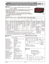
Autonics KN-2211W Digital Panel Meter User manual

Type
User manual
-|Transparent Guide|-
Follow instructions in ‘Cautions during Use’. Otherwise, it may cause unexpected
accidents.
For connecting the power, use the crimp terminal (M3.5, max. 7.2 mm)



use near the equipment which generates strong magnetic force or high frequency
noise.

disconnecting the power.
Use twisted pair wire for communication line.

󸠱
- Altitude Max. 2,000 m
- Pollution degree 2
- Installation category II
Cautions during Use
1-Channel Digital Temperature Indicators
KN-2000W Series
INSTRUCTION MANUAL
TCD210154AC

Read and understand the instruction manual and manual thoroughly before
using the product.
For your safety, read and follow the below safety considerations before using.
For your safety, read and follow the considerations written in the instruction
manual, other manuals and Autonics website.
󸠱
󸠱


Safety Considerations


 
01. Fail-safe device must be installed when using the unit with machinery that
may cause serious injury or substantial economic loss.(e.g. nuclear power
control, medical equipment, ships, vehicles, railways, aircraft, combustion
apparatus, safety equipment, crime/disaster prevention devices, etc.)
󸠱
02. 󸠳
high humidity, direct sunlight, radiant heat, vibration, impact or salinity
may be present.
󸠱
03. Install on a device panel to use.
󸠱
04. Do not connect, repair, or inspect the unit while connected to a power
source.
󸠱
05. Check ‘Connections’ before wiring.
󸠱
06. Do not disassemble or modify the unit.
󸠱
 
01. 󸠲
󸠱
02. Use a dry cloth to clean the unit, and do not use water or organic solvent.
󸠱
03. 󸠳
into the unit.
󸠱
04. Check the polarity of the measurement input before wiring.
󸠱
Product Components
󹌍 Product 󹌍 󹌍 󹌍 󹌍
Software
󸠱
DAQMaster
󹌍󹌍󹌍󹌍󹌍󹌕󹌍󹌍󹌍󹌍󹌍
󹌍󹌓󹌍󹌕
Comm. protocol 
 32 units
Synchronous method Asynchronous
Comm. method Two-wire half duplex
󸠱 recommended)
Comm. speed  (parameter)
Data bit 󸠱
Parity bit 󸠱
Stop bit 󸠱
Communication Interface
RS485
󸠲
Series KN-2000W Series
AC voltage DC voltage
Power supply  
Power consumption  
Sampling period • Thermocouple, 
󸠲 Refer to 'Input Type and Using Range'.
Digital
input
Contact 
Non contact 
󸠲 current 
Option
output
Alarm • 2󹌍󹌍
PV Transmission 
󹌍󹌕 
Display type 7 Segment (Red, Green, Yellow), LED type
Alarm output Hysteresis 
Relay
life
cycle
Mechanical • 2󹌍
• 4󹌍
Electrical • 2󹌍
• 4󹌍
Dielectric strength 

Vibration 
Y, Z direction for 2 hours
Insulation resistance 
Noise immunity 
Memory retention 
Ambient temperature 
Ambient humidity 
Approval 
Unit weight (packaged) 
Ordering Information

󸠱


0: No ( Option output:
Transmission is not

2: 2 alarm
4: 2 alarm

0: No

4: Communication
5: PV transmission +
Communication



Unit Descriptions
1
2
3
4
5
1. Display part(Red)
Run mode: Displays PV

Setting mode: Displays
parameter 󹌍󹌍.
2. Unit Indicator
Displays the set unit.
3. Alarm output indicator
󹌍󹌍󹌍󹌍󹌍󹌍
ON
4. [MODE] key

mode.


6. Selection switch for 󸠲
0 - 20 mA: Select it for DC 0 (4) - 20 mA input (default)
-1 - 10 V
RTD / TC / mV / ±1 V


Input Type and Using Range
Display accuracy
Input type Using temperature Display accuracy
Thermocouple
RTD
At room temperature



Out of room
temperature range 



Input type Display Using Using
Thermo-
couple
K (CA) TC-K - 200.0 to   to 
J (IC) TC-J - 200.0 to   to 
E (CR) TC-E - 200.0 to   to 
T (CC) TC-T - 200.0 to 400.0  to 752.0
R (PR) TC-R 0.0 to  32 to 
 TC-B 400.0 to  752 to 3272
 TC-S 0.0 to  32 to 
 TC-N - 200.0 to   to 2372
 TC-C 0 to 2300 32 to 
 TC-L - 200.0 to   to 
 TC-U - 200.0 to 400.0  to 752.0
 TC-P 0.0 to  32 to 2534
RTD
 Cu50 - 200.0 to 200.0  to 
 Cu10 - 200.0 to 200.0  to 
 JPt1 - 200.0 to   to 
 DPt5 - 200.0 to   to 
 DPt1 - 200.0 to   to 
Analog
Current 0.00 -20.00mA aMA1

( 
decimal point position.)
4.00 -20.00mA aMA2
Voltage
- 50.00 -50.00mV aMV1
- 200.0 -200.0mV aMV2
-
 - A-V1
 - A-V2
Connections

F.G.


0to20mA
 
Dimensions


 
 3
Panel cut-out

0

0


 



Bracket
󹌓󹌍󹌔󹌍󹌔󹌓󹌍󹌔󹌓󹌍󹌓󹌍󹌍󹌍󹌓󹌍
󹌗󹌗󹌖󹌖󹌖󹌗
-|Transparent Guide|-
Display Description Troubleshooting
BURN Flashes when input sensor is disconnected or
sensor is not connected. 
HHHH Flashes when PV is higher than input range. 
rated input range, this display
disappears.
LLLL Flashes when PV is lower than input range.
ERR  󹌍󹌍󹌍󹌍󹌍
󹌕
ERR1 Flashes when parameter and selection switch
󸠱 󸠱
Errors
Mode Setting
RUN
[MODE] Monitoring mode setting 
sec
RUN
 Program mode setting
 Digital input Auto
Supply the power with pressing
 Parameter reset Auto
Parameter Setting

other parameters. Refer to the descriptions of each item.

sec)



seconds.
Monitoring mode
Parameter Display Default Setting range Condition
 
temperature AL1 09(9 
 

alarm

AT2
 AL2 alarm
temperature AL2 09(9
 AL3 alarm
temperature AL3 00)1 [4 alarm output model]

 AL4 alarm
temperature AL4 00)1
 
display hPEK ----
󹌍󹌍󹌍)
󹌍󹌖󹌍󹌍󹌑
input)󹌍

sec from supplying the power.
󹌍

parameter
-
 
display lPEK ----
Program mode
Parameter Display Default Setting range Condition
 Input
󸠱 IN-P aMA2 Refer to 'Input Type and Using Range'. -
2-2 Temperature
unit UNIT ?C 

󸠱
Thermocouple,
RTD
2-3 Display unit dUNT ?/O 

󸠱
Analog
2-4 Low limit
Input L-RG 0$00 

2-5 
Input H-RG 2)00
 Decimal point dP )0 0.0, 0.00, 0.000, 0
2-7 Low limit scale L-SC 00)0 
 
scale H-SC 10)0 
 4 mA output
scale lOUT 00)0 [󹌍ransmission output model]
Input: Thermocouple, RTD:

Input: Analog


-
 20 mA output
scale hOUT 10)0

Input and
transmission
output
extension
ExI0 SP
[󹌍ransmission output model]
Setting
 Input range Transmission
output range
0P 󹌍 4 - 20 mA
5P extension 
 extension 

󸠱
Analog
 
operation
AL-1 AT!A

[Alarm output model]

AT0: 󸠰
 high limit alarm
AT2:  low limit alarm

-
 
option
A: Standard alarm

sequence
B: Alarm latch
D: Alarm latch and
 -


 AL2 alarm
operation AL-2 AT!A
[Alarm output model]

option
-
 AL2 alarm
option
 AL3 alarm
operation AL-3 AT@A
[4 alarm output model]

option
-
 AL3 alarm
option
 AL4 alarm
operation AL-4 AT@A
 AL4 alarm
option
2-20 Alarm output
hysteresis A-HY
001



alarm

AT2
 Input 󹌍
function InSF LIN LIN: Linear, ROOT: Root, SQAR: Square,
TUF: Two unit function -
2-22 Input
correction IN-B 0000  -
2-23 Input digital
󸠱 MAvF 04  -
2-24 Digital input
Terminal DI-T HOLD 
 -
2-25 Digital input
 DI-K HOLD
 Display color CLOR RED
Setting

Display part Color
󹌍 Error
RED Red Red
GRN Green Green
YELO Yellow Yellow
R--G Red Green
G--R Green Red
-
2-27 Alarm display
color 02) C-AL RRRR
[Alarm output model]
󹌍󹌍󹌍󹌕
R: Red, G: Green, Y: Yellow


AL-3: 
AL-4: 
Display color when alarm is ON -
 
alarm output BURN ON [Transmission output model]
 -
 Comm.
address ADRR 01 [Communication output model]
 -
2-30 Comm. speed BAUD (6K
[Communication output model]


-
 Comm. write COmY EnA [Communication output model]
EN.A: , DIS.A: 
2-32  LOC OFF
OFF
Program mode  (󹌍)
Monitoring mode 
rogram mode

Monitoring mode setting  (󹌍
only)
-



Communication Parameter Setting
󹌓󹌙󹌕󹌘󹌙󹌔
󹌓󹌙󹌕󹌘󹌙󹌔
Address Parameter Output range Condition
󹌍󹌑󹌒 󹌍
󹌗󹌍󹌓󹌍󹌗󹌍 󹌔
󹌍󹌑󹌒 󹌍
󹌍󹌑󹌒 󹌍
󹌍󹌑󹌒 󹌍
󹌍󹌑󹌒 󹌍
󹌍󹌑󹌒 󹌍
󹌍󹌑󹌒 󹌍
Address Parameter Output range Condition
󹌍󹌑󹌒 󹌍 󹌔󹌍󹌞󹌍 󹌔
󹌍󹌑󹌒 󹌍
󸠱
󹌍󹌍󹌐󹌍󸠱󹌍󹌍
󹌖󹌍󹌐 󹌔
󹌍󹌑󹌒 󹌍 󹌗󹌍󹌕󹌓󹌍󹌗󹌍󹌕󹌓󹌍󹌗󹌍󹌕󹌓󹌍󹌗󹌍
󹌕󹌓󹌍󹌗󹌍

󸠱
Analog
󹌍󹌑󹌒 󹌍 󹌍󹌞󹌍 󹌔
󹌍󹌑󹌒
󹌍󹌑󹌒 󹌔 󹌔
󹌍
󹌗󹌍󹌓󹌍󹌗󹌍 󹌔
󹌍
󹌍
󹌍
󹌍
󹌍
󹌍󹌍
󹌑󹌒
Program mode setting group󹌓󹌙󹌘󹌘󹌕󹌘󹌙󹌘󹌔
Address Parameter Display Setting range Condition
󹌍󹌑󹌒 󹌍󸠱 IN-P 󹌍󹌍󹌐󹌍󸠱󹌍
󹌍󹌖󹌍󹌐
󹌍
󹌍󹌍
󹌍
󹌍
condition
󹌍󹌑󹌒 Temperature unit UNIT 󹌗󹌍󹌓󹌍󹌗󹌍
󹌍󹌑󹌒 Display unit dUNT 󹌗󹌍󹌓󹌍󹌗󹌍󹌓󹌍󹌗󹌍󹌓󹌍󹌗󹌍
󹌍󹌑󹌒  H-RG 󹌍󹌍󹌍󹌍
󹌍󹌑󹌒 Low limit Input L-RG
󹌍󹌑󹌒  H-SC 󹌍󹌍󹌍󹌍
󹌍󹌑󹌒 Low limit scale L-SC
󹌍󹌑󹌒 Input correction IN-B 󹌍󹌍󹌍󹌍
󹌍󹌑󹌒 󸠱 MAvF 󹌍󹌍󹌍󹌍
󹌍󹌑󹌒 󹌍󹌍 AL-1 󹌗󹌍 h󹌍󹌍󹌍
󹌗󹌍 󹌍󹌍󹌍
󹌗󹌍󹌍󹌍󹌍
󹌗󹌍󹌍
󹌍󹌑󹌒 󹌍󹌍 AL-2
󹌍󹌑󹌒 󹌍󹌍 AL-3
󹌍󹌑󹌒 󹌍󹌍 AL-4
󹌍󹌑󹌒 󹌍󹌍 AL-1 󹌗󹌍󹌍
󹌗󹌍󹌍
󹌗󹌍󹌍
󹌗󹌍󹌍󹌍󹌍󹌍
sequence
󹌍󹌑󹌒 󹌍󹌍 AL-2
󹌍󹌑󹌒 󹌍󹌍 AL-3
󹌍󹌑󹌒 󹌍󹌍 AL-4
󹌍󹌑󹌒 Alarm output
hysteresis A-HY 󹌍󹌍󹌍󹌍
󹌍󹌑󹌒 20 mA output scale hOUT 󹌍󹌍󹌍󹌍
󹌍󹌑󹌒 4 mA output scale lOUT
󹌍󹌑󹌒 Decimal point dP 󹌗󹌍󹌕󹌓󹌍󹌗󹌍󹌕󹌓󹌍
󹌗󹌍󹌕󹌓󹌍󹌗󹌍󹌕󹌓󹌍󹌗󹌍
󹌍󹌑󹌒
Input and
transmission output
extension
ExI0 󹌗󹌍󹌓󹌍󹌗󹌍󹌓󹌍󹌗󹌍
󹌍󹌑󹌒 Digital input Terminal DI-T 󹌗󹌍󹌍󹌓󹌍󹌗󹌍󹌓󹌍
󹌗󹌍󹌔󹌍
󹌍󹌑󹌒  DI-K
󹌍󹌑󹌒 Input 󹌍 InSF 󹌗󹌍󹌓󹌍󹌗󹌍󹌓󹌍󹌗󹌍󹌓󹌍
󹌗󹌍󹌍󹌍
󹌍󹌑󹌒 
output BURN 󹌗󹌍󹌓󹌍󹌗󹌍
󹌍󹌑󹌒  LOC 󹌗󹌍󹌓󹌍󹌗󹌍󹌓󹌍󹌗󹌍
󹌍󹌑󹌒 Display color CLOR 󹌗󹌍󹌓󹌍󹌗󹌍󹌓󹌍󹌗󹌍󹌓󹌍
󹌗󹌍󹌔󹌓󹌍󹌗󹌍󹌔
󹌍󹌑󹌒 
C-AL 󹌗󹌍󹌓󹌍󹌗󹌍󹌓󹌍󹌗󹌍
󹌍󹌑󹌒 AL2 display color
󹌍󹌑󹌒 AL3 display color
󹌍󹌑󹌒 AL4 display color
󹌍󹌑󹌒 Comm. address ADRR 󹌍󹌍󹌍󹌍
󹌍󹌑󹌒 Comm. speed BAUD 󹌗󹌍󹌓󹌍󹌗󹌍󹌓󹌍󹌗󹌍󹌓󹌍
󹌗󹌍󹌓󹌍󹌗󹌍
󹌍󹌑󹌒 Comm. write COmY 󹌗󹌍󹌓󹌍󹌗󹌍
󹌍 󹌍󹌗󹌍󹌍󹌍󹌖󹌍󹌍󹌖󹌍󹌍
Address Parameter Display Setting range Condition
󹌍󹌑󹌒 
temperature AL1
󹌍󹌍󹌍󹌍󹌍
󹌍󹌍
󹌍
󹌍
condition
󹌍󹌑󹌒 AL2 alarm
temperature AL2
󹌍󹌑󹌒 AL3 alarm
temperature AL3
󹌍󹌑󹌒 AL4 alarm
temperature AL4
󹌍󹌑󹌒  hPEK 󹌍󹌍󹌍󹌍
󹌍󹌑󹌒  lPEK
Monitoring mode setting group󹌓󹌙󹌘󹌘󹌕󹌘󹌙󹌘󹌔
󹌍 󹌍󹌗󹌍󹌍󹌍󹌖󹌍󹌍󹌖󹌍󹌍
󸠲󹌘
󹌗 Display Value
Thermocouple
TC-K 0
TC-J
TC-E 2
TC-T 3
TC-R 4
TC-B 5
TC-S
TC-N 7
TC-C
TC-L
TC-U 
TC-P 
󹌗 Display Value
RTD
Cu50 
Cu10 
JPt1 
DPt5 
DPt1 
Analog
Current aMA1 
aMA2 
Voltage
aMV1 
aMV2 20
A-V1 
A-V2 22
  • Page 1 1
  • Page 2 2

Autonics KN-2211W Digital Panel Meter User manual

Type
User manual

Ask a question and I''ll find the answer in the document

Finding information in a document is now easier with AI