Single Display PID Temperature Controllers
TC Series
INSTRUCTION MANUAL
TCD220017AA
Thank you for choosing our Autonics product.
Read and understand the instruction manual and manual thoroughly before
using the product.
For your safety, read and follow the below safety considerations before using.
For your safety, read and follow the considerations written in the instruction
manual, other manuals and Autonics website.
Safety Considerations
• ion to avoid hazards.
• dicates caution due to special circumstances in which hazards may occur.
01. Fail-safe device must be installed when using the unit with machinery that
may cause serious injury or substantial economic loss.(e.g. nuclear power
control, medical equipment, ships, vehicles, railways, aircraft, combustion
apparatus, safety equipment, crime/disaster prevention devices, etc.)
02.
high humidity, direct sunlight, radiant heat, vibration, impact or salinity
may be present.
03. Install on a device panel to use.
04. Do not connect, repair, or inspect the unit while connected to a power
source.
05. Check ‘Connections’ before wiring.
06. Do not disassemble or modify the unit.
01. 2)
cable or over and tighten the terminal screw with a tightening torque of 0.74
to 0.90 N m.
a tightening torque of 0.74 to 0.90 N m.
failure.
02.
03. Use a dry cloth to clean the unit, and do not use water or organic solvent.
04.
into the unit.
Product Components
Product
Bracket
Sold Separately
•
• Terminal protection cover: RSA / RMA / RHA / RLA Cover
•
accidents.
•
extending wire.
• Keep away from high voltage lines or power lines to prevent inductive noise. In case
•
disconnecting the power.
•
controller.
•
•
•
• Make sure that power supply voltage reaches to the rated voltage within 2 sec after
supplying power.
•
•
- Pollution degree 2
- Installation category II
Cautions during Use
Ordering Information
S:
SP:
Y:
M:
H:
W:
L:
N: Indicator - without control output
R: Relay + SSR drive
N:
1: 1 alarm
2: 2 alarm
Series
Power supply
Power consumption
Sampling period
Refer to 'Input Type and Using Range'.
Control
output
Relay
SSR
Alarm output
Display type type
Control
type
Cooling
Hysteresis
Proportional band (P)
Integral time (I)
Derivative time (D)
Control cycle (T)
Manual reset
Relay life
cycle
Mechanical
Dielectric strength
Between input terminal and
Between input terminal and
Vibration
direction for 2 hours
Insulation resistance
Noise immunity
Memory retention
Ambient temperature
Ambient humidity
Insulation type
or reinforced
or reinforced
Approval
Unit weight (packaged)
Display Description Troubleshooting
OPEN Flashes when input sensor is disconnected or
sensor is not connected. Check input sensor status.
HHHH Flashes when PV is higher than input range. When input is within the rated input
LLLL Flashes when PV is lower than input range.
Errors
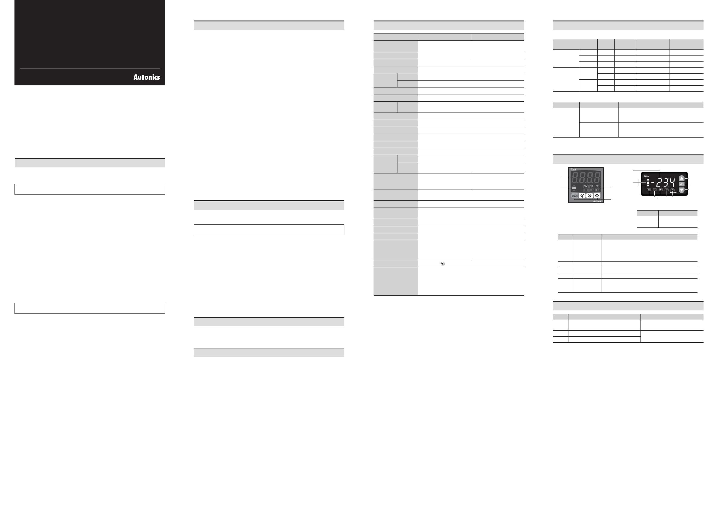
Unit Descriptions
1
22
3
1
2
2
3
1. Temperature Display part (Red)
•
• Settingname
setting value.
3. Input key
2. Indicator
Display Name
Mode key
Setting value control key
Display Name Description
deviation is over
deviation
deviation is under
Flashes during auto tuning every 1 sec
SV Setting value Turns ON when SV is displayed on temperature display part.
Temperature unit
AL1/2 Alarm output Turns ON when each alarm output is ON.
OUT Control output
Turns ON when control output is ON.
Input Type and Using Range
The setting range of some parameters is limited when using the decimal point display.
Input type Decimal
point Display
Thermo
-couple
1KCA to to
1JIC to -22 to
1LIC to to
1CUsH to to
CUsL to to
1DPtH to to
DPtL to to
Display accuracy
Input type Using temperature Display accuracy
Thermo
-couple
At room temperature
Out of room
temperature range
•


