Page is loading ...

Receiver
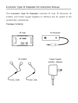
Emitter
Be sure the emitter is attached directly over the component’s IR receiver.
To locate the IR receiver, shine a flashlight into the unit and look for the
sensor.
How IR repeating works
AB-500
T
x
B
a
t
t
R
e
w
<
<P
la
y
>
F
F
>
>
L
e
a
r
n
S
t
o
p
P
a
u
s
e
1
2
3
4
5
6
7
8
9
0
P
o
w
e
r
-
/
-
-
C
h
Vo
l
L
e
a
r
n
E
r
r
o
r
A
ll
O
f
f
O
f
f
S
e
l
e
c
t
Tu
n
e
r
C
DS
a
t
V
C
R
D
V
DT
V
ChannelVision
TM
Point an
IR remote control
at the IR receiver
The IR receiver is wired to
the IR hub which routes the
signal to IR emitters
CD player
And the emitter
repeats the IR signal
in the other room.
IR Receiver
Model
P-1205
P
w
r
E
xpansion
G
lob
a
l
Zo
n
e
Z
o
n
e
G
l
o
b
a
l
Emitters
+
1
2
D
C
2
5
0
m
A
IR
R
e
c
e
iv
e
r
C
V
HANNEL
ISION
TM
+V
(white dash
or brown wire)
End view
ribbon cable
Ring
Tip
Collar
+V
Gnd
Sig
Typical IR receiver
connections (ref only)
IR receiver wire pinout
IR Receiver Specifications: (typical)
Specifications subject to change without notice.
*To extend wire, simply cut and splice in a longer 3-conductor wire (CAT5
will work). Be sure to follow the wiring configuration above.
Power Supply Voltage:
IR Frequency range supported:
*Max. wire distance from IR hub:
IR pickup range:
8-12VDC
30 kHz - 60 kHz
200 ft. (24 AWG)
40 ft. @ 38kHz, 25 ft. @ 56kHz
CHANNEL VISION
Limited Warranty
Channel Vision Technology will repair or replace any defect in material or
workmanship which occurs during normal use of this product with new or rebuilt
parts, free of charge in the USA, for two years from the date of original purchase.
This is a no hassle warranty with no mail in warranty card needed. This warranty
does not cover damages in shipment, failures caused by other products not
supplied by Channel Vision Technology, or failures due to accident, misuse,
abuse, or alteration of the equipment. This warranty is extended only to the
original purchaser, and a purchase receipt, invoice, or other proof of original
purchase date will be required before warranty repairs are provided.
Mail in service can be obtained during the warranty period by calling (800) 840-
0288 toll free. A Return Authorization number must be obtained in advance and
can be marked on the outside of the shipping carton.
This warranty gives you specific legal rights and you may have other rights
(which vary from state to state). If a problem with this product develops during or
after the warranty period, please contact Channel Vision Technology, your dealer
or any factory-authorized service center.
Swivel shade rotates to point toward a specific
area of the room for added rejection of optical
interference.
IR-2105 Stick-type IR receiver
(with adjustable field of view)
20
100
PC board slides in and out
for easy adjustment.
IR-2202 Tube-type IR receiver
(with adjustable field of view)
Tube diameter is 0.5”
IR-2400 2-piece mini IR receiver
2-piece design. Very small IR
sensor is all you see.
Create an IR system using your existing coax cable.
Power as many 8 IR receivers with one IR-4000.
Connect several IR emitters to a single
emitter output port.
Control two devices with a single emitter
output port.
34”
0.65”
0.35”
IR-2301 Table top IR receiver
G-IRBW J-IRBA J-IRBI,,&
+V (Ring)
Signal (Tip)
Ground (Collar)
Wiring for specific applications
Note: N.C = No Connection.
Application
IR Receiver
IR Emitter
Audio
Ring
+ Voltage
Ground
Ground
Right Sig.
N.C.
Ground
IR Signal
IR Signal
Left Sig.
Collar
Tip
Jack inserts to fit
Channel Vision wall plates.
Plasma-proof IR-Receivers
Simple, plug and play
IR receiver
All Channel Vision IR receivers are plasma-proof
and work with IR signals from 30kHz to 60kHz.
Quick connect cable included
Quick connect cable included
IR-Hubs and accessories IR-emitters
IR Receiver
M
odel
P-1205
Pwr
E
xp
an
sio
n
Global
Zone
Zone
Global
E
m
it
te
rs
+12DC
250mA
IR
Receiver
C
V
HANNEL
ISION
TM
IR-1200
Simple IR-Hub
IR-3003 Expandable IR Emitter
IR-3002 Dual Head IR Emitter
IR-4100
IR Coax Adaptor
IR-4000
IR Coax Engine
P-1205
Amplified IR-Hub
G-IRBW
Wall Plate Insert Connector
C-1201
IR-Receiver Termination Module
IR-on-coax
IR Receiver
Model
P-1205
P
w
r
Expansion
G
lo
ba
l
Zo
ne
Z
o
n
e
G
lo
b
a
l
Emitters
+
1
2
D
C
2
5
0
m
A
IR
R
e
c
e
iv
e
r
C
V
HANNEL
ISION
TM
CVHANNEL ISION
TM
Central
C-1201
CVHANNEL ISION
TM
Input
IR-4000
IR coax engine
To IR coax
adaptor
IR emitter
Pwr
CVHANNEL ISION
TM
From IR
engine
IR-4100
IR coax adaptor
To T V
IR receiver
500-127

Wiring Key
Signal
Ground
+V
CVHANNEL ISION
TM
Central
C-1201
IR1
IR BUS
POWER
-
S
+
-
S
+
-
S
+
-
S
+
-
S
+
-
S
+
-
S
+
-
S
+
-
S
+
-
+
IR2 IR3 IR4 IR5 IR6 IR7 IR8
IR
R
e
c
e
iv
e
r
Model
P-1205
Pwr
Expansion
Global
Zone
Zone
Global
Emitters
+12DC
IR
Receiver
C
V
HANNEL
ISION
TM
C
V
HANNEL
ISION
TM
CD player
Receiver
AB-500
T
x
B
a
t
t
R
e
w
<
<
P
la
y
>
F
F
>
>
L
e
a
r
n
S
t
o
p
P
a
us
e
1
2
3
4
5
6
7
8
9
0
Po
w
e
r
-/--
C
h
V
o
l
Lea
r
n
E
rror
A
l
l
O
ff
O
f
f
S
e
le
c
t
Tu
n
e
r
C
D
S
a
t
V
C
R
D
VD
T
V
Channel Vision
TM
IR-2105
IR-2202
IR-2301
IR-2301
IR-2400
Connect up to
8 IR receivers
IR receiver
(IR-2105 shown for reference only)
IR emitter
(IR-3003 shown for reference only)
12 VDC
Power supply
IR-1200
Receiver
Emitter
If your coax IR system is not
working, check to see if the
IR engine is feeding
approximately 12 Volts DC
onto the coax between the
shield and center pin. (Any
voltage between 8-12VDC is
OK). If there is no voltage
between the center pin and
shield, check the connectors
on each end of the coax.
If you are trouble shooting a whole-house IR system and you measure
approximately 8-12 Volts DC on the output of the IR engine, but 0 Volts DC
on the output of your RF splitter, check the following items:
1. Make sure you are using a DC passing splitter. Traditional splitters will
short out DC voltage traveling on the coax and prevent your IR system
from working.
2. Make sure that there are DC blocks (model 3109) on any output from the
RF splitter that will not be connected to an IR-4100. If outputs from the
splitter are connected directly to TV sets without going through a IR-
4100 or DC block, the system voltage will be shorted out by the input of
the TV set.
3. Double check the fittings at the end of your coax cables. If a little bit of
shielding is touching the center pin, the voltage will be shorted out and
the system will not work.
Don’t worry. The IR-4000 engine has a current limiting circuit. If the engine
is shorted (due to a bad connection or a non-DC passing splitter)
nothing will be harmed.
If your IR system is not working:
1. Try using your remote control directly on the source component (without using
IR repeating). Make sure there’s not a simple problem such as week batteries
in the remote control.
2. Try controlling a different device to see if the problem only occurs when
attempting to control a specific device. There are some devices that use
unusual IR frequencies that these IR receivers cannot detect.
3. Make sure you have positioned the IR emitter over the IR sensor on your
equipment. It may be difficult to locate; you may find it helpful to have another
person use the remote through one of the IR receivers while you slowly move
the IR emitter across the face of the component, when you are directly over
the IR sensor, your equipment should respond to the IR signals from the
emitter. Use the provided double stick tape to attach the emitter to your
equipment at that location.
4. Sometimes signals from the IR emitter can be too strong for the sensor in your
component. If you suspect this, hold the emitter a few inches away from your
component and see if it responds. If it does, you can place an extra piece of
foam tape (which is provided for attaching the emitter) directly over the
emitters LED. This will attenuate the signal and solve the problem.
Troubleshooting Coax IR systemsGeneral Troubleshooting for IR Systems
CV
HANNEL ISION
TM
Input
IR-4000
IR coax engine
To IR coax
adaptor
IR emitter
Pwr
VDC
A basic IR system, like the one shown below, is often used when an
audio/video signal is distributed to a remote TV location using an RF
modulator. The IR-4100 is located near the TV, providing a connection for
an IR receiver, and the IR-4000 is located near the audio/video source,
providing an IR emitter output.
The IR-1200 Simple IR hub is perfect for small IR systems
that only require a single IR receiver and emitter.
A
B
-5
0
0
T
x
B
a
t
t
R
e
w
<
<
P
l
a
y
>
F
F
>
>
L
e
a
r
n
S
to
p
P
a
u
s
e
1
2
3
4
5
6
7
89
0
P
o
w
e
r
-
/
--
C
h
Vo
l
L
e
a
r
n
E
rr
o
r
A
ll
O
f
f
O
f
fS
e
le
c
t
T
u
n
e
r
C
D
S
a
t
V
C
R
D
V
D
T
V
C
h
a
n
n
e
l
V
is
io
n
T
M
CVHANNEL ISION
TM
From IR
engine
IR-4100
IR coax adaptor
To TV
IR receiver
CVHANNEL ISION
TM
Input
IR-4000
IR coax engine
To IR coax
adaptor
IR emitter
Pwr
DVD player
CHANNEL VISION
TM
E 2002
A
B
E Series
Basic IR-on-coax Setup
Simple system
A
B
-5
00
Tx
B
a
tt
R
ew
<<
Pl
a
y
>
F
F
>
>
Le
a
r
n
S
t
o
p
P
au
s
e
1
2
3
4
5
6
7
8
9
0
P
o
w
er
-
/
-
-
C
h
Vo
l
L
e
a
r
n
E
r
r
o
r
Al
l
O
ff
O
ff
S
e
le
c
t
Tu
n
er
C
D
S
at
V
CR
D
V
D
TV
C
h
a
n
n
e
l
V
i
s
i
o
n
T
M
Part No. HS-2
-WAY SPLITTER/COMBINER2
5MHz-1GHz All Port DC passing
CVHANNEL ISION
TM
IN
/out
OUT/in
OUT/in
A
B
-5
0
0
T
x
B
a
t
t
R
e
w
<
<
P
l
a
y
>
F
F
>
>
L
e
a
r
n
S
t
o
p
P
a
u
s
e
1
2
3
4
5
6
7
8
9
0
P
o
w
e
r
-/
-
-
C
h
Vo
l
L
e
a
r
n
E
r
r
o
r
A
l
l
O
f
f
O
ff
S
e
le
c
t
Tu
n
e
r
C
D
S
a
t
V
C
R
D
V
D
T
V
C
h
a
n
n
e
l
V
i
s
i
o
n
T
M
CVHANNEL ISION
TM
From IR
engine
IR-4100
IR coax adaptor
To TV
IR receiver
CVHANNEL ISION
TM
Input
IR-4000
IR coax engine
To IR coax
adaptor
IR emitter
Pwr
DVD player
CVHANNEL ISION
TM
From IR
engine
IR-4100
IR coax adaptor
To TV
IR receiver
CHANNEL VISION
TM
E 2002
A
B
ESeries
Part No. HS-4
-WAY SPLITTER/COMBINER4
5MHz-1GHz All Port DC passing
CVHANNEL ISION
TM
IN
/outOUT/in OUT/in
OUT/inOUT/in
DC Block
DC Block
In from CATV service
DC Block and
75 ohm terminator
HS-4
DC Passing
splitter
Joining your Modulator with CATVConnecting multiple receivers to a single hub
Zoned IR system
IR Receiver
Model
P-1205
Pwr
Expansion
Global
Zone
Zone
Global
Em
itters
+12DC
IR
Receiver
C
V
HANNEL
ISION
TM
C
V
HANNEL
ISION
TM
IR Receiver
Model
P-1205
Pwr
Expansion
Global
Zone
Zone
Global
Em
itters
+12DC
IR
Receiver
C
V
HANNEL
ISION
TM
C
V
HANNEL
ISION
TM
Sat radio
DVD player
Sat radio
DVD player
Receiver
Zone A
(Bedroom 1)
Zone A devices
Zone B devices
Global device
Zone B
(Bedroom 2)
Only 1 power supply
is needed.
Only 1 power supply
is needed.
Only 1 power
supply is needed.
The diagram shown here, will create 2 IR zones that will allow for independent control
of identical devices from the same manufacturer. The ‘Zone’ IR emitters will only
respond to signals from the IR receiver that is in the same zone. The ‘Global’ IR
emitters will respond to signals from any IR receiver in the system.
IR systems may include several different styles of IR receivers depending on
the specific application in each room. The C-1201 joins all the signals from
the IR receivers and outputs the to the P-1205.
/