Page is loading ...

1-
L
o
-
a
g
?
-
I
(J
=
l-
ru
l-
o
AUrilDilril@
ft{ltl
coMMUNICATIONSPTYLTD
sA60-3
^L^
t
&
sA120-4
Mixer
Amplifiers
A
AISTRA1IAN MADE
3
OrCih,
Erdor-fr
ffi
Audio
Telex Communications Pty
Ltd
ACN
001345482
lncorporated ln NSW
NSW & ACT
QLD
& NT
vlc
149 Beaconsfleld
Street
Private
Bag
149
Sllvenrater NSW 2128
Australla
Ph 02 96r'7 1411
Fax 02 9648 3698
42 CommerclalRoad
PO Box 871
Fortitude
Valley
QLD
4006
Ph 07 3852 1312
Fax 07 32521237
22127 7 M lddleborough Road
Box
HillVlC
3128
PO
Box
151
Blackburn South VIC
3130
Ph 03 98907477
Fax 03 9890 7977
WA SA TAS
7164-66 Kent Street
PO Box
489
Cannington WA
6107
Ph 08 9356 2761
Fax 08 93562762
Electronlc Concepts Pty Ltd
76 George Street
Thebarton SA 5031
PO Box 7034 Hutt Street
Adelalde SA 5000
Ph 08 82349444
Fax 08 823/ 94'/1
K W McCulloch Pty Ltd
54a
Albert Road
iloonahTAs 7009
Ph
03 6228
6373
Fax 03 6278 1063
New Zealand
Unlt B,11
Plermark Drive
PO Box 512
Albany
NZ 1331
Ph 09
4159426
Fax 09 415 9864

5A60-3 Mixer
Amplifier
SAI 2O-4
Mixer Amplifier
Product
DescripUon
The 5460-3 is
a
60 watt, 6 channel mixer
amplifier
and
similarly
the SAl20-4
is a 120 uatt,
6 channel mixer amplifier.
Both
models op€rate
fim
240
VAC
@
50 Hz
(r
I l0 VAC
@
60llzwith
factory modification)
u 24
VDC
via
an efiernal bottery
supply
and both
can either
be desk or rack momted.
Bo{h
are 2 standard rack
units high
and standard
rack
width
of 482mm,
fu
table
mounting rubber
feet
are sryplied but
these
should be
removed
if
rack mounting is intended.
Both
amplifiers will
deliva
their
sp€cified wattage
into
loads of
4 or 8 ohms,
70 m
100
volt
line. Both
models
feature
six dual
purpose
inputs,
)(LR balanced
mic
input
and
dual
RCA
aux/line
level inprrts.
Channel 6 only
has a higher level
aux/line lerrcl
input to enable
it to accept
a
CD
player
m similar
high lwel inpr$s.
The SA
series
f€ature
outprs overload
protec'tim,
a TRS insert
point
betrreen the
mixer and
amplifier
stages fm
easy insertior
of
a
graphic
EQ, fBX Feedback
Exterminator
or similar,
internal
heat
sinking
and a strmg
steel chassis.
Front
Panel Controls
aaaaar
Du{
ticrophonelline
Gain
Controls! The
6 dual
mic/line input
controls
are marked
Ch
I
througlr
Ch 6
and
shanld
be adjuSed
to
provide
the
required
mix level ftr
each individual
channel.
Start
with
the controls set
to level
0 and turn
the cryrtrols
slowty
clockwise
until the desirod
mix for
eadr
channel is ohained.
Bass
Tonal
Control:
Setting
this
csrfol in
the cenfe
"zero"
pcition
will
give
an
overall
flat
bass
response
to the
otttput of the amplifier.
A-dju$ing
the
bass
control
in
a clockwise direction
will
provide
up to
+12
dB of bass boost
@
100
tlz.
Adjusting
the
hss
cmtrol
in a cormter-clockwise
direction
will
provide
up to
-12
dB
of hss ctft
@
lO0IIz.
Treble Tonal
GontrOl:
Setting this
control
in the
ce,ntro
"z6d'
positior
will
give
an overall
flat treble respmse
to
the
output of the
amplifier. Adjusting
the
treble
control in
a clockwise
direction will
provide
up
to
+9
dB of treble
boosf
@
l0 klft.
Adjusting
the beble
cmtrol
in a
cotmter-clockwise
directiod
will
provide
up
-9
dB of
treble cut
at
l0
ktlz.
llaster
Output
Control:
This cmtrol
adjusts the overall
output
level
of the amplific
depending
m the levels
set
for
the
individual
input
mix
channels
as
detailcd
above. Staxt with
the control level
set to level
0 and slowly
turn the
control
clmkwise
until fie
desired
ortput
lernel
ofthe
amplifier
is reached.
POWef
SWitCh: This switch
contols
the
switctring of
the
AC
power
to the
amplifier.
Rocking
ttris
switch trpwards
turns
on AC
power
to
the amplifier
while rocking
the
witch dovmwards
turns
power
offto
the amplifier.
When in the
upunard
"On'
position,
the red
nesr in
the body
of
the
switch will
gloril.
LED
Display
VU
ileter:
Marked
in
decibel
graduations
frm
-21
dB to
+3
dB, the light
enitting
diodea
will
indicate
ths vslrrme
level
at the
output
of
the
arnplifier.
Fu
ncmal operation
the LED's
glow
green
* *t"y
modulate with
the
output
level
of the
amplifier.
If the lights
are
consistently
indicating
red
the
amplifier is
being overdriven, resulting
in
distontior in
the
qualrty
of the audio
sigrral.
l.
4.
5.

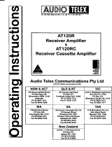
Rear Panel Connections
t.
3 Pin IEC
AC
ilains
PoWer
lnlet The
operating
voltage is
240 VAC
@
50 ttzor n0
VAC
@
60 ttz. The
AC
power
voltage
is not
externally
user
adjustable
but
is
factory
preset.
The
inlet is
equipped
with an inbuilt
AC
ftse holder
fitted
with
a 4
amp slow
blow fuse
plus
one
spare. Power
consumption
is 350 watts.
I
Phase
ensure
that
the mains
power
cord
is
disconnected
before
attempting
to
check
or
replace
this frse.
z.
Direct
Output
Connections:
These
screw
tenninals
allow
access to the
direct
outputs of the
amplifier.
2
spare
screw
terminals
allou'
for the
connection
of various
tone module
accessories.
Reading from
left to right
the terminals
are.
o
Lowlmpedance
Cmmon
o
4 Ohms
o
8
Ohms
r
Con$ant
Voltage
Comnm
o
70 Volt Line
r
100
Volt
Line
.
Spare
'
SPare
Note:
The
minimum
impedance
level
at any
timc
on
maximum
load
fc
100 Volt
line
should be no less
than
80
Ohms fm
the
SAl20 and
no
le.ss
than
170
Ohms fm
the 5.{60.
3.
24
Volts
DC
Power
Source
Connection: Two
pst
style
terminals
atlow
for
the connection
of
an ortemal
24
VDC
battery for
applicaticrs
where
PA
system
operation
is imperative.
The red
terminal
post
is for
cmnectisr
to the
positive
(+)
tominal.
The
black
terminal
pct
is for
connection
to
the negative
(-)
terminal.
A
trickle
charge
circuit
provides
a
maximum
300mV
autmatically
to a stand-by
battery
connected to
the
24
VDC input
on the
SAl20
only.
4'
DC
Fuse
Holder: Remove
with
a screwdriver
if
access is required.
DC
fuse rating
is 10 Amps
Slow Blow
fc the
SAl20
and 5
Amps
Slow Blorv fo
the
5,{60.
S.
lnSeft
TRS phmo
socket
insert
point
(6.5mm).
Enables
a
graphic
equaliser, FBX
Feedback
Exterminator
or
similar
product
to be connected'
Ilnbalanced
insertion,
bneaks normal
connection
between the
pr+amp
and
power
amp stages
of the
amplifier.
Tip
=
Return.
Ring
= Send.
Sleeve:
Grormd.
O'
Tape
Output
2
x RCA
style
phuro
cnrtput cmnectu fon
line level
output. hovides
a maximrn
of 350mV into
10K
Ohms,
ideal fu
a
connection
to most
standard
tape recuders.
This
output is
sonced
before the
mast€r
gain
comtol
and
as such,
the tape
output
level
is
not
influenced
by the
operation
of the master
gain
cmfrol.
Z.
Line
OUtpUt
Male )(LR
style
balanced
transformer
isolated output fm
connection
to
additional
power
amplifiers.
hovides
a maximum
of
700mV
Suitable
for driving
power
amplifiers
or
similar
devices.
Pin connections
are
pin
I
:
Earth.
Pin
2
:
Active Positive (+).
Pin
3
:
Active
Negative
O.
S-
Line
lnpUtS: Note:
AII
inputs lre
universet
line
/ microphone
inpub.
Bot'h
connectors
cen not
be utitised
for
rny one
input
Six
pairs
of RCA
style
phoro
input
connectors
acc€pt
rmbalanced
line
or
auxiliary inputs for
charnels
I through
6.
Channel
6 accepts higher
level
inputs
such as
a CD
player.
l.
ilicrophOne
lnpUts: Note:
All
inputs
are
universat line
/ microphone
inputs
Bott
connectors
cen not
be utilised
for
any
one
input
Six
ferrale XLR
inputs
acc€pt
200 Ohrn
balanced
or unbalanced
microphone
inputs.
Pin
connec*ions
are
pin
I
=
Earth.
Pmz: Active
Positive
(+).
Pin 3
:
Active
Negative
C).
auSts
sAt20-a I sl60-!
^c
5^
s/81^c 2^ s,/8
Dc
lo^
s,/sloc aa
s,/E
Lht 5 Lltt
5 LtNt 4
ooo
'b''b'b'
ooo
ttc5
ltc5 ltca
!c!
rlc2
lrcl
O7- O7-
O--\
.r-\
g^
i.
oj
c
oi
,c
o
:c
oi
ic
o)
:c
o.
\
a
'
a
/
o
'
c
/
\
c /' c
.eoca,c
va
va
La

Special Facilities
Phantom
PoWer: Normally
supplied
to each
of
the six XLR microphure inputs. Provides
18 Volts DC.
An
internal
on/off
slide
switch can
be fomd on the internal
circuit
board
PCB6I77
to
disconnect
phantm power
from all six
inputs
g
It
is
neces$ry
to disconnect
the
power
cord
end remove
the
lid
from the amplificr
beforc
opcreting
this switch.
Umlting: The
SA series
of amplifiers
are equip'ped with
a
"soft
knee limitet'',
wtrich
prctects
the
emplifier
fim
overload
c
short circuits.
ln sme
cases it may
be necessary
to disconnect
the
limiter
to obtain higlrer than rated rxrlver. This
can be
achieved
by
re,noving
a link sr PCB6I79.
Perfuming
this
procedure
can void any warranty
claim.
I
It is necessary to
disconnect
the
trxlwer
cord end remove
the lid from
thc
amplifier before attempting
this
procedure.
Optional Accessories
g
The
instellation
of mme
of the following
optionel
aceessories involves
rccess to the inside of thc
amplifier. Instaltation
should only
be attcmpted
by r
qurlified
technicien. Always
turn off the
AC
Flwer
rnd
remove the AC
Fwer
cord beforc
attempting
to
sccoss the inside
of the emplifier.
Pleese contlet
your
nearest Audio Tclex of;fice for
details of
your
neerest
quelificd
technician.
TOne GenefatOfS: Forn
separate tmes
are available
as
an
optiol
via the
ATC5488
ture
generatc
board.
This internally
mounted
PCB
is easily
fitted
and
plugs
directly
into
a socka
prwided
on the internal circuit
board
PCB6I78.
Please
follow the
instructions
zupplied with
the tone
generatm.
When any tme from the
ATC5488
PCB
is activated all inputs will
autmatically
mute
exept
fm input
ore.
Tsres available
m the
ATC5488
tsre
generatr
board are:
Evacuatim
Tore
(to
Ausralian
Standard
A32220.1.2)
Alert
Tone
(to
Australian
Standard
A5222A.1.2)
Bell Tme
heAnnotmce
Chime
Voice Opefated
tuting llodules:
Two separate models
are available for the SA
series amplifiers. They
are easily
fiued
internally.
Bdh
plug
directly into
a socke
provided
on
the internal circuit board
PCB6I78.
The
models
are:
TX3014 Mtfing
Module with
Priority- Provides
two levels
of muting with
priuity
for
channel
one,
wtrich
mutes all odrer inputs
and scmdry
primity
for channel
two, wlrich
mutes all other inputs except
for channel one.
TX30l0
Muting
Module- Provides
single muting from
channel ure only. When
activated all other
channsls are
muted.
Fuse
Sizes SA120 Amplifier
tains
240
VAC: 5
Amperes
SlowBlow
DC:
l0Amperes SlowBlow
Fuse
Sizes SA60 Amplifier
Ilains 240
VAG:
2
Amperes
SlowBlow
DG: S Amperes SlowBlow
/