
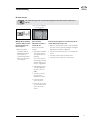
Troubleshooting guide
Gecko Alliance
450 des Canetons, Quebec City (Qc), G2E 5W6 Canada, 1.800.78.GECKO
www.geckoalliance.com
Printed in Canada
9919-101313-A
Rev. 11-2015
© Groupe Gecko Alliance inc., 2015
All trademarks or registered trademarks
are the property of their respective owners.
Y series and in.xe
Possible error codes
Error code explanation
Step by step troubleshooting


1
Warning .......................................................................................................................................................................... 2
Troubleshooting .............................................................................................................................................................. 3
- Possible error codes on in.yj, in.ye, in.yt and in.xe control systems .................................................................. 3
- Hr error message ............................................................................................................................................... 4
- HL error message .............................................................................................................................................. 5
- Prr error message .............................................................................................................................................. 8
- FLO error message ............................................................................................................................................ 9
- UPL error message .......................................................................................................................................... 10
- AOH error message .......................................................................................................................................... 10
- OH error message ............................................................................................................................................ 11
- Pump 1, 2, 3, 4, 5 or the blower is not working ................................................................................................ 12
- The circulation pump is not working ................................................................................................................ 16
- The ozonator is not working .............................................................................................................................. 16
- Nothing seems to be working (North American models) .................................................................................. 17
- Nothing seems to be working (CE/AUS/NZ models) or (European models) ..................................................... 19
- The spa is not heating ...................................................................................................................................... 21
- The keypad does not seem to work .................................................................................................................. 23
- GFCI/RCD trips ................................................................................................................................................. 24
Table of contents

2
WARNINGS:
Before installing or connecting the unit, please read the following.
* FOR UNITS FOR USE IN OTHER THAN SINGLE-FAMILY DWELLINGS, A CLEARLY LABELED EMERGENCY SWITCH SHALL
BE PROVIDED AS PART OF THE INSTALLATION. THE SWITCH SHALL BE READILY ACCESSIBLE TO THE OCCUPANTS AND
SHALL BE INSTALLED AT LEAST 5' (1.52 M) AWAY, ADJACENT TO, AND WITHIN SIGHT OF THE UNIT.
* ANY DAMAGED CABLE MUST BE IMMEDIATELY REPLACED BY QUALIFIED PERSONNEL.
* TURN POWER OFF BEFORE SERVICING OR MODIFYING ANY CABLE CONNECTIONS IN THIS UNIT.
* TO PREVENT ELECTRIC SHOCK HAZARD AND/OR WATER DAMAGE TO THIS CONTROL,
ALL UNUSED BUSHING CONDUITS MUST BE PLUGGED WITH THE ATTACHED NIPPLE.
* THIS CONTROLLER MUST NOT BE INSTALLED IN PROXIMITY OF HIGHLY FLAMMABLE MATERIALS.
* LOW SUPPLY VOLTAGE OR IMPROPER WIRING MAY CAUSE DAMAGE TO THIS CONTROL SYSTEM.
READ AND FOLLOW ALL WIRING INSTRUCTIONS WHEN CONNECTING TO POWER SUPPLY.
* THIS PACK CONTAINS NO USER SERVICEABLE PARTS. CONTACT AN AUTHORIZED SERVICE CENTER
FOR SERVICE.
* ALL CONNECTIONS MUST BE MADE BY A QUALIFIED ELECTRICIAN IN ACCORDANCE WITH
THE NATIONAL ELECTRICAL CODE AND ANY STATE, PROVINCIAL OR LOCAL ELECTRICAL CODE
IN EFFECT AT THE TIME OF THE INSTALLATION.
* PRODUCT MUST BE DISPOSED OF SEPARATELY IN ACCORDANCE WITH LOCAL WASTE DISPOSAL LEGISLATION.
* THIS APPLIANCE IS NOT INTENDED FOR USE BY PERSONS (INCLUDING CHILDREN) WITH REDUCED PHYSICAL,
SENSORY OR MENTAL CAPABILITIES, OR LACK OF EXPERIENCE AND KNOWLEDGE, UNLESS THEY HAVE BEEN GIVEN
SUPERVISION OR INSTRUCTION CONCERNING USE OF THE APPLIANCE BY A PERSON RESPONSIBLE FOR THEIR
SAFETY.
* CHILDREN SHOULD BE SUPERVISED TO ENSURE THAT THEY DO NOT PLAY WITH THE APPLIANCE.
* MEANS FOR DISCONNECTION MUST BE INCORPORATED IN THE FIXED WIRING IN ACCORDANCE WITH
THE WIRING RULES.
* CAUTION: IN ORDER TO AVOID A HAZARD DUE TO INADVERTENT RESETTING OF THE THERMAL CUT-OUT, THIS
APPLIANCE MUST NOT BE SUPPLIED THROUGH AN EXTERNAL SWITCHING DEVICE, SUCH AS A TIMER,
OR CONNECTED TO A CIRCUIT THAT IS REGULARLY SWITCHED ON AND OFF BY THE UTILITY.
* PARTS CONTAINING LIVE PARTS, EXCEPT PARTS SUPPLIED WITH SAFETY EXTRA-LOW VOLTAGE NOT EXCEEDING 12
V, MUST BE INACCESSIBLE TO A PERSON IN THE BATH OR SPA.
* PARTS INCORPORATING ELECTRICAL COMPONENTS, EXCEPT REMOTE CONTROL DEVICES, MUST BE LOCATED OR
FIXED SO THAT THEY CANNOT FALL INTO THE BATH OR SPA.
* PARTS ARE TO BE INSTALLED IN THE CORRECT ZONE AND EQUIPOTENTIAL BONDING CARRIED-OUT IN
ACCORDANCE WITH THE WIRING RULES.
*CLEARANCE AND MINIMUM DISTANCE BETWEEN THE VARIOUS PARTS OF THE APPLIANCE AND THE SURROUNDING
STRUCTURE ARE NOT SPECIFIED AS LONG AS THEY ARE SUFFICIENT SO THAT THE AMBIENT TEMPERATURE
AROUND THE CONTROLLER DOES NOT EXCEED 60°C
Aeware
®
, Gecko
®
, and their respective logos are Registered Trademarks of Gecko Alliance Group.
in.yj™, in.keys™, in.touch™, in.k200™, in.k400™, in.k450™, in.k600™, K-19™, K-35™, K-8™, in.k1000™, in.k800™, in.k500™,
in.k300™, in.flo™, in.put™, in.seal™, in.link™, in.t.cip™, in.stik™, heat.wav™, Y Series™, and their respective logos are Trademarks
of Gecko Alliance Group.
All other product or company names that may be mentioned in this publication are tradenames, trademarks or registered trademarks of
their respective owners.
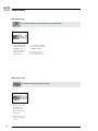
Warning

3
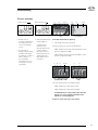
The error codes indicate a failure or problem that must be rectified to guarantee the good function of the system.
The error code and the water temperature are displayed alternately on the keypad.
The error messages listed below display on the LCD and LED keypads. If your spa is equipped with a color keypad,
please refer your techbook for more information on error messages.
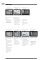
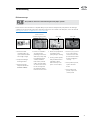
FLO
The system has detected no water flow during the main
pumps operation.
UPL
No low-level configuration is present in the control system
memory, insert a valid in.stik to program the control unit.
OH
The spas water temperature has reached 108°F (42°C)
Do not enter spa water!
AOH
The temperature inside the spa skirt is too high and
causes an increase of the internal temperature of the
control system above normal limits.
Possible error codes on in.yj, in.ye, in.yt and in.xe control systems
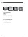
Troubleshooting
HL
The water temperature in the water heater has reached
119 °F (48°C).
Do not enter spa water!
Prr
The system detects a problem with the regulation probe.
The system constantly verifies if the temperatures read by
the probe are inside the normal limits.
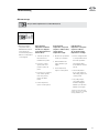
Hr
An internal error with the system hardware has been
detected.

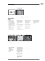
4
An internal error with the hardware was detected.
• First,restartthespa
system, then, start and
stop all pumps and
blowers.
• Iftheerrorcomesback,
replace the control
system.
Hr error message
Troubleshooting

5
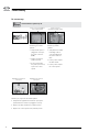
The system has stopped because the water temperature in the water heater reached 119 °F
(48 °C).
Warning! Do the following
operations with precaution
the water heater's body
may be very hot.
• Measurethewater
temperature with an
DIGITAL thermometer
and compare the
measured temperature
with the one displayed
on the keypad.
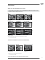
HL error message
Troubleshooting
If the measured temperature is below 119 °F (48°C)
and the water heater's body is hot:
• Withcare,verifythewaterheater'sbodytemperature.
If it is hot, assure yourself that nothing is blocking the
water flow (closed valves or dirty filter).
• Turnthespaoffandturnitbackontoreinitialisethe
system.
• IferrorHLpersistsreplacethewaterheater.
• IferrorHLpersistsreplacethecontrolsystem.
If the measured
temperature is inferior to
119 °F (48 °C):
For the in.yj-re control
systems:
• Verifythattheregulation
and overheat probe is
correctly placed in the
plumbing.
If it is, assure yourself
that nothing is blocking
the water flow (closed
valves or clogged filter).
• Verifythattheprobeis
correctly plugged into
the probe connector
(P40).
• Turnthespaoffand
turn it back on to
reinitialise the system.
• IferrorHLpersists
replace the probe.
• IferrorHLpersistsafter
the probe replacement,
replace the control
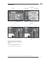
system.
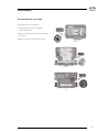
Probe connector (regulation
and overheat captor)
in.yj-re

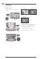
6
For the in.yj control
systems:
• Verifythatthe
heat.wav low voltage
cable is correctly
plugged into the
probe connector (P1).
If the measured temperature is below 119 °F (48°C) and the water heater’s body is not hot:
Probe connector
(heat.wav low voltage cable)
Regulation and overheat
captor probe
Regulation and overheat
captor probe
Troubleshooting
Regulation and overheat
captor probe
Regulation and overheat
captor probe
For the in.ye, in.yt and
in.xe control systems:
• Verifythattheregulation
and overheat captor are
plugged in correctly.
• Turnthespaoffand
turn it back on to
reinitialise the system.
• IferrorHLpersists
replace the water
heater.
• IferrorHLpersists
replace the control
system.
in.yj
in.yjin.yj-re
in.ye and in.yt
in.ye and in.yt
in.xe
in.xe
If the measured temperature is 119 °F (48°C) or above and does not correspond to the one displayed on the keypad:
For the in.ye, in.yt and
in.xe control systems:
• Verifythattheregulation
and overheat captor are
plugged in correctly.
• Ifthecableiscorrectly
plugged in, replace the
water heater.
• Turnthespaoffand
turn it back on to
reinitialise the system.
• IferrorHLpersists
replace the control
system.
For the in.yj control
systems:
• Verifythatthe
heat.wav low voltage
cable is correctly
plugged into the probe
connector (P1).
For the in.yj-re control
systems:
• Verifythattheprobeis
correctly plugged into
the probe connector
(P40).
• Ifthecableiscorrectly
plugged in, replace the
probe.
• Turnthespaoffand
turn it back on to
reinitialise the system.
• IferrorHLpersists
replace the control
system.
Probe connector
(heat.wav low voltage cable)
Probe connector (regulation
and overheat captor)

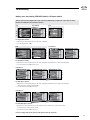
7
If the measured
temperature is 119 °F
(48°C) or above and the
exterior temperature is
very high:
• Takeofthespalid
(even for the night).
• Starttheblowersifthe
spa is equipped with it.
• Waitthatthespacools
down (add cold water if
needed).
• Turnthespaoffand
turn it back on to
reinitialise the system.
L1 GroundN L1 GroundN
• Usethevoltmeteronthe
water heater’s terminal
block to measure the
tension between the line
(L1) and the ground.
• Ifyoumeasure120V
or 240 V, replace the
control system.
• Ifyoudonotmeasure
120 V or 240 V, the
pump may be heating
the water excessively
during the filtration
cycle.
If the measured temperature is 119 °F (48°C) or above and the exterior temperature
is not the cause:
For the in.yj, in.ye, in.yt and in.xe control systems:
Troubleshooting
L2
Ground
L1N
If the measured temperature is 119 °F (48°C) or above
and the exterior temperature is not the cause:
For the in.yj-re control systems:
in.yj in.ye and in.yt in.xe
• Verifythattheprobeis
correctly plugged into
the probe connector
(P40).
• Settheconsignedvalue
to a temperature lower
than the actual water
temperature.
The water heater
indicator should turn off.
• Turnoffallthepumps.
If a pump is still
running, replace the
control system.
• Turnthespaoffand
turn it back on to
reinitialise the system.
• IferrorHLpersists
replace the probe.
• Settheconsignedvalue
to a temperature lower
than the actual water
temperature.
The water heater
indicator should
turn off.
in.yj-re
• Reducethelengthofthe
filtration cycle.
• Turnthespaoffandturn
it back on.
Probe connector (regulation
and overheat captor)
• IferrorHLpersistsafter
the probe replacement,
replace the control
system.

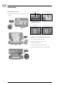
8
in.yj-re
For the in.yj control
systems:
• Verifythattheheat.wav
low voltage cable is
correctly plugged into
the probe connector
(P1).
• Iferrorpersistsreplace
the water heater.
• Iferrorpersistsreplace
the control system
Problem with the regulation probe
Prr error message
Troubleshooting
For the in.ye, in.yt and in.xe control systems:
• Verifythattheregulationandoverheatcaptorprobe
(situated over the heater) are plugged in correctly.
• Replacethewaterheateriftheproblempersists.
• Replacethecontrolsystemiftheproblempersists.
For the in.yj-re control
systems:
• Verifythattheprobeis
plugged in correctly to
the probe connector
(P40).
• Replacetheprobeif
problem persists.
• Iferrorpersistsafter
the probe replacement,
replace the control
system.
in.yj
in.ye and in.yt in.xe
Probe connector
(heat.wav low voltage cable)
Regulation and overheat
captor probe
Regulation and overheat
captor probe
Probe connector (regulation
and overheat captor)

9
FLO error message
The system has detected no water flow during the main pumps operation.
• Ensurethewater
circulation valves are
open and that the water
level is high enough.
• Verifythatnothingis
blocking the filter.
• Ensuretheflowis
adequate (minimum
68 LPM/ 18 GPM).
• Ensurenoairbubbles
are trapped in the
plumbing circuits of the
device (the pumps may
be making abnormal
sounds). If bubbles
have formed, start the
pump, unscrew slowly
one of the union nuts to
free the air trapped in
the plumbing. Tighten
back the nut once done.
• Ensurethepumplinked
to the water heater
(main pump) is running.
• Forin.yjcontrolsystems,
verify the water heater’s
low voltage cable is
linked correctly to the
probe connector (P1).
Ensure that the selected low-level is compatible with your spa’s material. Verify that the pump linked to the heating is
configured correctly. (See HP option in the dealer menu option. For more details on the HP option, refer to the manual
Start up guide and basic configuration for Y series and in.xe).
Troubleshooting
in.flo cable in.flo cable
in.yj in.ye and in.yt in.xe
• Forthein.ye,in.ytand
in.xe control systems,
ensure the in.flo cable
(located over the water
heater) is plugged in
correctly.
• Iftheproblempersists,
replace the water
heater.
• Iftheproblemstill
persists, replace the
control system
Probe connector
(heat.wav low voltage cable)

10
UPL error message
• Insertavalidin.stikto
program the low-level
configurations in the
control unit. Without
them, the system
cannot function.
• Fortechnicalassistance,
use our toll-free number
(1 800 784-3256)
Note: this line is dedicated
to assist authorized service
technicians and dealers only.
No low-level configuration is present in the control system memory!
• Removethespaskirt
and let the water
temperature cool
down until the error
disappears.
• Replacethecontrol
system if the problem
persists.
The temperature inside the spa skirt is too high.
AOH error message
Troubleshooting

11
• Measurethewater
temperature with a
DIGITAL thermometer
and compare the
measured temperature
with the one displayed
on the keypad.
If the measured
temperature corresponds
(superior to 108°F / 42°C)
and the exterior
temperature is high:
• Removethespalidand
let the spa cool down.
• Addcoldwaterand
reduce filtration cycle
length.
• Iferrorstillpersists,
replace control system.
If the measured
temperature corresponds
(superior to 108 °F /
42 °C) and the exterior
temperature is not high:
• Settheconsignedvalue
to a temperature below
that of the spa water.
The keypad’s water
heater indicator should
turn off.
• Turnoffallpumps*.
If one of the pumps is
still running, replace the
control system.
• Thepumpmaybe
excessively heating
the water during the
filtration cycle. Reduce
filtration cycle length.
* Note: the main pump may
not turn off if you are currently
running a filtration cycle.
The spas water temperature has reached 108°F (42°C).
OH error message
If the measured
temperature is different
from the one displayed
on the keypad (inferior to
108°F / 42°C):
• Turnthespaoffand
turn it back on to
reinitialise the system.
• Forin.yj-recontrol
system, if the error
persists, replace the
probe.
• Forin.yj,in.ye,in.ytand
in.xe control systems,
if the error persists,
replace the water
heater.
• Iferrorstillpersists,
replace control system.
Troubleshooting

12
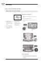
If pump 1, 2, 3, 4, 5 or the blower is not working:
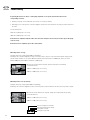
98
• Verifyifanerror
message is displayed on
the keypad. If so, refer
to the corresponding
section.
• Ensuretheselected
low-level configuration
is compatible with your
spa material.
If the indicator does not light up:
• Useareplacementkeypadtoverifythestateofthe
original.
• Replacethekeypadifdefective.
• Ifthekeypadworkscorrectly,replacethecontrol
system.
Pump 1, 2, 3, 4, 5 or the blower is not working
If the indicator lights up:
• Verifyyourpumpisworkingonbothspeeds(ifdual
speed pump) and your accessories works correctly
(ex: blower).
in.yj
in.ye and in.yt
in.xe
• Verifytheindicator
linked to your pump
and blower on the
keypad turns on when
you press on the
corresponding key.
Troubleshooting

13
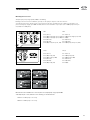
Pump 1 and
accessories fuse (F2)
Pump 1
high speed fuse (F1)
Pump 2 fuse (F3)Pump 1
low speed and
accessories fuse (F2)
Accesories fuse (F3)
If your pump is not working on both speeds (if dual
speed pump) or if your accessories (ex: blower) is not
working:
• Replacetheproblematicfuselinkedtoyourpumpor
your accessory (ex: blower) by a new one.
• Verifythefusereplacementrectifiestheproblem.
in.yj
in.ye et in.yt
in.xe
Pump 2 fuse
(F4)
Pump 3 and
accessories fuse (F21)
Pump 5 and
accessories fuse (F22)
Pump 4 and
accessories fuse (F23)
Pump 1 fuse (F1)Pump 2 fuse (F2)
Troubleshooting
Note: The accessories linked to every fuse are indicated as an example, every OEM has its own configurations.
Accesories fuse (F3)
in.xe-v2
Pump 1 fuse (F1)Pump 2 fuse (F2)

14
If replacing the fuse has no effect, or if the pump only works on one speed, measure the tension of the
corresponding connector:
• Activateyourpumpontheproblematicspeedortheaccessory(ex:blower).
• Referringtoyourcontrolsystemsconnexiondiagram,measurethetensionbetween:thepumporbloweroutputand
its return.
You should measure:
120 V for a 120 V pump or accessory
240 V for a 240 V pump or accessory
If the tension is compliant, verify the cables and connectors and replace if necessary. If need be, replace the pump
or the accessory.
If the tension is not compliant, replace the control system.
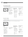
in.yj
in.ye and in.yt
Neutral
K7
Pin 3
Pin 1
Pin 1 (red / high speed output)
Pin 2 (black / low speed output)
Pin 3 (white / return)
Pin 4 (green / ground)
Measuring tension on in.yj:
Example: your pump 1 high speed (240V) is not working.
Referring to the connexion diagram you may see that the pump 1 output is connected on K7-P (Pump 1 high speed)
and the return should be on one of the TAB of line 2 (P14, P15, P16 or P37) for a 240V pump and on one of the
Neutral TAB (P18, P19, P20, P21 or P35) for a 120V pump.
Measure the tension between the K7-P and your return (Line 2 or Neutral),
you should measure:
120 V for a 120 V pump or accessory
240 V for a 240 V pump or accessory
Measuring tension on in.ye and in.yt:
Example: your pump 1 high speed (240V) is not working.
Referring to the connexion diagram you may see that the pump 1 output is linked to the A3 connector (pump 1 output).
Measure the tension between pin 1 (pump 1 high speed output) and pin 3 (return),
you should measure:
120 V for a 120 V pump or accessory
240 V for a 240 V pump or accessory
Troubleshooting

15
240 V 120 V
HC1
Pin 1 (Line 2)
Pin 2 (Output (1) high speed, 15A)
Pin 3 (Output (1) high speed, 20A)
Pin 4 (Ground)
Pin 5 (Neutral)
Pin 6 (Output (1) low speed, 15A)
Measuring tension on in.xe:
Example: your pump 1 high speed (240V) is not working.
Refering to the front connector identifiers, you may see the pump 1 output is on the P1 connector.
You may then refer to the “Connector pin out" on the front of the in.xe, you will notice the output for your pump 1 is on
pins 2 and 3 (pump 1 high speed 20A and 15A) and the return should be on pin 1 (line 2) for a 240V pump and on pin
5 (neutral) for a 120V pump.
Measure the tension between P1 connector pins 2-3 (output pump 1 high speed 20A
and 15A) and pin 1 or 5 (return line 2 or neutral), you should measure:
120 V for a 120 V pump or accessory
240 V for a 240 V pump or accessory
LC (1)
Pin 1 (Line 2)
Pin 2 (Output (3), 5A)
Pin 3 (Output (3-4), 10A)
Pin 4 (Ground)
Pin 5 (Neutral)
Pin 6 (Output (4), 5A)
LC (2)
Pin 1 (Line 2)
Pin 2 (Output (4), 5A)
Pin 3 (Output (4), 10A)
Pin 4 (Ground)
Pin 5 (Neutral)
Pin 6 (NC)
HC2
Pin 1 (Line 2)
Pin 2 (Output (2) high speed, 15A)
Pin 3 (NC)
Pin 4 (Ground)
Pin 5 (Neutral)
Pin 6 (Output (3) low speed, 15A)
P1
P1
P2P2
P5
P5
P3 P3
Troubleshooting
3
3
2 5
5 2
6
6
4
4
3
1
6
2
5
1
1
4

16
If the circulation pump is not working:
The circulation pump is not working
If the circulation pump is
not working :
• Ensuretheselected
low-level configuration
is compatible with your
spas material.
• Startthecirculation
pump, by setting the
consigned temperature
2 °F above the actual
water temperature.
98
If the mesured tension is
not compliant:
• Replacetheaccessories
fuse.
• Ifreplacingthefuse
does not fix the
problem, replace the
control system.
If the measured tension is
compliant:
• Replacethecirculation
pump.
Measure the tension
on the corresponding
connector:
• Referringtoyourcontrol
systems connexion
diagram, measure the
tension between: the
output of your circu-
lation pump and its
return.
You should measure:
120V for a 120V
circulation pump
240V for a 240 V
circulation pump
If the ozonator is not working:
The ozonator is not working
Note: The ozonator stops automatically when an accessory is started manually (pumps, blower, light).
If the ozonator is not
working:
• Verifiythestatusofthe
filtration cycle indicator
on the keypad display.
• Ifthe«Filtration»
indicator flashs, it is to
signal that the system
has interrupted the
filtration cycle. In that
case, restart the breaker
by cutting off then
restarting the power to
reinitialise the cycle.
98
If the mesured tension is
not compliant:
• Replacetheaccessories
fuse.
• Ifreplacingthefuse
does not fix the
problem, replace the
control system.
If the measured tension is
compliant:
• Replacetheozonator.
If the ozonator is not
working and the filtration
indicator is ON:
• Referringtothe
connexion digram of
your control system,
measure the tension
between : the ozonator
output and its return.
You should measure:
120V for a 120V
ozonator
240V for a 240V
ozonator
• Ifnot,startthefiltration
cycle (see your keypads
techbook for more
information).
Troubleshooting

17
Turn the system off and verify that all screws on the the terminal block are tight. Pull on the cables to ensure
that they are solidly fixed. Turn the device back on.
Nothing seems to be working (North American models)
For 240 V systems
• Ontheterminalblock,measurethetensionbetweenline1andline2.
You should measure 240V.
• Measurethetensionbetweenline1andneutral.Youshouldmeasure120V.
• Measurethetensionbetweenline2andneutral.Youshouldmeasure120V.
For 120V systems
• Measurethetensionbetweenline1andneutral.
You should measure 120 V.
L2
N
L1
G
L2
N
L1
G
L2
N
L1
G
L2
N
L1
G
in.yj
in.yj
in.ye & in.yt
in.ye & in.yt
in.xe
in.xe
Troubleshooting
Incorrect readings indicate an electrical cable problem. Call an electrician!
G
G
L2
L2
N
N
L1
L1

18
If readings are correct and keypad is linked correctly:
• Verifythetransformerfuse.(Availableonlyonin.ye,
in.yt and in.xe control systems).
• Replacethetransformerfuseifnecessary.
• Ifproblempersists,replacethecontrolsystem.
Troubleshooting
If readings are correct:
• Verifythatthekeypadislinkedcorrectlytothecontrol
system.
in.yj
in.ye and in.yt
in.xe
Transformer fuse
in.ye and in.yt
in.xe
Transformer fuse
in.xe-v2
Transformer fuse
Page is loading ...
Page is loading ...
Page is loading ...
Page is loading ...
Page is loading ...
Page is loading ...
Page is loading ...
Page is loading ...
-
 1
1
-
 2
2
-
 3
3
-
 4
4
-
 5
5
-
 6
6
-
 7
7
-
 8
8
-
 9
9
-
 10
10
-
 11
11
-
 12
12
-
 13
13
-
 14
14
-
 15
15
-
 16
16
-
 17
17
-
 18
18
-
 19
19
-
 20
20
-
 21
21
-
 22
22
-
 23
23
-
 24
24
-
 25
25
-
 26
26
-
 27
27
-
 28
28


Gecko in.yt Troubleshooting Manual
- Category
- Numeric keypads
- Type
- Troubleshooting Manual
Ask a question and I''ll find the answer in the document
Finding information in a document is now easier with AI
Related papers
Other documents
-
 Dynasty Spas SSPA-1 User manual
-
Intermatic P1121 User manual
-
Intermatic P1161 Owner's manual
-
 Aeware k-35 Series Quick Reference Card
-
 Aeware in.k400 User manual
-
-
 Beachcomber Hot Tubs ET-1000 Reference guide
-
 Aqua Flo Therma-Flo EHT User manual
-
Waterco Portapac Delta Hot User manual
-
 Endless Pools Swim Spa Operation and Maintenance Manual


