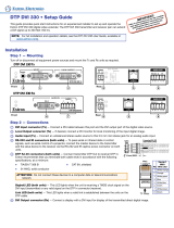
DTP2 R 211

Extron DTP2 R 211, DTP2 T 211 User manual

  • Hello! I am an AI chatbot trained to assist you with the Extron DTP2 R 211 User manual. I’ve already reviewed the document and can help you find the information you need or explain it in simple terms. Just ask your questions, and providing more details will help me assist you more effectively!
  • What are the maximum transmission distances for this device?
    What are the power requirements for this device?
    What is the purpose of the DTP RJ-45 ports?
    How do I connect the audio input for this device?
    How do I connect the HDMI input for this device?
    How do I connect the RS-232 and IR ports?
    How do I update the firmware for this device?
    Can I use this device to send remote power to another DTP device?
    What is the purpose of the LockIt lacing brackets?
    How do I know when the unit is receiving power?
1
IMPORTANT:
Go to www.extron.com for the complete
user guide, installation instructions, and
specifications before connecting the
product to the power source.
DTP2T/R 211 • Setup Guide
The DTP2 T 211 transmitters and DTP2 R 211 receivers can extend HDMI digital video signal with resolutions up to 4K@60Hz
(4:4:4), analog and digital embedded audio, bidirectional RS‑232 and IR control, and remote power up to 330feet (100meters),
using shielded twisted pair cabling as a transmission medium. This guide provides quick start instructions for an experienced
installer to set up and operate the DTP2211 digital video extenders.
NOTE: Maximum transmission distances will vary with resolutions used, cable types, and environment (see the
DTP2T/R 211UserGuide at www.extron.com for full specifications).
L
RS-323 IR
Tx Rx Tx RxG
R
POWER
12V
--A MAX
AUDIO
OUTPUTS
OVER DTP2
SIG LINK
DTP2 IN
POWER
12V
--A MAX
AUDIO
INPUTS
SIG LINK
DTP2 OUT
OVER DTP2
RS-232
IR
Tx Rx Tx RxG
POWER
12V
0.3A MAX
IPL PRO S3
G
Tx Rx RTS CTS
G
Tx Rx RTS CTS
G
Tx Rx RTS CTS
COM 1 COM 2 COM 3
LAN / PoE
INPUT
OFF
SEND
POWER
STATUS
OUTPUT
LINK
DTP2 T 211
CONFIG
INPUT
OFF
SEND
POWER
STATUS
OUTPUT
LINK
DTP2 R 211
CONFIG
RS-232
RS-232
HDMI
HDMIAudio
CATx Cable up to 330' (100 m)
4K HDR DisplayPC with 4K HDR Video Output
Extron
DTP2 T 211
Transmitter
Extron
IPL Pro S3
IP Link Pro
Control Processor
Extron
DTP2 R 211
Receiver
Figure 1. Typical Transmitter and Receiver Application
Installation
Turn off and disconnect all equipment power sources and mount the transmitter and receiver units as required. The transmitter
and receiver can be securely mounted in a variety of locations, using optional Extron Mounting Brackets and accessories (see the
Extron website, to determine which optional mounting accessories are compatible).
Rear Panel Connections
INPUTS
POWER
12V
0.8A MAX
SIG LINK
DTP2 OUT
OVER DTP2
RS-232
IR
Tx Rx Tx RxG
AUDIO
OUTPUTS
POWER
12V
0.8A MAX
SIG LINK
DTP2 IN
RS-232
IR
Tx Rx Tx RxG
LR
AUDIO
OVER DTP2
DTP2 T 211 Rear Panel DTP2 R 211 Rear Panel
E D
AA B
B C
C DD A
A E
E H
HDDEE GGFF
Figure 2. Rear Panels of the DTP2 T 211 and DTP2 R 211
A
Power inlet — Connect an IEC power cord between the included 12VDC, 1.5 A power supply and a 100‑240VAC, 50‑60Hz
source. Connect the power supply to either unit to power both units (see figure 3 on the next page to wire the power).
ATTENTION:
Do not connect any external power supplies until you have read the Attention notications in the Power Supply
section of the DTP2 T/R 211 User Guide.
Ne branchez pas de sources d’alimentation externes avant d’avoir lu les mises en garde dans la section « Power
Supply » du DTP2 T/R 211 User Guide.
figure 1
figure 2
2
DTP2T/R 211 • Setup Guide (Continued)
NOTE: One power supply is included with the transmitter and normally can power both units, if they are both from the
Extron DTP2 series.
SECTION A–A
Ridges
Smooth
A
A
3/16"
(5 mm) Max.
POWER
12V
--A MAX
Figure 3. Power Wiring Diagram
B
Audio input (Tx) — Connect an unbalanced stereo audio source (see image on the right) to this
3.5mm mini stereo port (see figure 2 on the previous page) for an analog audio input.
C
HDMI Input (Tx) — Connect an HDMI cable between this port and the HDMI output port of the digital video source.
NOTE: See the LockIt™ Lacing Brackets on the next page to securely fasten the HDMI connectors.
D
DTP RJ‑45 ports — Connect transmitter DTP2 Out to receiver DTP2 In, using a Twisted
Pair Cable. Extron recommends terminating both cable ends in accordance with the wiring
specifications in the diagram on the right, at a minimum:
TIA/EIA T 568 B CAT 6A, shielded 24 AWG, solid conductor
ATTENTION:
Do not connect these devices to a telecommunications or computer data network.
Ne connectez pas ces appareils à un réseau de télécommunications ou de données
informatiques.
E
RS‑232 and IR ports — To pass serial, infrared data, or control signals, connect the master device to the transmitter and the
slave device to the receiver via the RS‑232 and IRcaptive screw connectors on both units (see figure 4 for wiring).
Connected RS-232
and IR Device Pins
RS‑232
IR
Tx Rx Tx RxG
Tx/Rx
Pins
Ground
Receive pin
Transmit pin
Receive pin
Transmit pin
Figure 4. RS‑232 Wiring Diagram
F
HDMI Output (Rx) — Connect a display with an HDMI input to display the transmitted digital image.
G
Audio Configuration Switch (Rx) — Set the Toggle switch to the UP position to de‑embed digital audio from the HDMI
signal and output it to the captive screw connector for analog audio output. Set the Toggle switch to the DOWN position for
the analog input from the TRS audio connector on the Tx unit to be transported simultaneously with the digital embedded
HDMI audio and output on the captive screw connector.
H
Audio Output (Rx) — Connect a balanced or unbalanced audio device, such as an audio amplifier or powered speakers, to
the receiver via the audio captive screw connector (see figure 5 to wire analog audio output).
Do not tin
the wires!
Balanced Audio Output
Tip
Ring
Tip
Ring
Slee
ves
Unbalanced Audio Output
Tip
No Ground Here
No Ground Here
Tip
Sleeves
LR
LR
Figure 5. Balanced and Unbalanced Audio Output Wiring Diagram
ATTENTION:
For unbalanced audio, connect the sleeves to the ground contact. DO NOT connect the sleeves to the negative (–)
contacts.
Pour l’audio asymétrique, connectez les manchons au contact au sol. Ne PAS connecter les manchons aux
contacts négatifs (–).
NOTE: If the ground jumpers have been removed because of ground potential differences, the DTP2 T 211 transmitter
and DTP2 R 211 receiver cannot extend analog audio. No analog audio is output (see the DTP2T/R 211UserGuide at
www.extron.com for more information).
figure 3
figure 4
figure 5
Wire color
White-green
Green
White-orange
White-blue
Orange
White-brown
Brown
Blue
TIA/EIA T
568 B
TP Wires
12345678
Pins:
5
Pin
1
2
3
6
7
8
4
Sleeve ( )
Ring (
-
)
Tip (+)
3.5 mm Stereo Plug Connector
(unbalanced)
3
LockIt™ Lacing Brackets
Use an included LockIt lacing bracket to securely fasten an HDMI cable to each device as
follows:
1
Plug the HDMI cable into the panel connection.
2
Loosen the HDMI connection mounting screw from the panel enough to allow the
LockIt lacing bracket to be placed over it. The screw does not have to be removed.
3
Place the LockIt lacing bracket on the screw and against the HDMI connector, then
tighten the screw to secure the bracket.
ATTENTION:
Do not overtighten the HDMI connector mounting screw. The shield it
fastens to is very thin and can easily be stripped.
Ne serrez pas trop la vis de montage du connecteur HDMI. Le blindage
auquel elle est attachée est très n et peut facilement être dénudé.
4
Loosely place the included tie wrap around the HDMI connector and the LockIt lacing
bracket as shown.
5
While holding the connector securely against the lacing bracket, use pliers to tighten
the tie wrap, then remove any excess length.
3
11
2
2
3
3
4
4
5
5
Front Panel Features
DTP2 R 211
CONFIG
INPUT
LINK
OUTPUT
SEND
POWER
OFF
STATUS
DTP2 T 211
CONFIG
INPUT
LINK
OUTPUT
SEND
POWER
OFF
STATUS
DTP2 T 211 Front Panel DTP2 R 211 Front Panel
AA BB CC DD AA BB CC DD
Figure 6. Front Panels of the DTP2 T 211 and DTP2 R 211
A
Power LED — Lights when the unit is receiving power, either locally or remotely (on the DTP cable).
B
Configuration port — Using a USB cable, connect a PC to the transmitter or receiver via this front panel USB mini‑B port for
firmware updates.
C
Status LEDs
Input Signal LED — Lights when the unit is receiving a TMDS clock signal on the HDMI input (transmitter), or any valid
signal on the DTP2 In connector (receiver).
Link Status LED — Lights when a transmitter or receiver detect a signal from a connected DTP device.
Output Signal LED — Lights when the transmitter or receiver establish communication with the connected DTP device.
NOTE: The front panel LEDs are tied to the rear panel LEDs on the DTP connector (see figure 2,
D
on page1).
D
SEND POWER toggle switch — In a DTP2 transmitter to DTP2 receiver configuration, set the toggle switch to the UP
(SEND POWER) position on the powered DTP2 device to enable sending remote power to a DTP2 device on the far end. Set
the toggle switch to the DOWN (OFF) position on the DTP2 device receiving power (see figure 7 on the next page for toggle
switch configuration).
ATTENTION:
The DTP2 211 device is congured to output power to DTP2 models only. If connected to a Legacy DTP device, set
the toggle switch to the DOWN (OFF) position. Failure to turn the power OFF will damage the connected Legacy
DTP device.
Le DTP2 211 est conguré pour fournir une alimentation aux modèles DTP2 uniquement. S’il est connecté à un
autre appareil, veuillez positionner l’interrupteur à bascule sur « DOWN » (OFF). Si l’interrupteur n’est pas positionné
sur OFF, vous risquez d’entraîner la défaillance de l’appareil Legacy DTP connecté.
NOTE: DTP2 transmitters and receivers are compatible with Legacy DTP products. However, Remote Power must be
configured properly. Failure to do so will result in damage to the units (see figure 7 below).
figure 6
4
68-2938-50 Rev. A
05 19
For information on safety guidelines, regulatory compliances, EMI/EMF compatibility, accessibility, and related topics, see the
Extron Safety and Regulatory Compliance Guide on the Extron website.
© 2019 Extron Electronics — All rights reserved. www.extron.com
All trademarks mentioned are the property of their respective owners.
Worldwide Headquarters: Extron USA West, 1025 E. Ball Road, Anaheim, CA 92805, 800.633.9876
DTP2 R 211
CONFIG
INPUT
LINK
OUTPUT
SEND
POWER
OFF
STATUS
DTP2 T 211
CONFIG
INPUT
LINK
OUTPUT
SEND
POWER
OFF
STATUS
SEND
POWER
OFF
SEND
POWER
OFF
DTP2 R 211
CONFIG
INPUT
LINK
OUTPUT
SEND
POWER
OFF
STATUS
DTP2 T 211
CONFIG
INPUT
LINK
OUTPUT
SEND
POWER
OFF
STATUS
SEND
POWER
OFF
SEND
POWER
OFF
DTP2 R 211
CONFIG
INPUT
LINK
OUTPUT
SEND
POWER
OFF
STATUS
SEND
POWER
OFF
OFF
DTP2 T 211
CONFIG
INPUT
LINK
OUTPUT
SEND
POWER
OFF
STATUS
SEND
POWER
OFF
DTP HDMI 330 Rx
OVER DTP
RS-232
IR
Tx Rx Tx RxG
DTP HDMI 330 Tx
OFF
OFF ON
ON OFF
CATx Cable
up to 330' (100 m)
No Remote Power
Local
Power Supply
Local
Power Supply
Local
Power Supply
CATx Cable
up to 330' (100 m)
Local
Power Supply
Extron
DTP HDMI 4K 330 Tx
Transmitter
Extron
DTP2 R 211
Receiver
No Remote Power
Extron
DTP2 T 211
Transmitter
Extron
DTP HDMI 4K 330 Rx
Receiver
DTP Endpoint Connected to a DTP2 Endpoint
CATx Cable
up to 330' (100 m)
Direction of
Remote Power
Local
Power Supply
Extron
DTP2 T 211
Transmitter
Extron
DTP2 R 211
Receiver
CATx Cable
up to 330' (100 m)
Direction of
Remote Power
Extron
DTP2 T 211
Transmitter
Extron
DTP2 R 211
Receiver
DTP2 Endpoint Connected to a DTP2 Endpoint
Local
Power Supply
DTP2 R 211
CONFIG
INPUT
LINK
OUTPUT
SEND
POWER
OFF
STATUS
DTP2 T 211
CONFIG
INPUT
LINK
OUTPUT
SEND
POWER
OFF
STATUS
SEND
POWER
OFF
SEND
POWER
OFF
DTP2 R 211
CONFIG
INPUT
LINK
OUTPUT
SEND
POWER
OFF
STATUS
DTP2 T 211
CONFIG
INPUT
LINK
OUTPUT
SEND
POWER
OFF
STATUS
SEND
POWER
OFF
SEND
POWER
OFF
DTP2 R 211
CONFIG
INPUT
LINK
OUTPUT
SEND
POWER
OFF
STATUS
SEND
POWER
OFF
OFF
DTP2 T 211
CONFIG
INPUT
LINK
OUTPUT
SEND
POWER
OFF
STATUS
SEND
POWER
OFF
DTP HDMI 330 Rx
OVER DTP
RS-232
IR
Tx Rx Tx RxG
DTP HDMI 330 Tx
OFF
OFF ON
ON OFF
CATx Cable
up to 330' (100 m)
No Remote Power
Local
Power Supply
Local
Power Supply
Local
Power Supply
CATx Cable
up to 330' (100 m)
Local
Power Supply
Extron
DTP HDMI 4K 330 Tx
Transmitter
Extron
DTP2 R 211
Receiver
No Remote Power
Extron
DTP2 T 211
Transmitter
Extron
DTP HDMI 4K 330 Rx
Receiver
DTP Endpoint Connected to a DTP2 Endpoint
CATx Cable
up to 330' (100 m)
Direction of
Remote Power
Local
Power Supply
Extron
DTP2 T 211
Transmitter
Extron
DTP2 R 211
Receiver
CATx Cable
up to 330' (100 m)
Direction of
Remote Power
Extron
DTP2 T 211
Transmitter
Extron
DTP2 R 211
Receiver
DTP2 Endpoint Connected to a DTP2 Endpoint
Local
Power Supply
Figure 7. Send Power Toggle Switch Configuration
figure 7
/