Page is loading ...

FormNo.3392-628RevB
T42404-WheelDrive5-Plex
MowerTractionUnit
ModelNo.02750—SerialNo.315000001andUp
Registeratwww.Toro.com.
OriginalInstructions(EN)
*3392-628*B

ThisproductcomplieswithallrelevantEuropean
directives;fordetails,pleaseseetheseparateproduct
specicDeclarationofConformity(DOC)sheet.
Introduction
Thismachineisaride-on,reel-bladelawnmower
intendedtobeusedbyprofessional,hiredoperators
incommercialapplications.Itisprimarilydesigned
forcuttinggrassonwell-maintainedturf.Usingthis
productforpurposesotherthanitsintendedusecould
provedangeroustoyouandbystanders.
Readthisinformationcarefullytolearnhowtooperate
andmaintainyourproductproperlyandtoavoid
injuryandproductdamage.Youareresponsiblefor
operatingtheproductproperlyandsafely.
Visitwww.T oro.comformoreinformation,including
safetytips,trainingmaterials,accessoryinformation,
helpndingadealer,ortoregisteryourproduct.
Wheneveryouneedservice,genuineT oroparts,or
additionalinformation,contactanAuthorizedService
DealerorT oroCustomerServiceandhavethemodel
andserialnumbersofyourproductready.Themodel
andserialnumbersareonaplatemountedonthe
leftsideoftheframeunderthefootrest.Writethe
numbersinthespaceprovided.
ModelNo.
SerialNo.
Thismanualidentiespotentialhazardsandhas
safetymessagesidentiedbythesafetyalertsymbol
(Figure1),whichsignalsahazardthatmaycause
seriousinjuryordeathifyoudonotfollowthe
recommendedprecautions.
g000502
Figure1
Safety-alertsymbol
Thismanualuses2wordstohighlightinformation.
Importantcallsattentiontospecialmechanical
informationandNoteemphasizesgeneralinformation
worthyofspecialattention.
©2018—TheToro®Company
8111LyndaleAvenueSouth
Bloomington,MN55420
2
Contactusatwww.Toro.com.
PrintedintheUK
AllRightsReserved

Contents
Safety.......................................................................4
GeneralSafety...................................................4
SafetyandInstructionalDecals..........................4
ProductOverview.....................................................9
Controls...........................................................10
BrakingSystem..............................................11
WarningSystems..........................................15
IndicatorLights.............................................16
Specications..................................................17
Attachments/Accessories.................................17
BeforeOperation.................................................17
BeforeOperationSafety...................................17
PerformingDailyMaintenance..........................18
FillingtheFuelTank..........................................18
DuringOperation.................................................18
DuringOperationSafety...................................18
UsingtheOperatorPlatformLatching
Mechanism...................................................20
UnderstandingtheOperatorPresence
Controls........................................................20
StartingtheEngine...........................................21
ShuttingOfftheEngine.....................................21
FoldingtheRollBar..........................................21
CheckingtheInterlockSwitches.......................22
AdjustingtheHeightofCut...............................23
ControllingthePositionofanIndividual
CuttingUnit...................................................23
DualLiftCongurationControl..........................24
EngagingtheCuttingUnitDrive........................24
UsingtheWeight-Transfer/Traction
Assistance....................................................25
ClearingDebrisfromtheCuttingUnits..............25
OperatingTips.................................................25
AfterOperation....................................................26
AfterOperationSafety......................................26
IdentifyingtheTie-DownPoints........................27
HaulingtheMachine.........................................27
JackingPoints..................................................27
TowingtheMachine..........................................27
RecommissioningtheMachineafter
Towing...........................................................28
Maintenance...........................................................29
MaintenanceSafety..........................................29
RecommendedMaintenanceSchedule(s)...........29
DailyMaintenanceChecklist.............................31
Lubrication..........................................................32
GreasingtheBearings,Bushings,and
Pivots............................................................32
EngineMaintenance...........................................33
EngineSafety...................................................33
CheckingtheEngineOverheatWarning
System..........................................................33
ServicingtheAirCleaner..................................33
CheckingtheEngine-OilLevel..........................34
ChangingtheEngineOilandFilter....................34
FuelSystemMaintenance...................................35
DrainingtheFuelT ank......................................35
CheckingtheFuelLinesand
Connections..................................................35
ReplacingtheFuelFilterCanister.....................35
BleedingtheFuelSystem.................................36
BleedingAirfromtheFuelInjectors...................36
ElectricalSystemMaintenance...........................37
ElectricalSystemSafety...................................37
ServicingtheBattery.........................................37
DriveSystemMaintenance..................................38
CheckingtheTirePressure...............................38
CheckingtheT orqueoftheWheel
Nuts..............................................................38
ChangingtheTransmission-OilFilter................38
CheckingtheRearWheelAlignment.................38
CoolingSystemMaintenance..............................39
CoolingSystemSafety.....................................39
CheckingtheCoolingSystem...........................39
RemovingDebrisfromtheCooling
System..........................................................40
BeltMaintenance................................................40
CheckingtheConditionandTensionofthe
AlternatorBelt...............................................40
HydraulicSystemMaintenance...........................41
HydraulicSystemSafety...................................41
CheckingtheHydraulicLinesand
Hoses............................................................41
ServicingtheHydraulicSystem........................41
HydraulicFluidCapacity...................................41
CheckingtheHydraulicFluid............................41
ChangingtheHydraulicOilReturn
Filter..............................................................43
CheckingtheHydraulicOilOverheat
WarningSystem............................................43
CuttingUnitMaintenance.....................................44
BladeSafety.....................................................44
Cleaning..............................................................44
WashingtheMachine.......................................44
Storage...................................................................45
StorageSafety..................................................45
PreparingtheTractionUnit...............................45
PreparingtheEngine........................................45
Troubleshooting......................................................46
3

Safety
Thismachinehasbeendesignedinaccordancewith
ENISO5395.
GeneralSafety
Thisproductiscapableofamputatinghandsandfeet
andofthrowingobjects.
•Readandunderstandthecontentsofthis
Operator’sManualbeforestartingtheengine.
•Useyourfullattentionwhileoperatingthe
machine.Donotengageinanyactivitythat
causesdistractions;otherwise,injuryorproperty
damagemayoccur.
•Donotputyourhandsorfeetnearmoving
componentsofthemachine.
•Donotoperatethemachinewithoutallguards
andothersafetyprotectivedevicesinplaceand
functioningproperlyonthemachine.
•Keepchildren,bystanders,andpetsoutofthe
operatingarea.Neverallowchildrentooperate
themachine.
•Shutofftheengine,removethekey,waitforall
movementtostopbeforeyouleavetheoperator’s
position.Allowthemachinetocoolbefore
adjusting,servicing,cleaning,orstoringit.
Improperlyusingormaintainingthismachinecan
resultininjury.Toreducethepotentialforinjury,
complywiththesesafetyinstructionsandalways
payattentiontothesafety-alertsymbol
,which
meansCaution,Warning,orDanger—personalsafety
instruction.Failuretocomplywiththeseinstructions
mayresultinpersonalinjuryordeath.
SafetyandInstructionalDecals
Safetydecalsandinstructionsareeasilyvisibletotheoperatorandarelocatednearanyarea
ofpotentialdanger.Replaceanydecalthatisdamagedormissing.
decal70-13-072
70-13-072
1.Jackingpoint
decal70-13-077
70-13-077
1.Warning—stoptheengineandremovetheignitionkey
beforereleasingoroperatingsafetylatches.
decal70-13-078
70–13–078
1.Dieselfuel
4

decal924868
924868
1.Tippinghazard—donotoperatethemachineunlessthe
platformiscorrectlyseatedandthelatchislockedinplace.
decal950832
950832
1.Tirepressure
decal950889
950889
1.Warning—hotsurfaces.
decal953829
953829
1.Crushinghazard,cuttingunit—alwayslowerthecutting
unitsbeforegoingnearthem.
decal953876
953876
1.Differentiallock
4.Reversespeed
2.Pushdowntoengagethe
differentiallock.
5.Forwardspeed
3.Pulluptodisengagethe
differentiallock.
5
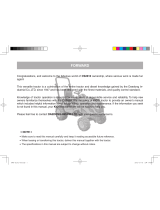
decal953877
953877
1.Forwardspeed
3.Slow
2.Fast
decal994912
994912
1.Engagetheparkingbrake.
7.Raise/lowertheright
cuttingunit.
2.Disengagetheparking
brake.
8.Horn
3.Fast9.Ignitionswitch
4.Slow
10.Engagethereel.
5.Raise/lowertheleftcutting
unit.
11.Disengagethereel.
6.Raise/lowerthecenter
cuttingunit.
12.Engagebacklapping.
decal111-0773
111-0773
1.Warning—crushingofngers,forceappliedfromside.
6

decal111-3901
111-3901
1.Transmissionuid—readtheOperator'sManual.
decal111-3902
111-3902
1.Yourhandcanbecutbythefan;warning
2.Hotsurfaces;readtheOperator'sManual.
decal953812
953812
1.Fuellevel,diesel5.Aircleaner
9.Seatswitch13.Coolantlevel—30to40mm
(1to1.5inches)
2.Engineoil
6.Cutterheads
10.Hoselines
14.Greasepoints
3.Tirepressure
7.Cleanandinspectthe
machine.
11.Hydraulicuid
4.Fasteners
8.Wheelnuttorque—front,
200N∙m(147ft-lb);rear,54
N∙m(40ft-lb)
12.Radiator/screens
7

decal111-8098
111-8098
Note:Thismachinecomplieswiththeindustrystandardstabilitytestinthestaticlateralandlongitudinaltestswiththemaximum
recommendedslopeindicatedonthedecal.ReviewtheinstructionsforoperatingthemachineonslopesintheOperator’sManualas
wellastheconditionsinwhichyouwouldoperatethemachinetodeterminewhetheryoucanoperatethemachineintheconditions
onthatdayandatthatsite.Changesintheterraincanresultinachangeinslopeoperationforthemachine.Ifpossible,keepthe
cuttingunitsloweredtothegroundwhileoperatingthemachineonslopes.Raisingthecuttingunitswhileoperatingonslopescan
causethemachinetobecomeunstable.
1.Tippinghazard—driveslowlywhenturningorgoingupslopes.
4.Warning—readtheOperator'sManual;removethekeyfrom
theignitionbeforeservicingorperformingmaintenance.
2.Tippinghazard—onlydriveupslopesthatarebetween0and
18°;donotdriveupslopesthataregreaterthan18°.
5.Thrownobjecthazard—keepbystandersaway.
3.Tippinghazard—wearaseatbeltwhentherollbarisup;donot
wearaseatbeltwhentherollbarisdown.
8
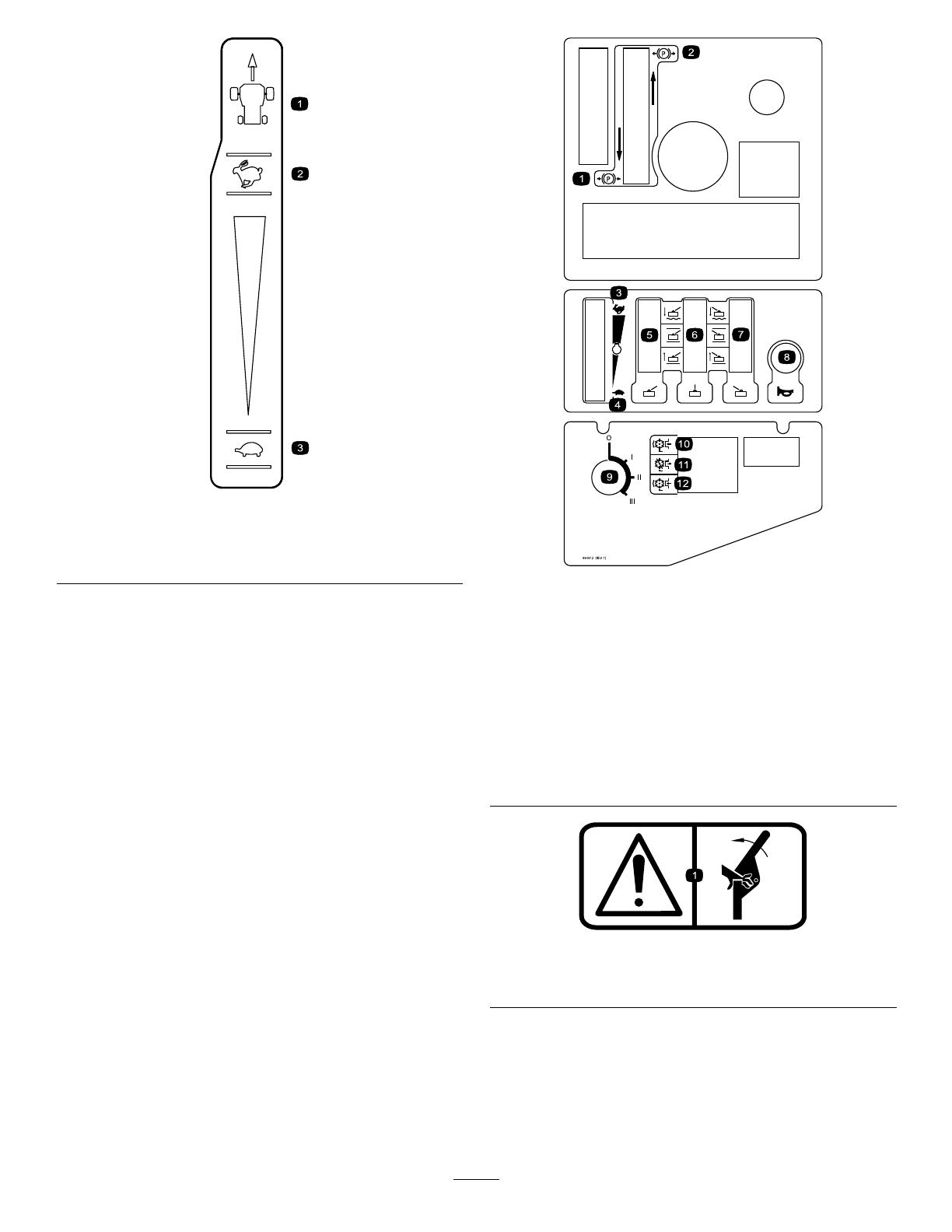
ProductOverview
g029192
Figure2
1.Frontcuttingunits4.Enginehood
2.Steeringwheel
5.Rearcuttingunit
3.Operator'sseat
9
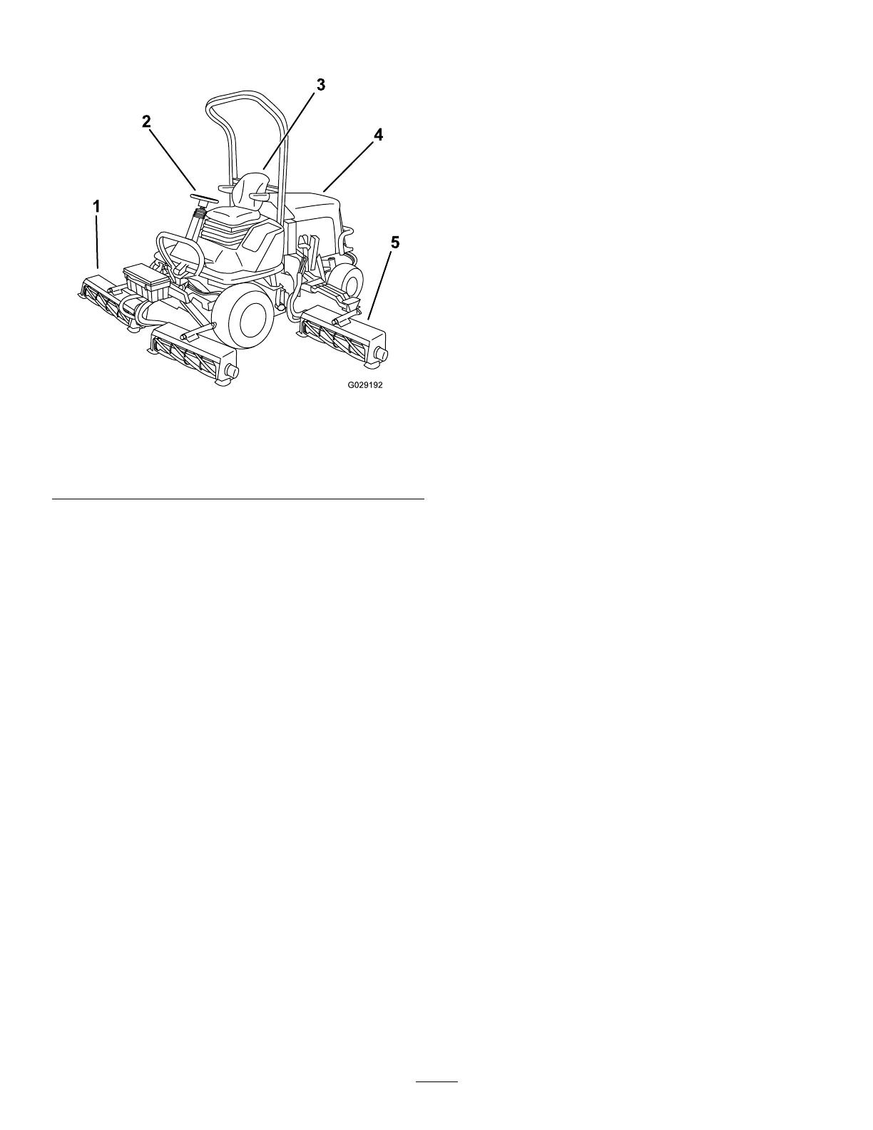
Controls
ControlPanelComponents
g029346
Figure3
1.Throttle-controllever
7.Lightingswitch(supplied
withlightingkit)
13.Hourmeter
19.Transmission-oillter
indicator
2.Cutting-unit-positionlever
8.Warning-beaconswitch
(suppliedwithbeaconkit)
14.Transmission-neutral
indicator
20.Hornbutton
3.Parking-brakelever9.Hazard-warningswitch
(suppliedwithlightingkit)
15.Parking-brakeindicator21.Direction-indicatorswitch
(suppliedwithlightingkit)
4.Work/Transportmode
switch
10.Engine
temperature-warning
indicator
16.Cutting-unitdrive-off
indicator
22.Dipbeam/mainbeam
lightswitch(suppliedwith
lightingkit)
5.Weight-transfercontrol
11.Transmission-temperature
indicator
17.Glow-plugindicator23.Cutting-unitdriveswitch
6.Duallift-conguration
switch
12.Oil-pressureindicator
18.Battery-warningindicator24.Ignitionkey
10
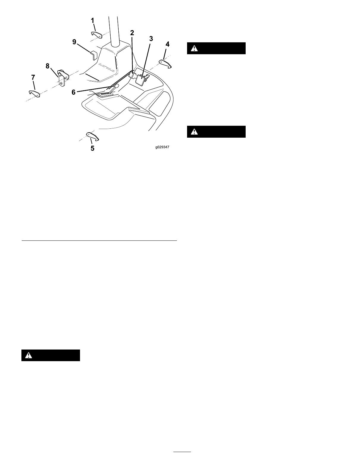
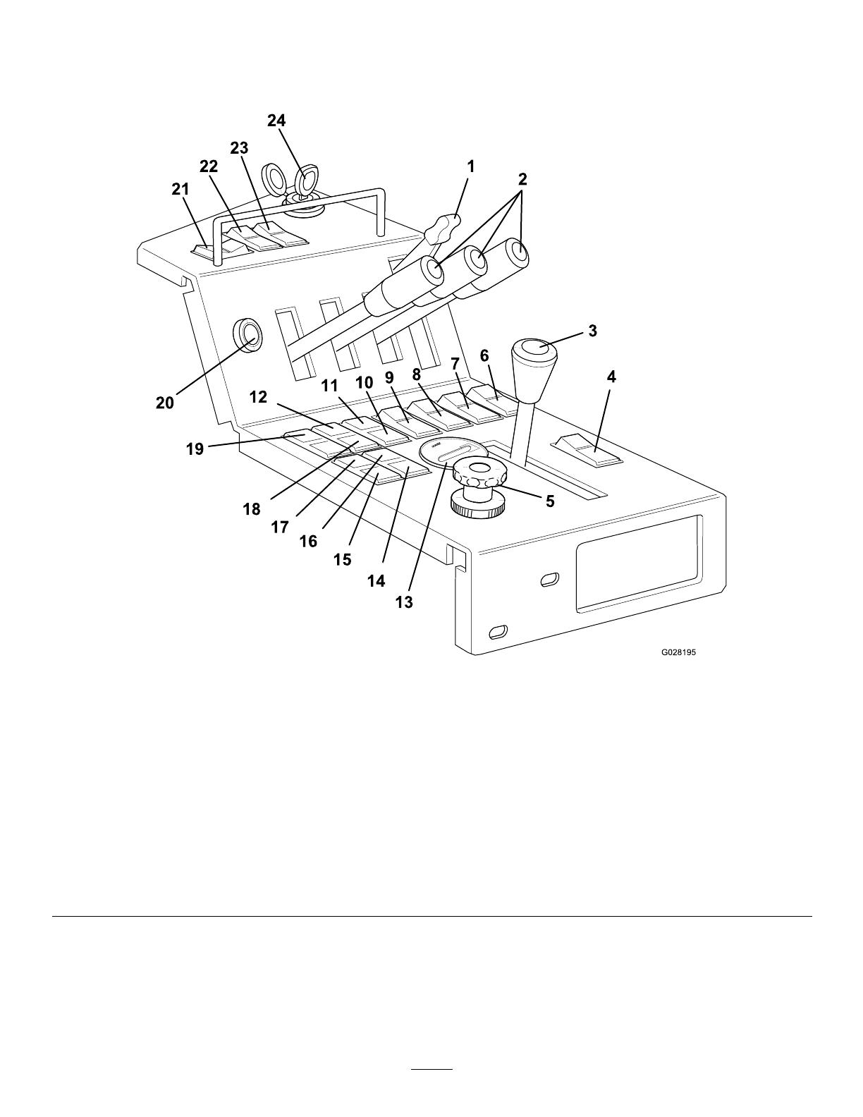
g029347
Figure4
1.Left,frontcutting-unit
transportlatch
6.Forwardtravelspeed
backstoplever
2.Reverse-travelpedal
7.Leftwing-unittransport
latch
3.Forward-travelpedal
8.Centercutting-unit
transportlatch
4.Right,frontcutting-unit
transportlatch
9.Differentiallockpedal
5.Rightwing-unittransport
latch
BrakingSystem
ParkingBrake
Movetheparkingbrakeswitchtotherearwardposition
bypressingthesmallerlockingbuttonandmovingthe
switchforwardtoengagetheparkingbrake(Figure3).
Note:Donotoperatethemachinewiththeparking
brakeengagedanddonotengagetheparkingbrake
whilethemachineismoving.
Thislightilluminateswhentheparkingbrakeis
engagedandtheignitionkeyisturnedtopositionI.
WARNING
Theparkingbrakeoperatesonthefront
wheelsonly.Donotparkthemachineona
slope.
ServiceBrake
Servicebrakingisachievedbythehydraulic
transmissionsystem.Whentheforwardorreverse
travelpedalsarereleasedortheenginespeed
reduced,servicebrakingbecomeseffectiveandtravel
speedisautomaticallyreduced.T oincreasethe
brakingeffect,pushthetransmissionpedalintothe
neutralposition.Servicebrakingiseffectiveonthe
frontwheelsonly.
WARNING
Theservicebrakingsystemisnotabletohold
themoweratastandstill.Alwaysensurethe
parkingbrakeisengagedtoparkthemower
atastandstill.
EmergencyBrake
Intheeventofservicebrakefailure,turntheignition
offtobringthemowertoastandstill.
WARNING
Takecarewhenusingtheemergencybraking.
Remainseatedandholdontothesteering
wheeltopreventejectionfromthemower
causedbythefrontwheelbrakesbeing
appliedsuddenlywhentraveling.
ThrottleControl
Operatethethrottlecontrolinaforwarddirection
toincreasetheenginespeed.Operatethethrottle
controlinarearwarddirectiontoreduceenginespeed
(Figure3).
Note:Theenginespeeddictatesthespeedofthe
otherfunctions,i.e.travel,cuttingcylinderrotation
speedandcuttingunitliftspeed.
TravelPedals
Forwardtravel:Presstheforwardtravelpedalto
increaseforwardtravelspeed.Releasethepedalto
reducespeed(Figure4).
Reversetravel:Pressthereversetravelpedalto
increasereversetravelspeed.Releasethepedalto
reducespeed(Figure4).
Stop(Neutral):Releasetheforwardorreversetravel
pedal.
Work/TransportMode
SelectWORKmodewhenoperatingthemachinein
poortractionconditionswhenyouneedmaximum
tractiveperformance(Figure3).SelectingWORK
modewillenabletheuseofthedifferentiallock.
SelectTRANSPORTmodewhenoperatingthemachine
ingoodtractioncondition(i.e.,whentravelingon
publichighwayormowinglarge,level,openareas).
SelectingTRANSPORTmodeintheseconditionswill
reducetransmissionsystemwearandtear.
11

Note:Thedifferentiallockisnotavailableforuse
whentheTRANSPORTmodeisselected.
TransportLatches
Alwaysraisethecuttingunitstothetransportposition
andsecurewiththetransportlatchesandsafetylocks
whentravelingbetweenworkareas(Figure5).
g014548
Figure5
DifferentialLock
WARNING
Donotengagethedifferentiallockathigh
speed.Theturningcirclewillincreasewith
thedifferentiallockengaged.
Engagethedifferentiallocktoincreasetractiveeffort.
Onlyengagethedifferentiallockatslowspeeds
(Figure4).Itwilloperatewhilethemachineismoving
forwardandreverse.
Toengagethedifferentiallock,pressthedifferential
lockpedal.T odisengagethedifferentiallock,release
thedifferentiallockpedal.
Note:Thedifferentiallockiseffectiveonlywhen
WORKisselected.
ForwardTravelSpeedBackstop
Lever
Usethebackstoplevertolimitthemovementofthe
forwardpedalforaccurateforwardtravelspeedand
tolimittheclipraterequired(Figure4).
Movetheleverforwardtoincreasethetravelspeed
settingandrearwardtodecreaseit.
Note:Thisisnotacruise-controldevice.Releasing
theforwardtravelpedalwillallowittoreturntoneutral.
CuttingUnitDriveSwitch
AlwaysputthecuttingunitdriveswitchintheOFF
positionwhentravelingbetweenworkareas.
AdjustableSteeringColumn
WARNING
Neveroperatethemachinewithoutrst
checkingthatthesteeringcolumnadjuster
mechanismisingoodworkingorderandthat,
onceadjustedandlocked,thesteeringwheel
remainssecurelyinposition.
Onlyadjustthesteeringwheelandsteeringcolumn
whenthemachineisatastandstillwiththeparking
brakeengaged.
Toadjusttheangleofthesteeringwheel,movethe
leverdown,adjusttheangle,andreleasethelever
(Figure6).
Toadjusttheheightofthesteeringcolumn,move
theleverup,adjusttheheight,andreleasethelever
(Figure6).
g029196
Figure6
1.Adjusttheangleofthe
steeringwheel.
3.Lever
2.Adjusttheheightofthe
steeringcolumn.
12
OperatorSeat
WARNING
Neveroperatethemachinewithoutrst
checkingthattheoperatorseatmechanisms
areingoodworkingorderandthat,once
adjustedandlocked,theseatremains
securelyinposition.
Onlyadjusttheseatmechanismswhenthe
machineisatastandstillwiththeparking
brakeengaged.
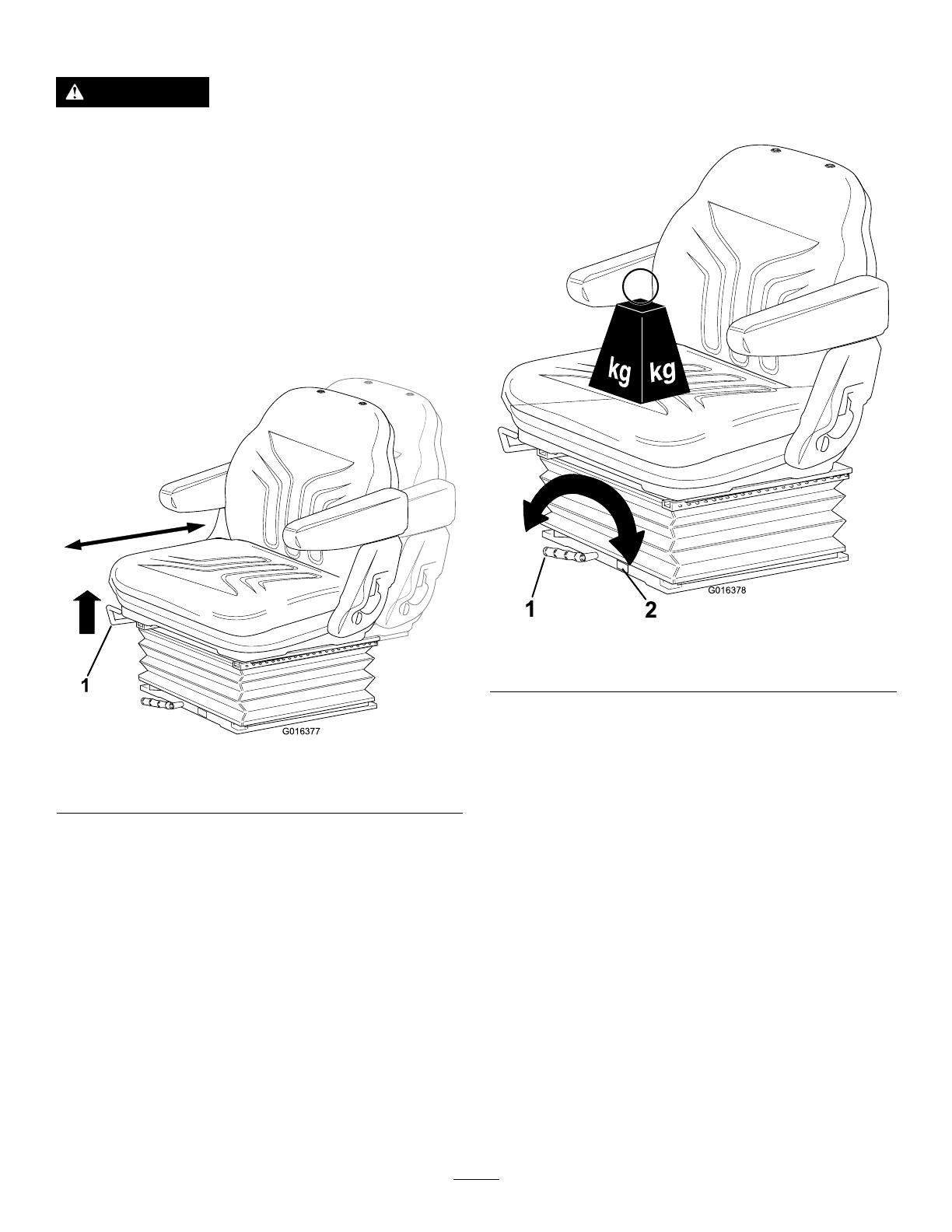
•Fore/AftAdjustment:Movetheleverupwardto
adjustthefore/aftpositionoftheseat.Releasethe
levertolocktheseatinposition(Figure7).
g016377
Figure7
1.Lever
•Operatorweightadjustment:Rotatethehandle
clockwisetoincreasesuspensionstiffnessand
counter-clockwisetodecrease.Thedialindicates
whentheoptimumsuspensionadjustmenthas
beensetaccordingtooperatorweight(Figure8).
g016378
Figure8
1.Lever2.Dial
13
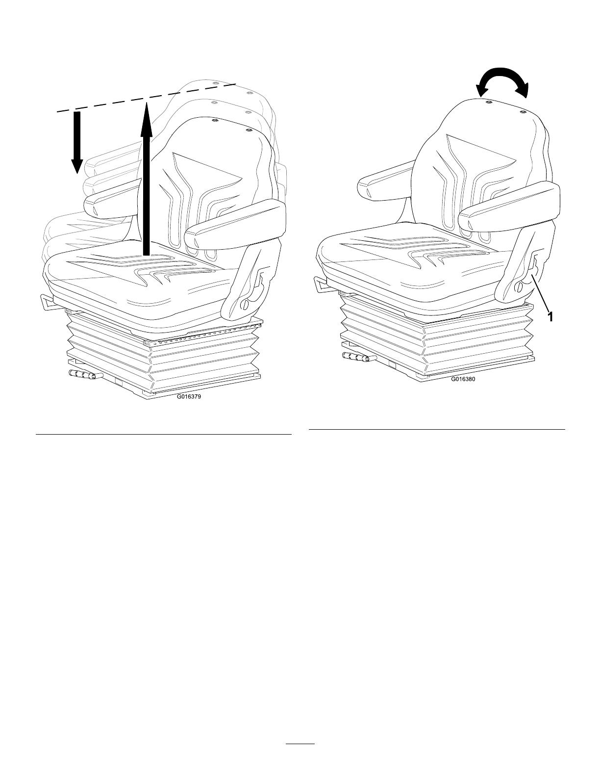
•Heightadjustment:Manuallylifttheseatfor
incrementalheightadjustment.Tolower,liftthe
seatbeyonditshighestsetting,thenallowitto
droptothelowestsetting(Figure9).
g016379
Figure9
•Backrestadjustment:Pullthehandleoutward
toadjusttheseatbackrestangle.Releasethe
handletolocktheseatbackrestinposition.
g016380
Figure10
1.Handle
14
WarningSystems
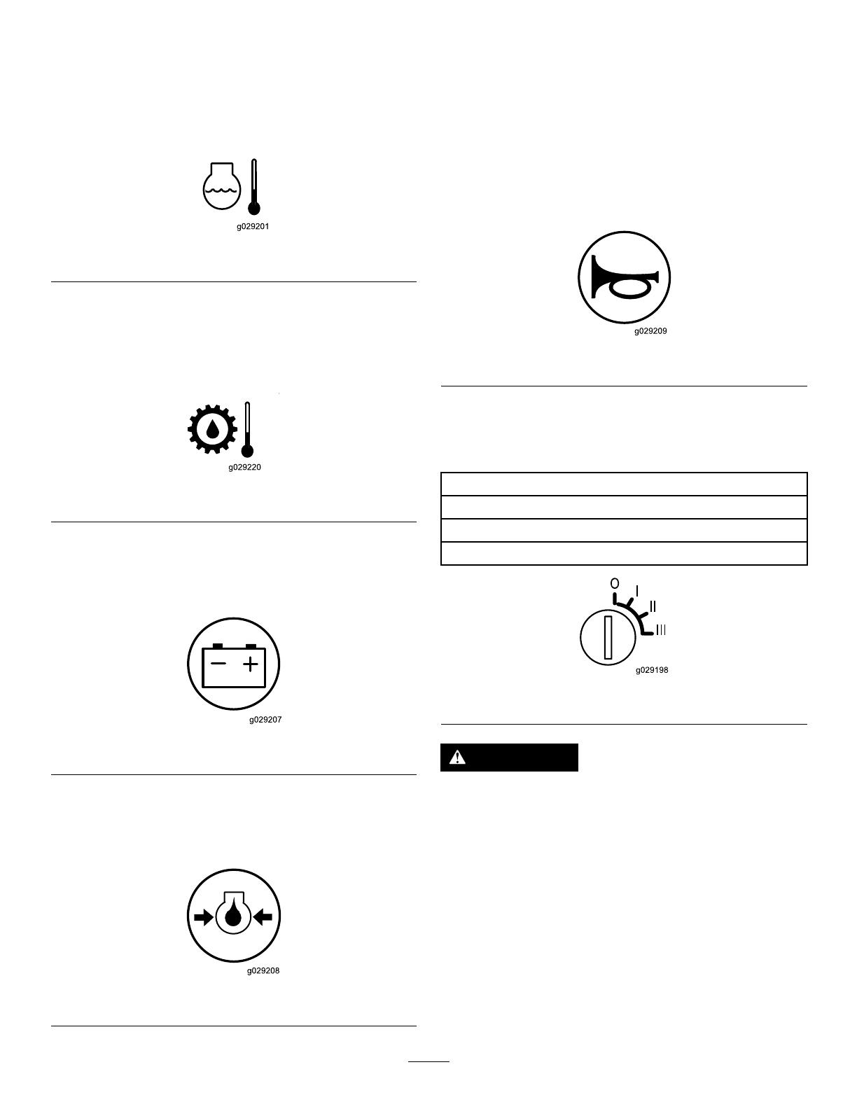
Engine-CoolantOverheatingWarning
Theengine-coolantwarninglight(Figure11)
illuminatesandthehornsoundsiftheenginecoolant
overheats.
g029201
Figure11
HydraulicOilOverheatingWarningLight
Thehydraulic-oilwarninglight(Figure12)illuminates
andthehornsoundswhenthehydraulicoilinthe
reservoirexceeds95°C(203°F).
g029220
Figure12
LowBatteryChargeWarningLight
Thebattery-chargewarninglight(Figure13)
illuminateswhenthebatterychargeislow.
g029207
Figure13
LowEngine-OilPressureWarningLight
Theengine-oilpressurewarninglight(Figure14)
illuminateswhentheoilpressureistoolow.
g029208
Figure14
AudibleWarningHorn
ServiceInterval:Beforeeachuseordaily—Check
thehorn.
PresstheHORNbutton(Figure15)toprovidean
audiblewarning.
Important:Thehornautomaticallysoundswhen
anenginecoolantorhydraulicuidoverheat
conditionoccurs.Shutofftheengineimmediately
andxthemachinebeforestarting.
g029209
Figure15
IgnitionKey
Theignitionkeypositionsareasfollows:
0=Engineoff
I=Enginerun/auxiliaryon
II=Enginepre-heat
III=Enginestart
g029198
Figure16
WARNING
Alwaysremovetheignitionkeywhenthe
machineisnotinuse.
Important:Alwaysinstalltheprotectivecapwhen
theignitionkeyisremovedtopreventingressof
dirtandmoisturedamagingthemechanism.
15

FuelGauge
Thefuelgaugeshowstheamountoffuelinthetank
(Figure17).
g014558
Figure17
HourMeter
Thehourmetershowsthetotalhoursthatthemachine
hasbeenoperated(Figure3).
IndicatorLights
EnginePre-HeatIndicatorLight
TurntheignitionkeytopositionII.Theenginepreheat
indicatorlightwillilluminate(Figure18)andheatthe
glowplugs.
Important:Attemptingtostartacoldengine
beforeusingthepre-heatcancauseunnecessary
weartothebattery.
g029199
Figure18
Transmission-Neutral-IndicatorLight
Thetransmission-neutral-indicatorlight(Figure19)
illuminateswhenthetravelcontrolpedalisinthe
NEUTRALpositionandtheignitionkeyisturnedto
positionI.
Note:Theparkingbrakemustbeengagedforthe
transmissionneutralindicatorlighttoilluminate.
g029211
Figure19
Cutting-Unit-Drive-SwitchIndicatorLight
Thecutting-unit-drive-switchindicatorlight(Figure20)
illuminateswhenthecuttingunitdriveswitchisinthe
OFFpositionandtheignitionkeyisturnedtopositionI.
g029212
Figure20
Parking-Brake-IndicatorLight
Theparking-brake-indicatorlight(Figure21)
illuminateswhentheparkingbrakeisengagedand
theignitionkeyisturnedtopositionI.
g029251
Figure21
Hydraulic-Transmission-Filter-IndicatorLight
Thehydraulic-transmission-lter-indicatorlight(Figure
22)illuminateswhenthetransmissionlterelement
isblocked.
Note:Theenginemustberunningfortheindicator
lighttoilluminate.Theindicatorlightmayilluminate
brieywhenthehydraulicoiliscold.
g029370
Figure22
16

Specications
Note:Specicationsanddesignaresubjecttochangewithoutnotice.
Specication
Model02750
TransportWidth
1890mm(74.5inches)
Widthofcut3460mm(136.2inches)
Length
2930mm(115.0inches)
Height
1775mm(70.0inches)withROPSfolded
2385mm(94.0inches)withROPSintheverticaloperatingposition
Weight(with2-postROPS,8-inch/6-blade
cuttingunits,anduids)
1870kg(4123lb)
Engine
Kubota35.3kw(47.3hp)@2800rpmDIN70020V2203diesel4cylindersinline
Fueltankcapacity
70L(18.5USgallons)
Travelspeed
0to24km/h(0to15mph)
Recommendedmaximummowingspeed
11km/h(6.85mph)
Hydraulicsystemcapacity
77L(20.3USgallons)
Attachments/Accessories
AselectionofToroapprovedattachmentsand
accessoriesisavailableforusewiththemachine
toenhanceandexpanditscapabilities.Contact
yourAuthorizedServiceDealerorauthorizedToro
distributororgotowww.Toro.comforalistofall
approvedattachmentsandaccessories.
Toensureoptimumperformanceandcontinuedsafety
certicationofthemachine,useonlygenuineT oro
replacementpartsandaccessories.Replacement
partsandaccessoriesmadebyothermanufacturers
couldbedangerous,andsuchusecouldvoidthe
productwarranty.
Operation
BeforeOperation
BeforeOperationSafety
GeneralSafety
•Neverallowchildrenoruntrainedpeopleto
operateorservicethemachine.Localregulations
mayrestricttheageoftheoperator.Theowner
isresponsiblefortrainingalloperatorsand
mechanics.
•Becomefamiliarwiththesafeoperationofthe
equipment,operatorcontrols,andsafetysigns.
•Shutofftheengine,removethekey(ifequipped),
andwaitforallmovementtostopbeforeyouleave
theoperator’sposition.Allowthemachinetocool
beforeadjusting,servicing,cleaning,orstoringit.
•Knowhowtostopthemachineandshutoffthe
enginequickly.
•Donotoperatethemachinewithoutallguards
andothersafetyprotectivedevicesinplaceand
functioningproperlyonthemachine.
17

•Beforemowing,alwaysinspectthemachineto
ensurethatthecuttingunitsareingoodworking
condition.
•Inspecttheareawhereyouwillusethemachine
andremoveallobjectsthatthemachinecould
throw.
FuelSafety
•Useextremecareinhandlingfuel.Itisammable
anditsvaporsareexplosive.
•Extinguishallcigarettes,cigars,pipes,andother
sourcesofignition.
•Useonlyanapprovedfuelcontainer.
•Donotremovethefuelcaporllthefueltank
whiletheengineisrunningorhot.
•Donotaddordrainfuelinanenclosedspace.
•Donotstorethemachineorfuelcontainerwhere
thereisanopename,spark,orpilotlight,such
asonawaterheaterorotherappliance.
•Ifyouspillfuel,donotattempttostarttheengine;
avoidcreatinganysourceofignitionuntilthefuel
vaporshavedissipated.
PerformingDaily
Maintenance
ServiceInterval:Beforeeachuseordaily
Beforestartingthemachineeachday,performthe
EachUse/DailyprocedureslistedinMaintenance
(page29).
FillingtheFuelTank
FuelTankCapacity
70L(18.5USgallons)
FuelSpecication
Failuretoobservethefollowingcautionsmaydamage
theengine.
•Neverusekeroseneorgasolineinsteadofdiesel
fuel.
•Nevermixkeroseneorusedengineoilwiththe
dieselfuel.
•Neverkeepfuelincontainerswithzincplatingon
theinside.
•Donotusefueladditives.
PetroleumDiesel
Useonlyclean,freshdieselfuelorbiodieselfuelswith
low(<500ppm)orultra-low(<15ppm)sulfurcontent.
Theminimumcetaneratingshouldbe40.Purchase
fuelinquantitiesthatcanbeusedwithin180days
toensurefuelfreshness.
Usesummer-gradedieselfuel(Number2-D)at
temperaturesabove-7°C(20°F)andwinter-grade
dieselfuel(Number1-DorNumber1-D/2-Dblend)
below-7°C(20°F).Usingwinter-gradefuelatlower
temperaturesprovidesalowerashpointand
cold-owcharacteristics,whichwilleasestartingand
reducefuel-lterplugging.
Usingsummer-gradefuelabove-7°C(20°F)will
contributetowardlongerfuel-pumplifeandincreased
powercomparedtowinter-gradefuel.
AddingFuel
1.Parkthemachineonalevelsurface.
2.Usingacleanrag,cleanareaaroundthe
fuel-tankcap.
3.Removethecapfromthefueltank.
4.Fillthetankuntilthelevelistothebottomofthe
llerneckwithdieselfuel.
5.Installfuel-tankcaptightlyafterllingtank.
Note:Ifpossible,llthefueltankaftereach
use.Thiswillminimizepossiblebuildupof
condensationinsidethefueltank.
DuringOperation
DuringOperationSafety
GeneralSafety
•Theowner/operatorcanpreventandisresponsible
foraccidentsthatmaycausepersonalinjuryor
propertydamage.
•Wearappropriateclothing,includingeye
protection;longtrousers;substantial,slip-resistant
footwear;andhearingprotection.Tiebacklong
hairanddonotwearlooseclothingorloose
jewelry.
•Donotoperatethemachinewhileill,tired,or
undertheinuenceofalcoholordrugs.
•Useyourfullattentionwhileoperatingthe
machine.Donotengageinanyactivitythat
causesdistractions;otherwise,injuryorproperty
damagemayoccur.
•Beforeyoustarttheengine,ensurethatalldrives
areinneutral,theparkingbrakeisengaged,and
youareintheoperatingposition.
•Donotcarrypassengersonthemachineandkeep
bystandersandchildrenoutoftheoperatingarea.
18

•Operatethemachineonlyingoodvisibilitytoavoid
holesorhiddenhazards.
•Avoidmowingonwetgrass.Reducedtraction
couldcausethemachinetoslide.
•Keepyourhandsandfeetawayfromthecutting
units.
•Lookbehindanddownbeforebackinguptobe
sureofaclearpath.
•Usecarewhenapproachingblindcorners,shrubs,
trees,orotherobjectsthatmayobscureyour
vision.
•Stopthecuttingunitswheneveryouarenot
mowing.
•Slowdownandusecautionwhenmakingturns
andcrossingroadsandsidewalkswiththe
machine.Alwaysyieldtheright-of-way.
•Operatetheengineonlyinwell-ventilatedareas.
Exhaustgasescontaincarbonmonoxide,which
islethalifinhaled.
•Donotleavearunningmachineunattended.
•Beforeyouleavetheoperator’sposition,dothe
following:
–Parkthemachineonalevelsurface.
–Disengagethecuttingunit(s)andlowerthe
attachments.
–Engagetheparkingbrake.
–Shutofftheengineandremovethekey(if
equipped).
–Waitforallmovementtostop.
•Operatethemachineonlyingoodvisibilityand
appropriateweatherconditions.Donotoperate
themachinewhenthereistheriskoflightning.
RolloverProtectionSystem
(ROPS)Safety
•DonotremovetheROPSfromthemachine.
•Ensurethattheseatbeltisattachedandthatyou
canreleaseitquicklyinanemergency.
•Checkcarefullyforoverheadobstructionsanddo
notcontactthem.
•KeeptheROPSinsafeoperatingconditionby
thoroughlyinspectingitperiodicallyfordamage
andkeepingallthemountingfastenerstight.
•ReplaceadamagedROPS.Donotrepairoralter
it.
MachineswithaFoldableRollBar
•Alwaysusetheseatbeltwiththerollbarinthe
raisedposition.
•TheROPSisanintegralsafetydevice.Keepa
foldingrollbarintheraisedandlockedposition,
andusetheseatbeltwhenoperatingthemachine
withtherollbarintheraisedposition.
•Lowerafoldingrollbartemporarilyonlywhen
necessary.Donotweartheseatbeltwhenthe
rollbarisfoldeddown.
•Beawarethatthereisnorolloverprotectionwhen
afoldedrollbarisinthedownposition.
•Checktheareathatyouwillbemowingandnever
folddownafoldingrollbarinareaswherethere
areslopes,drop-offs,orwater.
SlopeSafety
•Slopesareamajorfactorrelatedtolossofcontrol
androlloveraccidents,whichcanresultinsevere
injuryordeath.Theoperatorisresponsiblefor
safeslopeoperation.Operatingthemachineon
anysloperequiresextracaution.
•Evaluatethesiteconditionstodetermineifthe
slopeissafeformachineoperation,including
surveyingthesite.Alwaysusecommonsense
andgoodjudgmentwhenperformingthissurvey.
•Reviewtheslopeinstructionslistedbelowfor
operatingthemachineonslopesandreviewthe
conditionsinwhichyouwilloperatethemachine
todeterminewhetheryoucanoperateitinthe
conditionsonthatdayandatthatsite.Changes
intheterraincanresultinachangeinslope
operationforthemachine.
•Avoidstarting,stopping,orturningthemachineon
slopes.Avoidmakingsuddenchangesinspeedor
direction.Maketurnsslowlyandgradually.
•Donotoperateamachineunderanyconditions
wheretraction,steering,orstabilityisinquestion.
•Removeormarkobstructionssuchasditches,
holes,ruts,bumps,rocks,orotherhiddenhazards.
Tallgrasscanhideobstructions.Uneventerrain
couldoverturnthemachine.
•Beawarethatoperatingthemachineonwet
grass,acrossslopes,ordownhillmaycausethe
machinetolosetraction.Lossoftractiontothe
drivewheelsmayresultinslidingandalossof
brakingandsteering.
•Useextremecautionwhenoperatingthemachine
neardropoffs,ditches,embankments,water
hazardsorotherhazards.Themachinecould
suddenlyrolloverifawheelgoesovertheedge
ortheedgecavesin.Establishasafetyarea
betweenthemachineandanyhazard.
•Identifyhazardsatthebaseoftheslope.
Iftherearehazards,mowtheslopewitha
pedestrian-controlledmachine.
•Ifpossible,keepthecuttingunit(s)loweredtothe
groundwhileoperatingonslopes.Raisingthe
19
cuttingunit(s)whileoperatingonslopescancause
themachinetobecomeunstable.
•Useextremecautionwithgrasscollectionsystems
orotherattachments.Thesecanchangethe
stabilityofthemachineandcausealossofcontrol.
UsingtheOperatorPlatform
LatchingMechanism
WARNING
Neveroperatethemachinewithoutrst
checkingthattheoperatorplatformlatching
mechanismisfullyengagedandingood
workingorder.
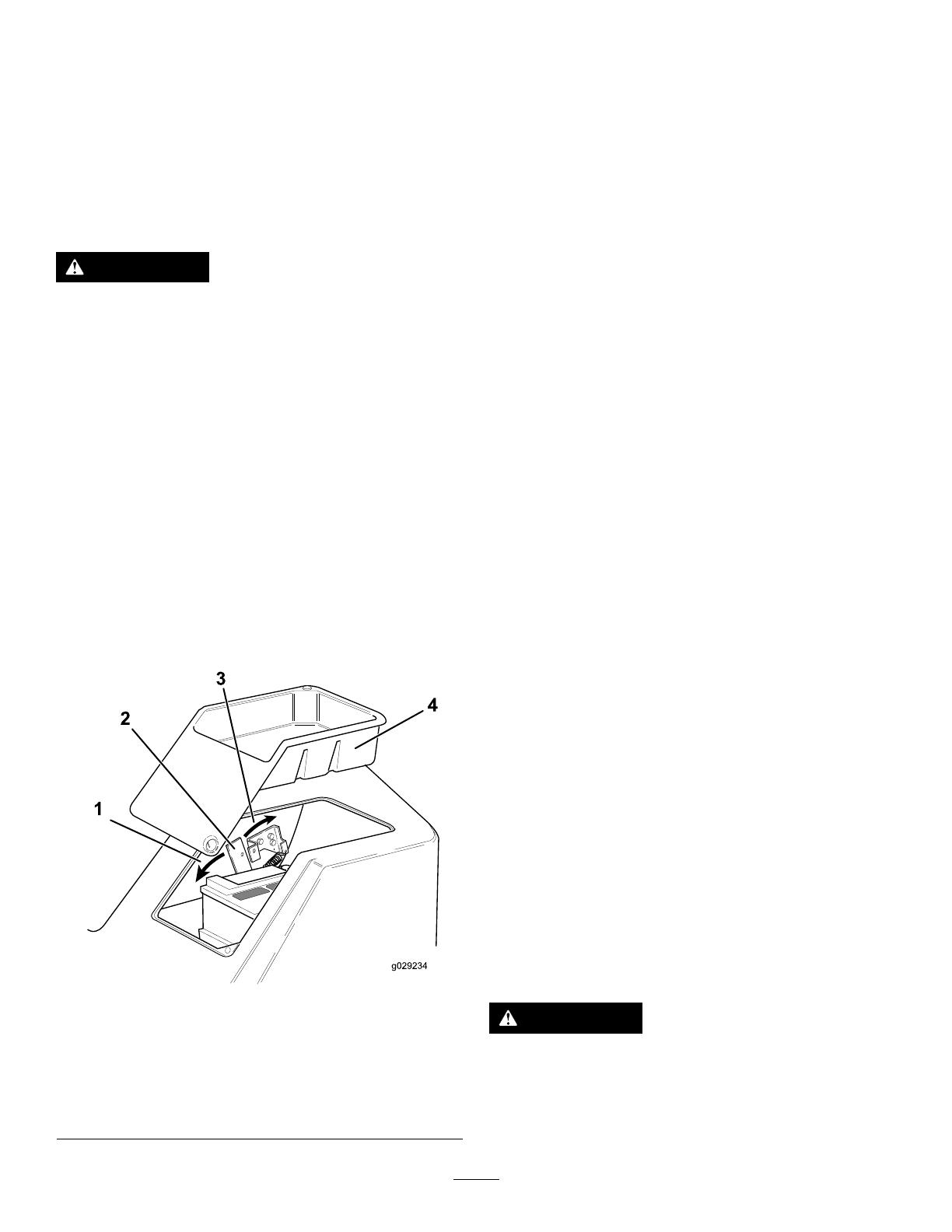
ReleasingthePlatform
1.Ensurethatthefront2cuttingunitsarelowered
totheground.
2.Releaseandremovethetooltrayfromtheleft
sideoftheplatform(Figure23).
3.Releasethepadlocksecuringthelockinglatch
handlewiththekeyprovided.
4.Movethelockinglatchhandletowardthefront
ofthemachineuntilthelatchhooksclearthe
lockingbarandraisetheplatform(Figure23).
Note:Thegasspringwillprovideassistance.
g029234
Figure23
1.Towardfrontofthe
machine
3.Towardrearofmachine
2.Lockinglatchhandle4.Tooltray
SecuringthePlatform
1.Lowertheplatformcarefully.
Note:Thegasspringwillprovideassistance.
2.Movethelockinglatchhandletowardthefront
ofthemachineastheplatformnearsthefully
loweredposition(Figure23).
Note:Thiswillensurethatthelatchhooksclear
thelockingbar.
3.Fullylowertheplatformandmovethelocking
latchhandletowardtherearofthemachineuntil
thelatchhooksfullyengagethelockingbar
(Figure23).
4.Installthepadlocktosecurethelockinglatch
handleinplace.
Understandingthe
OperatorPresence
Controls
Note:Theenginestopsiftheoperatorleavesthe
seatwithoutengagingtheparkingbrake.
EngineStartLockout:Theenginecanonlybe
startedwhentheforward/reversetravelpedalisinthe
NEUTRALposition,thecuttingunitdriveswitchisin
theOFFpositionandtheparkingbrakeisengaged.
Whenthesecircumstancesaresatised,switchesare
activated,permittingtheenginetobestarted.
EngineRunInterlock:Afterstartingtheengine,you
mustbeseatedbeforereleasingtheparkingbrakefor
theenginetocontinuetorun.
CuttingCylinderDriveLockout:Thedrivetothe
cuttingcylindersisonlypossiblewhenyouareseated.
Ifyouraiseofftheseatforaperiodofmorethan1
second,aswitchactivatesandthedrivetothecutting
cylindersautomaticallydisengages.T oengagedrive
tothecuttingcylinders,returntotheseat,thenoperate
thecuttingunitdriveswitchtotheOFFpositionbefore
movingitbacktotheONposition.Ifyouriseoffthe
seatforabriefmomentduringnormalwork,driveto
thecuttingcylindersisnotaffected.
Theenginecanonlybestartedwiththecutting-unit
driveswitchintheOFFposition.
WARNING
Donotoperatetheturfmachineiftheoperator
presencecontrolsaremalfunctioninginany
way.Alwaysreplacedamagedorwornparts
andcheckthattheyfunctioncorrectlybefore
operatingthemachine.
20
/