Lantech IPGS-3208C User manual
- Category
- Network switches
- Type
- User manual
This manual is also suitable for

I(P)GS-3208GSFP
I(P)GS-3208C
I(P)GS-3204MGSFP
I(P)GS-3008
I(P)ES-3008
IP30-rated Series
IP30-rated OS2 Industrial Managed Ethernet Switch
User Manual (Hardware)
Oct. 2022

Recommendation for Shielded network cables
STP cables have additional shielding material that is used to reduce external interference.
The shield also reduces the emission at any point in the path of the cable. Our
recommendation is to deploy an STP network cable in demanding electrical environments.
Examples of demanding indoor environments are where the network cable is located in
parallel with electrical mains supply cables or where large inductive loads such as motors
or contactors are in close vicinity to the camera or its cable. It is also mandatory to use an
STP cable where the power device (like IP camera) is used outdoors or where the network
cable is routed outdoors.

Important Notice
Lantech Communications Global, Inc. reserves the right to modify the
equipment, its specification or this manual without prior notice, in the interest
of improving performance, reliability, or servicing. At the time of publication
all data is correct for the operation of the equipment at the voltage and/or
temperature referred to. Performance data indicates typical values related to
the particular product.
No part of this documentation or information supplied may be divulged to any
third party without the express written consent of Lantech Communications
Global Inc. Products offered may contain software which is proprietary to
Lantech Communications Global Inc. The offer or supply of these products
and services does not include or infer any transfer of ownership.
Interference Issues
This Equipment has been tested and found to comply with the limits for a
Class A digital device, pursuant to Part 15 of the FCC rules. These limits are
designed to provide reasonable protection against harmful interference in a
commercial or industrial installation. This equipment generates, uses, and
can radiate radio frequency energy. It may cause harmful interference to
radio communications if the equipment is not installed and used in
accordance with the instructions.

FCC Warning
This Equipment has been tested and found to comply with the limits for a
Class-A digital device, pursuant to Part 15 of the FCC rules. These limits
are designed to provide reasonable protection against harmful interference
in a residential installation. This equipment generates, uses, and can
radiate radio frequency energy. It may cause harmful interference to radio
communications if the equipment is not installed and used in accordance
with the instructions. However, there is no guarantee that interference will
not occur in a particular installation. If this equipment does cause harmful
interference to radio or television reception, which can be determined by
turning the equipment off and on, the user is encouraged to try to correct
the interference by one or more of the following measures:
Reorient or relocate the receiving antenna.
Increase the separation between the equipment and receiver.
Connect the equipment into an outlet on a circuit different from that to
which the receiver is connected.
Consult the dealer or an experienced radio/TV technician for help.
CE Mark Warning
This is a Class-A product. In a domestic environment this product may
cause radio interference in which case the user may be required to take
adequate measures.

Content
Chapter 1 Model List .............................................. 1
Chapter 2 Hardware Description............................ 2
2.1 Physical Dimension & Front Panel ................ 3
2.2 Package Content: ........................................11
2.3 IP Protection ................................................11
2.4 LED Indicators .............................................14
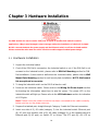
Chapter 3 Hardware Installation .......................... 16
3.1 Hardware installation....................................16
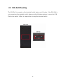
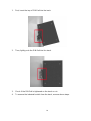
3.2 DIN-Rail Mounting ........................................18
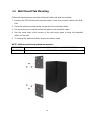
3.3 Wall Mount Plate Mounting ..........................20
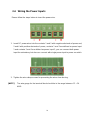
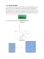
3.4 Wiring the Power Inputs ...............................21
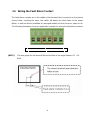
3.5 Wiring the Fault Alarm Contact ....................22
3.6 Wiring the DIDO ...........................................23
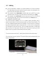
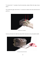
3.7 Cabling ........................................................24
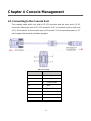
Chapter 4 Console Management.......................... 27
4.1. Connecting to the Console Port....................27
4.2. Login in the Console Interface ......................28

1
Chapter 1 Model List
Model Name
10/100/1000T
Port
10/100TX
Port
1G/2.5G
SFP Port
1G
SFP
Port
10/100/1000T/
100M/1000M
SFP Combo
Port
USB
Port
IPGS-
3208GSFP
8 with PoE
at/af
2
1
IGS-
3208GSFP
8
2
1
IPGS-3208C
8 with PoE
at/af
2
1
IGS-3208C
8
2
1
IPGS-
3204MGSFP
4 with PoE
at/af
2
1
IGS-
3204MGSFP
4
2
1
IPGS-3008
8 with 8 or 6
PoE at/af
IGS-3008
8
IPES-3008
8 with 8
or 6 PoE
at/af
IES-3008
8
IP30 rated
L2+ managed
Enhanced G.8032 Ring
*For detail specifications, please refer to product datasheet.
**The revise authority rights of product specifications belong to Lantech Communications
Global, Inc. Lantech may make changes to specification and product descriptions at
anytime, without notice.

2
Chapter 2 Hardware Description
In this paragraph, it will describe the Industrial switch’s hardware spec, port, cabling
information, and wiring installation.

3
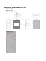
2.1 Physical Dimension & Front Panel
IPGS-3208GSFP
Metal case. IP-30,
74 (W) x 114 (D) x 152 (H) mm
Front Panel

4
IGS-3208GSFP
Metal case. IP-30,
74 (W) x 114 (D) x 152 (H) mm
Front Panel

5
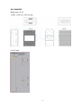
IPGS-3208C
Metal case. IP-30,
74 (W) x 114 (D) x 152 (H) mm
Front Panel

6
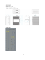
IGS-3208C
Metal case. IP-30,
74 (W) x 114 (D) x 152 (H) mm
Front Panel

7
IPGS-3204MGSFP
Metal case. IP-30,
43 (W) x 114 (D) x 152 (H) mm
Front Panel

8
IGS-3204MGSFP
Metal case. IP-30,
35 (W) x 114 (D) x 152 (H) mm
Front Panel

9
IPGS-3008 / IPES-3008
Metal case. IP-30,
43 (W) x 114 (D) x 152 (H) mm
Front Panel

10
IGS-3008 / IES-3008
Metal case. IP-30,
35 (W) x 114 (D) x 152 (H) mm
Front Panel

11
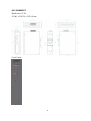
2.2 Package Content:
Manual CD (by request)
Product
Console cable
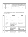
2.3 IP Protection
The IP Code, Ingress Protection Rating, sometimes also interpreted as International
Protection Rating, classifies and rates the degree of protection provided against the
intrusion (including body parts such as hands and fingers), dust, accidental contact, and
water in mechanical casings and with electrical enclosures. It is published by the
International Electrotechnical Commission (IEC)
Solid particle protection
The first digit indicates the level of protection that the enclosure provides against access
to hazardous parts (e.g., electrical conductors, moving parts) and the ingress of solid
foreign objects.
Level
Object size
protected against
Effective against
0
—
No protection against contact and ingress of objects
1
>50 mm
Any large surface of the body, such as the back of a
hand, but no protection against deliberate contact
with a body part
2
>12.5 mm
Fingers or similar objects
3
>2.5 mm
Tools, thick wires, etc.
4
>1 mm
Most wires, screws, etc.

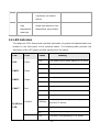
12
5
Dust protected
Ingress of dust is not entirely prevented, but it must
not enter in sufficient quantity to interfere with the
satisfactory operation of the equipment; complete
protection against contact
6
Dust tight
No ingress of dust; complete protection against
contact
Liquid ingress protection
The second digit indicates the level of protection that the enclosure provides against
harmful ingress of water.
Level
Protected
against
Testing for
Details
0
Not
protected
—
—
1
Dripping
water
Dripping water (vertically
falling drops) shall have no
harmful effect.
Test duration: 10 minutes
Water equivalent to 1 mm
rainfall per minute
2
Dripping
water when
tilted up to
15°
Vertically dripping water
shall have no harmful effect
when the enclosure is tilted
at an angle up to 15° from
its normal position.
Test duration: 10 minutes
Water equivalent to 3 mm
rainfall per minute
3
Spraying
water
Water falling as a spray at
any angle up to 60° from
the vertical shall have no
harmful effect.
Test duration: 5 minutes
Water volume: 0.7 litres per
minute
Pressure: 80–100 kPa
4
Splashing
of water
Water splashing against
the enclosure from any
direction shall have no
Test duration: 5 minutes
Water volume: 10 litres per
minute

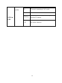
13
harmful effect.
Pressure: 80–100 kPa
5
Water jets
Water projected by a
nozzle (6.3 mm) against
enclosure from any
direction shall have no
harmful effects.
Test duration: at least
15 minutes
Water volume: 12.5 litres per
minute
Pressure: 30 kPa at distance
of 3 m
6
Powerful
water jets
Water projected in powerful
jets (12.5 mm nozzle)
against the enclosure from
any direction shall have no
harmful effects.
Test duration: at least
3 minutes
Water volume: 100 litres per
minute
Pressure: 100 kPa at
distance of 3 m
7
Immersion
up to 1 m
Ingress of water in harmful
quantity shall not be
possible when the
enclosure is immersed in
water under defined
conditions of pressure and
time (up to 1 m of
submersion).
Test duration: 30 minutes
Immersion at depth of at
least 1 m measured at
bottom of device, and at least
15 cm measured at top of
device
8
Immersion
beyond 1 m
The equipment is suitable
for continuous immersion in
water under conditions
which shall be specified by
the manufacturer.
Normally, this will mean
that the equipment is
hermetically sealed.
However, with certain types
of equipment, it can mean
that water can enter but
Test duration: continuous
immersion in water
Depth specified by
manufacturer

14
only in such a manner that
it produces no harmful
effects.
9
Powerful
high
temperature
water jets
Protected against close-
range high pressure, high
temperature spray downs.
—
2.4 LED Indicators
The diagnostic LEDs that provide real-time information of system and optional status are
located on the front panel of the industrial switch. The following table provides the
description of the LED status and their meanings for the switch.
LED
Color
Status
Meaning
R.M
Green
On
The switch unit is owner switch of ITU-Ring
Off
The switch is not owner switch
PWR1
Green
On
Power 1 is active
Off
Power 1 is inactive
PWR2
Green
On
Power 2 is active
Off
Power 2 is inactive
FAULT
Red
On
Power or port failure
Off
No failure
RJ45 Port
LED
Link/Ack
On
A network device is detected.
Blinking
The port is transmitting or receiving packets
from the TX device.
Off
No device attached
Speed 1000M
On
The port is operating in 1000T mode.
PoE FWD
Off
The port is not operating in PoE mode.

15
(For PoE
model)
On
The port is operating in PoE mode.
SFP Port
LED
On
A network device is detected.
Blinking
The port is transmitting or receiving packets
from the TX device.
Off
No device attached.
Page is loading ...
Page is loading ...
Page is loading ...
Page is loading ...
Page is loading ...
Page is loading ...
Page is loading ...
Page is loading ...
Page is loading ...
Page is loading ...
Page is loading ...
Page is loading ...
Page is loading ...
Page is loading ...
-
 1
1
-
 2
2
-
 3
3
-
 4
4
-
 5
5
-
 6
6
-
 7
7
-
 8
8
-
 9
9
-
 10
10
-
 11
11
-
 12
12
-
 13
13
-
 14
14
-
 15
15
-
 16
16
-
 17
17
-
 18
18
-
 19
19
-
 20
20
-
 21
21
-
 22
22
-
 23
23
-
 24
24
-
 25
25
-
 26
26
-
 27
27
-
 28
28
-
 29
29
-
 30
30
-
 31
31
-
 32
32
-
 33
33
-
 34
34


Lantech IPGS-3208C User manual
- Category
- Network switches
- Type
- User manual
- This manual is also suitable for
Ask a question and I''ll find the answer in the document
Finding information in a document is now easier with AI
Related papers
-
Lantech IES-3424DSFP-2P User manual
-
-
-
-
-
-
-
-
-
Other documents
-
Planet IGS-20160HPT Quick start guide
-
-
-
-
-
-
-
Moxa SDS-3008 Series Quick setup guide
-
-
Planet IGS-5225-8P2T2S User manual