Page is loading ...

Lantech
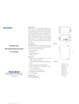
IPGS-0005T-4
4 10/100/1000T PoE at + 1 1000T Industrial Unmanaged Switch
User Manual
V1.03
Nov. 2022

Content
Overview ............................................................ 1
Introduction .............................................................. 1
Features / Model List ................................................ 2
Packing List .............................................................. 3
Safety Precaution ..................................................... 3
Hardware Description ......................................... 4
Dimensions .............................................................. 4
Wiring the Power Inputs ........................................... 6
Wiring the Fault Alarm Contact ................................ 7
LED Indicators .......................................................... 8
RJ-45 Pin Assignments .......................................... 10
Cabling ................................................................... 12
Mounting Installation ........................................ 13
DIN-Rail Mounting .................................................. 13
Wall-Mount Plate Mounting (Optional) ................... 15
Hardware Installation ....................................... 16
Installation Steps .................................................... 17


Recommendation for Shielded network
cables
STP cables have additional shielding material that is used to reduce external
interference. The shield also reduces the emission at any point in the path of the cable.
Our recommendation is to deploy an STP network cable in demanding electrical
environments. Examples of demanding indoor environments are where the network
cable is located in parallel with electrical mains supply cables or where large inductive
loads such as motors or contactors are in close vicinity to the camera or its cable. It is
also mandatory to use an STP cable where the power device (like IP camera) is used
outdoors or where the network cable is routed outdoors.

Important Notice
Lantech Communications Global, Inc. reserves the right to modify the
equipment, its specification or this manual without prior notice, in the
interest of improving performance, reliability, or servicing. At the time of
publication all data is correct for the operation of the equipment at the
voltage and/or temperature referred to. Performance data indicates typical
values related to the particular product.
No part of this documentation or information supplied may be divulged to
any third party without the express written consent of Lantech
Communications Global Inc. Products offered may contain software which
is proprietary to Lantech Communications Global Inc. The offer or supply of
these products and services does not include or infer any transfer of
ownership.
Interference Issues
This Equipment has been tested and found to comply with the limits for a
Class A digital device, pursuant to Part 15 of the FCC rules. These limits
are designed to provide reasonable protection against harmful interference
in a commercial or industrial installation. This equipment generates, uses,
and can radiate radio frequency energy. It may cause harmful interference
to radio communications if the equipment is not installed and used in
accordance with the instructions.

FCC Warning
This Equipment has been tested and found to comply with the limits for a
Class-A digital device, pursuant to Part 15 of the FCC rules. These limits
are designed to provide reasonable protection against harmful interference
in a residential installation. This equipment generates, uses, and can
radiate radio frequency energy. It may cause harmful interference to radio
communications if the equipment is not installed and used in accordance
with the instructions. However, there is no guarantee that interference will
not occur in a particular installation. If this equipment does cause harmful
interference to radio or television reception, which can be determined by
turning the equipment off and on, the user is encouraged to try to correct
the interference by one or more of the following measures:
Reorient or relocate the receiving antenna.
Increase the separation between the equipment and receiver.
Connect the equipment into an outlet on a circuit different from that to
which the receiver is connected.
Consult the dealer or an experienced radio/TV technician for help.
CE Mark Warning
This is a Class-A product. In a domestic environment this product may
cause radio interference in which case the user may be required to take
adequate measures.

1
Overview
Introduction
The unmanaged industrial switch is a cost-effective solution and meets
the high reliability requirements demanded by industrial applications.
High-Speed Transmissions
The Industrial switch includes a switch controller that can automatically
sense transmission speeds (10/100/1000 Mbps). The RJ-45 interface
can also be auto-detected, so MDI or MDI-X is automatically selected
and a crossover cable is not required. All Ethernet ports have memory
buffers that support the store-and-forward mechanism. This assures that
data is properly transmitted.
Dual Power Inputs
To reduce the risk of power failure, the Industrial switch provides dual
power inputs. When power failure occurs, the device will automatically
switch to the secondary power input.
Flexible Mounting
The industrial switch is extremely compact and can be mounted on a
DIN-rail or a panel, so it is suitable for any space-constrained
environment.
Wide Operating Temperature
The operating temperature of the Industrial switch is in the range
between -40 ~ 75oC. With such a wide range, you can use the Industrial
switch in some of the harshest industrial environments that exist.
Easy Troubleshooting
LED indicators make troubleshooting quick and easy. Each
10/100/1000T port has 2 LED indicators that display the link status,
transmission speed and collision status. Also other LED indicators help
you diagnose the system immediately.

2
Features / Model List
Store-and-Forward switching architecture
8K MAC address table
Supports full/half duplex flow control
IEEE 802.3at/af PoE+ standard (PoE models)
Supports MDI/MDI-X auto-crossover
Relay contact to connect with alarm system
Provides flexible mounting: DIN-rail, Panel Mounting*
Model Name
10/100/1000T
Power
Supply
Operating
Temperature
IPGS-0005T-4-12V
5 (PoE x4)
9.5~56VDC
-40 ~ 75℃
IPGS-0005T-4-48V
5 (PoE x4)
44~56VDC
-40 ~ 75℃
*Optional

3
Packing List
1 x Industrial Ethernet Switch (w/ terminal block and DIN-Rail kit)
Caps for RJ45-port
Safety Precaution
Attention
If DC voltage is supplied by an external circuit, please use a
protection device on the power supply input.

4
Hardware Description
In this paragraph, we will introduce the Industrial switch’s dimensions,
port, cabling information, and wiring installation.
For POE models: Do not use units' POE ports to uplink to another POE switch in
vehicle applications. (May Cause Damage) Lantech strongly advise the installation
of a Galvanic isolated DC/DC converter between the power supply and the Ethernet
switch on all Non-Isolated models. Please contact the sales team for advice on
which models support isolated power design.
For PoE 48V models, the output voltage of power supply must exceed 48VDC
for 802.3af and 53VDC for 802.3at operation.
Dimensions
43 x 152 x 105 mm (W x H x D)

5

6
Wiring the Power Inputs
Please follow the steps below to insert the power wires.
Note
The wire gauge for the terminal block should be in the range
between 12~ 24 AWG.
V+ V-
V+ V1-
1. Insert the positive and negative wires into the V+ and V-
contacts on the terminal block connector.
2. Tighten the wire-clamp screws to prevent the DC wires
from loosing.

7
Wiring the Fault Alarm Contact
The fault alarm contacts are in the middle of the terminal block connector
as the picture shows below. Inserting the wires, the switch will detect the
fault status of the power failure, or port link failure (available for managed
model) and then forms an open circuit. The following illustration shows an
application example for wiring the fault alarm contacts.
[NOTE]
The wire gauge for the terminal block should be in the range
between 12 ~ 24 AWG.
Insert the wires into the fault alarm contacts

8
LED Indicators
The LED indicators located on the front panel display the power status
and network status of the Industrial switch; each has their own specific
meaning as the table shown below.
LED
Color
Description
PWR1
Green
On
Power input 1 is active
Off
Power input 1 is inactive
PWR2
Green
On
Power input 2 is active

9
Off
Power input 2 is inactive
Fault
Red
On
Power input 1 or 2 is inactive
Off
Power input 1 and 2 are both functional, or no
power inputs
LNK/ACT
Green
On
A network device is detected.
Blinking
The port is transmitting or receiving packets from the
TX device.
PoE
Yellow
On
The port is operating in PoE mode.
Off
The port is not operating in PoE mode.
Speed
Yellow
On
Linking to 1000T network
Off
Linking to 10/100TX network

10
RJ-45 Pin Assignments
The UTP/STP ports will automatically sense for Fast Ethernet (10Base-
T/100Base-TX) or Gigabit Ethernet (10Base-T/100Base-TX/1000Base-T)
connection. Auto MDI/MDIX means that the switch can connect to another
switch or workstation without changing straight through or crossover cabling.
See the figures below for straight through and crossover cable schema.
10/100Base-TX Pinouts
Pin Number
Assignment
1
Tx+
2
Tx-
3
Rx+
6
Rx-
Note
“+” and “-” signs represent the polarity of the wires that make up
each wire pair.
The table below shows the 10Base-T/100Base-TX MDI and MDI-X port
pinouts.
Pin Number
MDI-X Signal Name
MDI Signal Name
1
Receive Data plus (RD+)
Transmit Data plus (TD+)
2
Receive Data minus (RD-)
Transmit Data minus (TD-)
3
Transmit Data plus (TD+)
Receive Data plus (RD+)
6
Transmit Data minus (TD-)
Receive Data minus (RD-)
10/100Base-TX Cable Schema

11
Straight Through Cable Schema
Crossover Cable Schema
10/100/1000Base-T Pinouts
The table below describes the gigabit Ethernet RJ-45 pinouts.
Pin
Signal name
Description
1
BI_DA+
Bi-directional pair A+
2
BI_DA-
Bi-directional pair A-
3
BI_DB+
Bi-directional pair B+
4
BI_DC+
Bi-directional pair C+
5
BI_DC-
Bi-directional pair C-
6
BI_DB-
Bi-directional pair B-
7
BI_DD+
Bi-directional pair D+
8
BI_DD-
Bi-directional pair D-
10/100/1000Base-T Cable Schema
The following two figures illustrate the 10/100/1000Base-T cable

12
schema.
Straight Through Cable Schema
Crossover Cable Schema
Cabling
Use unshielded twisted-pair (UTP) or shielded twisted-pair (STP)
cable for RJ-45 connections: 100Ω Category 3, 4 or 5 cable for
10Mbps connections, 100Ω Category 5 cable for 100Mbps, or 100Ω
Category 5e/above cable for 1000Mbps connections. The cable
between the switch and the link partner (switch, hub, workstation, etc.)
must be less than 100 meters (328 ft.) long.

13
Mounting Installation
DIN-Rail Mounting
Assembling the DIN-Rail Clip
The DIN-rail clip is screwed on the industrial switch when out of factory.
If not, please refer to the following steps and figure to secure the DIN-
rail clip on the switch.
1, Use the screws to screw on the DIN-rail clip on the industrial switch.
2, To remove the DIN-rail clip, reverse step 1.
Rear Panel of
the switch
DIN-rail clip

14
Hanging the Industrial Switch
Follow the steps below to hang the industrial switch on the DIN rail.
1, First, position the rear side of the switch directly in front of the DIN rail.
Make sure the top of the clip hooks over the top of the DIN rail.
2, Push the unit downward.
3, Check the DIN-Rail clip is tightly fixed on the DIN rail.
4, To remove the industrial switch from the track, reverse the steps
above.
/