Page is loading ...

AUBREY 2 LT FLUSHMOUNT
ASSEMBLY/INSTALLATION INSTRUCTIONS
Please read carefully and save these instructions, as you may need them at a later date.
CAUTION
GENERAL
All electrical connections must be in accordance with local and National Electrical Code (N.E.C.)
standards. If you are unfamiliar with proper electrical wiring connections obtain the services of a
qualified electrician.
Remove the fixture and the mounting package from the box and make sure that no parts are
missing by referencing the illustrations on the installation instructions.
WARNING: Risk of Fire. Min 75ºC supply conductors. Consult a qualified electrician to ensure
correct branch circuit conductor.
Turn off the main power at the circuit breaker before installing the fixture, in order to prevent
possible shock.
ASSEMBLY AND INSTALLATION
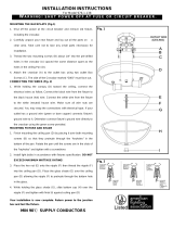
1. Before installing, preset the NIPPLE length:
a) Thread the HEX NUT A onto the NIPPLE, and screw the NIPPLE into the COUPLING on
the FIXTURE PAN a minimum of four turns.
b) Place the center holes of the GLASS SHADE over the NIPPLE and adjust the NIPPLE so
that it protrudes out of the PLASTIC WASHER and HEX NUT B 1/4”. Remove the GLASS
SHADE, PLASTIC WASHER and HEX NUT B and secure the NIPPLE to the COUPLING in
place by tightening the HEX NUT A.
2. Pull the SUPPLY WIRES and the SUPPLY GROUND WIRE from the JUNCTION BOX;
attach the CROSSBAR to JUNCTION BOX, using the JUNCTION BOX SCREWS through
the slotted holes on the CROSSBAR.
3. Thread the FIXTURE SCREWS two full turns into the appropriate threaded holes in the
CROSSBAR. (Check the CROSSBAR against the fixture KEYHOLE SLOTS to ensure proper
fit.)
4. Make the wiring connection: Connect FIXTURE GROUND WIRE to SUPPLY GROUND
WIRE with a wire nut, Attach them to the CROSSBAR with the GREEN GROUND SCREW.
Connect the BLACK SUPPLY WIRE to the BLACK FIXTURE WIRE and WHITE SUPPLY
WIRE to the WHITE FIXTURE WIRE with WIRE NUTS.
5. Carefully tuck all wiring back into the JUNCTION BOX. Lift the FIXTURE PAN over the
JUNCTION BOX, positioning the FIXTURE SCREW heads through the large openings of the
KEY HOLE SLOTS. Rotate the FIXTURE PAN until the FIXTURE SCREW heads are seated
at the small ends of the KEYHOLE SLOTS, secure them with a screwdriver.
6. Install the BULBS (sold separately).
ASSEMBLY AND INSTALLATION (CONT.)
Customer Service 1-800-558-8700
IF IN DOUBT ABOUT ELECTRICAL INSTALLATION,
CONSULT A LICENSED ELECTRICIAN.
556654
7. Carefully lift the GLASS SHADE to the FIXTURE PAN/. Align and pass the NIPPLE through
the center hole in the bottom of the GLASS SHADE. Thread the PLASTIC WASHER and
HEX NUT B at the bottom of the NIPPLE.
8. Thread the FINIAL onto the end of NIPPLE protruding from the HEX NUT B.
9. Restore electric power to installation point ON. Retain this sheet for future reference.
/