Page is loading ...

64-378-14, Rev. D
Technical Bulletin A-4400
Issue Date 0316
© 2016 Johnson Controls, Inc. 1
Part No. 64-378-14, Rev. D
Code No. LIT-718050T
INTRODUCTION 3
Product Overview 3
INSTALLATION PROCEDURES 4
Location 4
Unpacking the Unit 4
Conventional Wall Mounting Arrangement 4
Air Connections 5
Base Mounting Arrangement 6
Activated Carbon Filter Installation 6
Drain Connections 7
Permanent Wiring Using Conduit 8
Wiring to Air Compressor 9
COMMISSIONING 10
Gauge Correction 10
Evaporator Pressure Adjustment 10
Altitude Compensation 10
Low Ambient Temperature Compensation 11
SERVICING PROCEDURES 12
Particle Filter 12
Coalescing Oil Removal Filter 13
A-4400 Series Refrigerated Air Dryers
Installation and Maintenance

2 Air Dryers—A-4400 Series Technical Bulletin
Replacement Coalescing Oil Removal Filter Element Kit 14
Activated Carbon Oil Vapor Removal Filter 15
Pressure Reducing Valve 15
Power On/Fail Lamp 15
Refrigeration Service 16
Condenser Fan Motor Replacement 21
Condenser 23
Air Dryer Compressor Motor Wiring Circuit 23
Excessive Vibration 24
SPECIFICATIONS 25
REPAIR INFORMATION 26

Air Dryers—A-4400 Series Technical Bulletin 3
Introduction
The A-4400 Series Refrigerated Air Dryers are designed for continuous
operation to supply dry air to pneumatic control systems. All components
are selected and assembled to provide dependable service over a long
period of time with a minimum amount of maintenance.
Note: For units without a factory mounted Air Purification System
(consisting of a coalescing oil removal filter with integral
pressure drop indicator, packed column type activated carbon oil
vapor removal filter, service bypass valve, pressure reducing
valve, safety relief valve, and power on/fail lamp), a properly
configured system must include a coalescing oil removal filter as
well as an activated carbon oil vapor removal filter as outlined in
Product Data A-4000 and the Installation and Service Manual for
PureFlow™ Air Compressors (Publication No. 2629).
Table 1: Ordering Data
Code
Number
Flow Capacity at
Rated Condition*
scfm
(L/s)
Air
Purification
System
Shipping
Weight
lb**
A-4412-1
12
(5.7)
Yes 72
A-4412-2
12
(5.7)
No 67
A-4417-1
17
(8.0)
Yes 78
A-4417-2
17
(8.0)
No 73
A-4423-1
23
(10.9)
Yes 78
A-4423-2
23
(10.9)
No 72
* The rated condition is 20 psig (140 kPa) supply pressure, 100
°F (38°C)
saturated inlet air temperature, 100°F ambient temperature, and 80 psig
(560 kPa) inlet pressure.
** lb x 0.454 = kg.
Product
Overview

4 Air Dryers—A-4400 Series Technical Bulletin
Installation Procedures
The A-4400 Series Refrigerated Air Dryer must be located in an open area
that will permit free circulation of air through the ends of the unit. The
A-4400 requires 12 in. (305 mm) top clearance (as measured from the top
of the cabinet) and 12 in. clearance at either end. When the unit is wall
mounted, it is recommended that there also be 10 in. (254 mm) bottom
clearance.
Hand protection is required when removing the A-4400 from its shipping
carton. Proceed as follows:
1. Cut the two adjacent corners of the front carton panel from top to
bottom, then fold the panel down. Remove the air dryer from its
shipping carton through the exposed side.
2. Wearing proper eye protection and using a pair of wire cutters, reach
into the air connection side of the air dryer and cut the steel packing
band securing the compressor to the shipping chipboard.
3. Tip the air dryer slightly on its edge and carefully remove the steel
packing band and discard. Also slide the shipping chipboard out and
discard.
4. Remove and discard the packaging cardboard from behind the
coalescing filter, if applicable (Models A-4412-1, A-4417-1, and
A-4423-1).
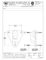
Two key slots are provided at the rear of the A-4400 for wall mounting the
unit (refer to Figure 1). Install the bolts and appropriate anchors
(field furnished) in the wall at 16 in. (406 mm) center-to-center spacing, in
a level arrangement. Hang the A-4400 on the bolts and tighten as
required.
Note: The key slots (center to center spacing) can be hand adjusted
approximately 1/2 in. (13 mm) if needed when hanging the unit on
the mounting bolts.
This wall mounting arrangement provides proper air circulation, allows
easy access to the interior of the unit, and makes it convenient to remove
the particle filter and automatic condensate drain trap assembly through
the bottom of the unit for any necessary cleaning or replacement.
Location
Unpacking the
Unit
Conventional
Wall Mounting
Arrangement

Air Dryers—A-4400 Series Technical Bulletin 5
Capped High Pressure Connection
for High Pressure Riser
(Models with a Factory Mounted Air Purification System)
12-15/16
329
17-1/2
445
21-3/4
552
22-1/16
560
A-4412-1: A-4417-1 and A-4423-1:
12-5/8
321
23-3/16
589
A-4412-1:
18-1/16
459
A-4417-1 and
A-4423-1:
Note: The A-4400 requires 12 in. (305 mm)
top clearance and 12 in. clearance
on either end. When wall mounting
the A-4400, 10 in. (254 mm) bottom
clearance is recommended.
Also, attach the 3/8 in. discharge main
air line to the PRV before mounting.
In
Out
Key Slots
(Two Locations)
for 1/4 in. Bolts
(Field Furnished)
16
406
+
+
14-1/4
362
Figure 1: A-4400 Series Refrigerated Air Dryer Shown with
Optional Factory Mounted Air Purification System
Dimensions
in.
mm
The high pressure side of the compressed air line, after the compressor
tank, must be connected to the 3/8 in. compression inlet air connection.
On models with an optional factory mounted Air Purification System, this
inlet air connection is located on the service bypass valve. These models
also include a capped high pressure outlet connection (refer to Figure 1)
directly ahead of the PRV. To use this connection, remove the cap and
connect the high pressure outlet line to the 3/8 in. compression connection
provided. Check all air line connections for leakage.
Air
Connections

6 Air Dryers—A-4400 Series Technical Bulletin
Several mounting hole patterns are provided in the base of the A-
4400 (refer to Figure 2) for securing the unit to a platform. These
mounting holes are sized for 1/4-20 self-tapping screws or a No.
12 nut and bolt combination (all field furnished).
Figure 2: DryFlow A-4400 Series Refrigerated Air Dryer
Base Mounting Hole Patterns (Plan View)
Dimensions
in.
mm
On models with an optional factory mounted Air Purification System, the
activated carbon oil vapor removal filter is packaged separately within the
dryer shipping carton and must be installed on the unit in the field as
follows:
1. Referring to Table 2, note the life of the activated carbon oil vapor
removal filter element being installed.
2. Divide the element life noted in Step 1 by the average system scfm or
L/s to obtain the expected life in days.
Base Mounting
Arrangement
Mounting Holes
(Eight Locations)
for 1/4-20
Self-tapping Screws
or a No. 12 Nut and
Bolt Combination
(All Field Furnished)
11/16
17
10-7/8
276
5-1/2
140
13-11/16
348
9-11/32
237
7-1/2
191
Activated
Carbon Filter
Installation

Air Dryers—A-4400 Series Technical Bulletin 7
3. Use the expected life calculated in Step 2 to determine the
replacement date, and record this date on the servicing label on the
carbon filter element.
4. Remove the red plastic dust cap from the carbon filter pipe
connection.
5. With the black sealing washer in position on the base of the carbon
filter element, screw the element onto the male pipe thread and hand
tighten to complete the installation.
Table 2: Carbon Filter Element Life
Carbon Filter Element
Code Number
Flow
Capacity
Element Life
A-4000-147
10 scfm (4.7 L/s) 4,000 scfm-Days (1,888 L/s-Days)
A-4000-146
20 scfm (9.4 L/s) 13,000 scfm-Days (6,136 L/s-Days)
The automatic condensate drain trap assembly has a 1/8 in. internal NPT
drain connection and the coalescing oil removal filter assembly
(on air dryers with an optional factory mounted Air Purification System)
has a 1/8 in. external NPT drain connection. Two styles of couplers are
available for connecting the drain line to the coalescing oil removal filter
assembly if needed: the F-400-20 kit is a 1/8 in. external NPT x 1/8 in.
internal NPT coupler, and the F-400-10 kit is a 1/8 in. internal
NPT x 1/4 in. O.D. compression coupler. Both coupler kits must be
ordered separately.
Attach tubing to the connections on the automatic condensate drain trap
assembly and the coalescing oil removal filter assembly (if present),
keeping the runs as short as practical in order to reduce back pressure on
the automatic drains. Use separate drain lines for the automatic
condensate drain and the coalescing oil removal filter drain; never connect
the lines together.
Note: An override feature is incorporated in the coalescing oil removal
filter and automatic condensate drain trap, which allows manual
draining of the bowl. To activate the override, it will be necessary
to remove the tubing and connections from the 1/8 in. NPT drain
connection at the bottom of the bowl. Then, using a 1/8 in.
diameter or smaller rod, insert it up into the drain connection until
it contacts the override needle. This will cause the bowl to drain.
When the bowl has been drained, replace the connections and
tubing.
Drain
Connections

8 Air Dryers—A-4400 Series Technical Bulletin
All A-4400 Series Refrigerated Air Dryers are furnished with a
cord and plug to fit a standard 115 volt receptacle. If permanent
wiring is required using conduit, proceed as follows:
1. Cut the line cord to a sufficient length so that it will reach
from the compressor terminal box through Hole 1 as illustrated in
Figure 3; 12 in. (305 mm) should be long enough.
2. Strip the wires back approximately 1 in. (25 mm).
3. Attach the strain relief bushing (provided with each unit) to the line
cord approximately 3 in. (76 mm) from the cut end and insert it into
Hole 1.
4. Connect the conduit to Hole 2 as illustrated in Figure 3, and join the
leads together using the appropriate wire nuts (field furnished).
Figure 3: Permanent Wiring Using Conduit
Permanent
Wiring Using
Conduit

Air Dryers—A-4400 Series Technical Bulletin 9
Wiring may be run through the load side of the air compressor disconnect
switch ahead of the Pressure Electric (PE) switch, as illustrated in
Figure 4. Doing so will allow continuous A-4400 operation whenever the
disconnect switch is closed, while control over the air compressor is
retained by the PE switch.
Note: The air dryer motor voltage must match the air compressor motor
voltage in order to wire the unit as illustrated in Figure 4.
Figure 4: Single-Phase Air Compressor Motor
Wiring to Air
Compressor
115 VAC
60 Hz
Air Compressor
Disconnect
Pressure
Switch
Air Compressor
Air
Dryer

10 Air Dryers—A-4400 Series Technical Bulletin
Commissioning
The evaporator pressure gauge is calibrated to a test gauge at the factory.
Readings are recorded on a label inside the dryer cabinet base. Apply this
correction to the evaporator gauge to obtain a precise reading.
The A-4400 Series Refrigerated Air Dryers are factory set to protect
against air side freeze-up down to ambient temperatures of 40°F (4°C) and
altitudes up to 1500 ft.
Using the corrected no load evaporator pressure gauge reading and current
ambient temperature, refer to the graph in Figure 5 to determine if the
evaporator pressure is at the proper setting. If the value is within the
acceptable operating zone as shown on the graph, then no further
adjustments are necessary. If the value is not within the acceptable
operating zone, then it will be necessary to adjust the expansion valve.
Refer to the Refrigeration Service section and follow Steps 1 through 5
(readjusting the expansion valve setting) to properly adjust the expansion
valve until the evaporator pressure gauge is at the adjusted pressure.
Note: All of the expansion valve settings are based on no load
conditions, position the service bypass valve into the bypass mode.
Allow the unit to run unloaded a minimum of 10 minutes prior to
checking evaporator pressure or adjusting the expansion valve.
If the air dryer is installed in high altitudes, the expansion valve will
have to be adjusted to compensate for the new ambient pressure.
For altitudes from 1500 to 5000 ft, increase the expansion valve setting by
2.5 psig (17.5 kPa), and for altitudes over 5000 ft, increase the expansion
valve setting by 4.0 psig (28 kPa). This increase in evaporator pressure
must be added to the value determined by the graph in Figure 5 to account
for altitude effects. Refer to the Refrigeration Service section and follow
Steps 1 through 5 (readjusting the expansion valve setting) to properly
adjust the expansion valve until the evaporator pressure gauge is at the
adjusted pressure.
Example:
If: Altitude = 4000 ft above sea level
Ambient temperature = 80°F
Evaporator pressure gauge reading at no load condition = 34.8 psig
Then: Corrected evaporator pressure = 34.8 psig + 2.5 psig = 37.3 psig
Gauge
Correction
Evaporator
Pressure
Adjustment
Altitude
Compensation

Air Dryers—A-4400 Series Technical Bulletin 11
Ambient Temperature (°F)
Evaporator Pressure (psig)
28
26
36
34
32
30
38
40
39
41
42
43
37
35
33
31
29
27
40 50
60
70 80 90 100 110 120 130
Acceptable Operating Zone
Nominal Setting
Figure 5: Evaporator Pressure vs. Ambient Temperature
(Sea Level--No Load Condition)
If the air dryer is used in ambient conditions between 35 and 40°F
(2 and 4°C) the expansion valve must be adjusted to increase the expansion
valve gauge pressure by 3 psig (21 kPa) to offset a possible freeze-up
condition. This increase in evaporator pressure must be added to the value
determined by the graph in Figure 5 to account for low ambient temperature
effects. At high altitudes and low ambient temperatures, it will be necessary
to add both pressure corrections and readjust the expansion valve. Refer to the
Refrigeration Service section and follow Steps 1 through 5 (readjusting the
expansion valve setting) to properly adjust the expansion valve until the
evaporator pressure is at the adjusted pressure. Operation of the A-4400 in
ambient temperatures below 35°F (2°C) is not recommended.
Note: If it was necessary to adjust the expansion valve settings and position
the service bypass valve to bypass the air dryer, then return the service
bypass valve to normal mode in order to resume operation. Also, if
the pressures were changed from the normal settings, indicate the
changes on the air dryer to facilitate future service.
Low Ambient
Temperature
Compensation

12 Air Dryers—A-4400 Series Technical Bulletin
Servicing Procedures
The A-4400 Series Refrigerated Air Dryer is equipped with an automatic
condensate drain trap assembly with a particle filter. The particle filter
should be replaced annually or whenever the filter element appears dirty.
To replace the particle filter element and/or automatic drain valve, refer to
Figure 6 and proceed as follows:
1. Remove the service bypass valve locking pin and push the plunger to
the right into the bypass position. Doing so will unload the pressure
in the drain bowl.
2. Turn the filter bowl counterclockwise and remove. Also remove
the O-ring .
3. Visually inspect the filter bowl for signs of cracking. If the bowl is
cracked, it is necessary to replace the complete assembly
(See Table 3, Item E ordered separately). If the bowl is not cracked,
clean it using a liquid household detergent.
4. Turn the baffle counterclockwise and remove.
5. Remove the old particle filter element and discard.
6. Install the new particle filter element (See Table 3, Item E ordered
separately). Screw the baffle into the filter body until contact is
made with the filter element , then tighten an additional 1/4 turn.
7. To replace the auto drain (See Table 3, Item E ordered separately),
remove the drain retaining nut , invert the bowl, and remove and
discard the float and seal .
8. Install the new seal and float and tighten the drain retaining
nut to approximately 25 in
.
lb of torque.
9. Reinstall the filter bowl and O-ring . Return the service bypass
valve to normal operation by pushing the plunger left to its original
position. Reinstall the locking pin to ensure that the plunger remains
positioned for normal operation.
Particle Filter

Air Dryers—A-4400 Series Technical Bulletin 13
1
4
3
2
8
7
6
5
Figure 6: Particle Filter/Auto Drain Replacement
The coalescing oil removal filter is equipped with an automatic drain for
discharging accumulations of entrapped liquids. This filter also features a
pressure drop indicator integral to the top of the unit (refer to Figure 7).
On a new filter, this indicator is green in color. As the pressure drop
across the filter increases, a slide within the indicator moves, bringing
some red color into view. When the pressure drop reaches 7.5 psig
(52.5 kPa), the indicator becomes entirely red, indicating that the filter
element needs to be replaced. Even if the indicator is not entirely red, it is
recommended that the filter element be replaced annually.
Coalescing Oil
Removal Filter

14 Air Dryers—A-4400 Series Technical Bulletin
Note: Even if the indicator
is not entirely red,
it is recommended
that the filter element
be replaced annually.
Universal
O-ring Kit
Complete
Assembly
Coalescing
Filter Element,
and O-rings
Replacement
Drain Valve
Pressure Drop
Indicator
Figure 7: Coalescing Oil Removal Filter
Each kit includes one replacement filter element, one filter element
O-ring, and one filter bowl O-ring (refer to Figure 7). To replace the filter
element, proceed as follows:
1. Remove the service bypass valve locking pin, and push the plunger to
the right into the bypass position. Doing so will unload the pressure
in the filter bowl.
2. Disconnect the drain tubing.
3. Depress the lever on the filter bowl clamp, and turn it 1/8 revolution
in either direction. Drop the metal bowl guard and bowl to expose the
filter element.
Replacement
Coalescing Oil
Removal Filter
Element Kit

Air Dryers—A-4400 Series Technical Bulletin 15
4. Viewing the old filter from the bottom, turn the element
counterclockwise to remove it.
5. Clean the small screen around the drain seat of the automatic drain
valve by turning the filter bowl upside down and tapping it lightly.
6. Visually inspect the bowl for signs of cracking. If the bowl is
cracked, it will be necessary to replace the complete assembly
(A-4000-1048 or A-4000-1049 ordered separately). If the bowl is not
cracked, clean it and the drain valve assembly using a liquid
household detergent.
7. Install the new filter element and connect the drain. For optimal
filtering performance, it is recommended that the filter element be
presoaked with clean oil.
8. Return the service bypass valve to normal operation by pushing the
plunger left to its original position. Reinstall the locking pin to ensure
that the plunger remains positioned for normal operation.
Refer to the white service label on the activated carbon filter element
being replaced for the proper replacement procedure.
After the activated carbon filter element has been replaced, apply the
white service label included with the new element, and record the next
replacement date (month and year). Determine this date following the
procedure outlined earlier in the Activated Carbon Filter Installation
section.
Upon system startup, the output of the pressure reducing valve would be
approximately 15 to 20 psig (105 to 140 kPa).
Note: For optimal performance, it is suggested that the pressure
reducing valve be readjusted at the normal system flow rate.
To adjust this pressure, pull up on the black knob and turn until the
desired pressure is read on the low pressure gauge. Push down on the
knob to lock the desired pressure setting. The safety relief valve is factory
set at approximately 33 psig (231 kPa).
The power on/fail lamp is located below the coalescing oil removal filter.
The lamp is ON (illuminated) when there is power to the A-4400 and the
compressor overload relay is closed (no overload condition exists). If the
air dryer is running and the power on/fail lamp is OFF, the lamp will need
to be replaced as follows:
1. Disconnect the power supply to the air dryer.
2. Cut the two leads leaving behind a convenient length of wire for use
with the replacement bulb.
Activated
Carbon Oil
Vapor Removal
Filter
Pressure
Reducing Valve
Power On/Fail
Lamp

16 Air Dryers—A-4400 Series Technical Bulletin
3. Slide the old lamp forward out of its cutout and discard; a pliers may
be required.
4. Splice the replacement bulb to the existing leads using wire nuts (field
furnished).
5. Slide the replacement lamp (A-4300-602 ordered separately) into the
cutout and push in until it reaches the chrome stop.
6. Reconnect the power supply to the air dryer.
7. Check that the lamp is illuminated when the compressor is running.
Note: Due to the extremely small refrigerant charge in these units
(as noted on the unit nameplate), the service valve should only be
used when evacuating and recharging the unit. When removing
charging equipment from the service valve, care must be taken to
avoid releasing any amount of refrigerant. The integral evaporator
pressure gauge (with its gauge correction) on each unit should be
used for all service procedures.
The A-4400 is factory set to follow the Evaporator Pressure vs. Ambient
Temperature curve illustrated in Figure 5. If at no load, the evaporator
pressure rises above the acceptable operating zone, one or more of the
following conditions may exist.
• The ambient temperature or the air flow may be above the specified
limits.
• The expansion valve may be out of adjustment or stuck in the open
position.
• The condenser may be dirty.
• The condenser fan motor may be inoperative.
• The compressor may be inoperative.
If the evaporator pressure is below the acceptable operating zone
(refer to Figure 5) then either the expansion valve is out of adjustment
or the refrigerant charge is low.
If it is necessary to readjust the expansion valve, proceed as follows:
1. Switch the service bypass valve in order to bypass the dryer. Allow
the unit to run unloaded a minimum of 10 minutes prior to adjusting
the expansion valve.
2. Remove the cover from the dryer.
Refrigeration
Service

Air Dryers—A-4400 Series Technical Bulletin 17
3. Turn the expansion valve adjusting screw to provide an evaporator
pressure that corresponds to the ambient temperature determined in
Figure 5. Turning the screw clockwise increases the pressure;
counterclockwise decreases the pressure. One complete revolution
(360 degrees) equals a pressure change of approximately 10.5 psi
(73.5 kPa).
Note: If when adjusting the screw clockwise and counterclockwise,
the expansion valve does not respond and the evaporator
pressure remains high, a foreign object may be lodged in the
expansion valve orifice. To clear the orifice, turn the
expansion valve adjusting screw clockwise as far as possible,
taking note of the number of revolutions made. Then return
the screw counterclockwise to its original position and check
the evaporator pressure.
4. Allow 20 minutes running time to stabilize the system, then reset the
refrigerant pressure if required.
If after adjusting the expansion valve setting, the evaporator pressure is
still too low, the refrigerant charge is probably low. To recharge the
system, proceed as follows:
1. Disconnect the power supply to the air dryer.
2. Remove the filter bowl and test for possible internal refrigerant leaks
by allowing a small amount of supply air to pass through the unit.
Check for traces of gaseous refrigerant in the escaping air using a
HFC-134a detector at the condensate drain trap (refer to Figures 10
and 11). If an internal leak is discovered, unit replacement is
required. Reinstall the filter bowl when testing has been completed.
3. Using a HFC-134a detector, test for possible external refrigerant
leaks, paying particular attention to all solder joints. If an external
leak is discovered, proceed as follows:
Note: The service valve (as illustrated in Figures 8 and 9) provides
access to the evaporator for checking or servicing. The
service valve is a Schrader type valve with a sealing cap.
To use the valve, unscrew the cap to expose the Schrader
valve pin.
a. Use a vacuum pump to evacuate the unit of all refrigerant into an
approved refrigerant receptacle before repairing leaks.
b. Repair any external leaks found using hard solder and flux.

18 Air Dryers—A-4400 Series Technical Bulletin
4. Using a vacuum pump, evacuate any remaining air and moisture.
5. Charge the unit with R-134a refrigerant to within 1/4 ounce of the
amount specified on the air dryer nameplate.
6. Remove the charging manifold and replace the cap securely on the
service valve.
7. Reinstall the A-4400 cover and reconnect the power supply to the air
dryer.
8. If the evaporator pressure (gauge reading plus correction) does not
return to normal as illustrated in Figure 5, adjust the expansion valve
as described in the Refrigeration Service section.
Cap
Figure 8: Service Valve Detail for Access to Evaporator

Air Dryers—A-4400 Series Technical Bulletin 19
Figure 9: A-4400 Series Refrigerated Air Dryer with Cover Removed

20 Air Dryers—A-4400 Series Technical Bulletin
Figure 10: Schematic of A-4400 Series Refrigerated Air Dryer with Service Bypass
Valve Positioned for Normal Operation
(Shown with Optional Factory Mounted Air Purification System)
Figure 11: Schematic of A-4400 Series Refrigerated Air Dryer with Service Bypass
Valve in Bypass Position
(Shown with Optional Factory Mounted Air Purification System)
L
in
e
Voltage
Service
V
al
ve
Heat
E
x
ch
an
g
er
Tube
-
I
n
-
T
u
b
e
Counterflow
E
v
ap
or
a
to
r
A
u
to
E
x
p.
V
al
v
e
A
u
to
matic
Co
n
de
ns
a
te
D
r
ai
n
T
ra
p
Discharge Line
Suction Line
Inlet From
Air Compressor
PRV
With Low
P
re
s
su
re
G
au
ge
Hi
gh
Pr
es
s
ur
e
Output
Re
g
ul
at
e
d
Outp
u
t
S
a
fe
ty
Re
li
e
f
Valve
Coalescing
Oi
l
R
em
o
va
l
Fi
lt
e
r
Wi
t
h
Automatic
Drain
Ac
ti
v
at
e
d
Carbon
Oil Vapor
Re
mo
v
al
Fi
lt
e
r
E
va
po
r
at
or
Pressure
G
auge
Condenser
Service Bypass
V
al
ve
Line
Voltage
Service
Valve
Heat
Exchanger
Tube-In-Tube
Counterflow
Evaporator
Auto Exp.
Valve
Automatic
Condensate
Drain Trap
Discharge Line
Suction Line
Inlet From
Air Compressor
PRV
With Low
Pressure
Gauge
High Pressure
Output
Regulated
Output
Safety Relief
Valve
Coalescing
Oil Removal
Filter With
Automatic
Drain
Activated
Carbon
Oil Vapor
Removal
Filter
Evaporator
Pressure
Gauge
Exhaust
Condenser
Service
Bypass
Valve
/