Page is loading ...

INSTALLATION INSTRUCTIONS
AND USER MANUAL
RESIDENTIAL USE ONLY
INSTALLER: LEAVE THIS MANUAL WITH THE HOMEOWNER.
HOMEOWNER: USE AND CARE INFORMATION
ON PAGES 28 and 32 to 36.
READ AND SAVE THESE INSTRUCTIONS
04313 rev C
MODELS
VB0061
HEPA 2000*
HF 2.0*
HEPA 3000*
HF 3.0*
HEPA 4000*
HEPA 1000*
HF 1.0*
*Patents pending
NOTE: HEPA 4000 model available in United States only.

ABOUT THIS MANUAL
First, we want to congratulate you on your purchase of this excellent unit which will
allow you and your family to enjoy clean and health
y air throughout your home for
years to come!
Because of the large amount of models covered by this publication, the illustrations
are typical ones. Some details of your unit may be slightly different than the ones
shown.
Please take note that this manual uses the following symbols to emphasize
particular information:
NOTE: Indicates supplementary information needed to fully complete an instruction.
We welcome any suggestions you may have concerning this manual and/or the
unit, and we would appreciate hearing your comments on ways to better serve you.
Please contact us by phone at one of the following numbers:
Exclusiv
ely for all HF Models: Exclusively for all HEPA Models:
Broan-NuTone Canada Inc. Venmar Ventilation inc.
1 866 737-7770 1 800 567-3855
WARNING
Identifies an instruction which, if not followed, might cause serious
personal injuries including possibility of death.
0
!
CAUTION
Denotes an instruction which, if not followed, may severely damage the unit
and/or its components.
- 2 -

!
- 3 -
TO REDUCE THE RISK OF FIRE, ELECTRIC SHOCK, OR INJURY TO
PERSON(S) OBSERVE THE FOLLOWING:
1. This unit is intented for residential installation only.
2. Use this unit only in the manner intended by the manufacturer. If you have
questions, contact the manufacturer at the address or telephone number listed
in the warranty.
3. Before replacing filters, servicing or cleaning unit, disconnect power cord from
electrical outlet.
4. Installation must be done in accordance with all applicable codes and standards,
including fire-rated construction codes and standards.
5. This unit is not designed to provide combustion and/or dilution air for fuel-burning
appliances.
6. When cutting or drilling into wall or ceiling, do not damage electrical wiring and
other hidden utilities.
7. Do not use this unit with any solid-state speed control device other than
optional wall controls C12, CM, C34 and CMR (sold separately).
8. This unit must be grounded. The power supply cord has a 3-prong grounding
plug for your personal safety. It must be plugged into a mating 3-prong grounding
receptacle, grounded in accordance with the national electrical code and local
codes and ordinances. Do not remove the ground prong. Do not use an
extension cord.
9. Do not install in a cooking area or connect directly to any appliances.
10. Do not use to exhaust hazardous or explosive materials and vapors.
CAUTION
1. To avoid prematurate clogged filters, turn OFF the unit during construction or
renovation.
2. Please read specification label on product for further information and requirements.
3. For HEPA 2000, HF 2.0, HEPA 3000, HF 3.0 and HEPA 4000 units only: Be
sure to duct air outside – Do not intake / exhaust air into spaces within walls
or ceiling or into attics, crawl spaces, or garage.
4. Itended for residential installation only in accordance with the requirements of
NFPA 90B.
5. Do not run any air ducts directly above or closer than 2 ft (0.61 m) to any furnace
or its supply plenum, boiler, or other heat producing appliance. For HEPA 2000,
HF 2.0, HEPA 3000, HF 3.0 and HEPA 4000 units only, if a duct has to be
connected to the furnace return plenum, it must be connected not closer than
9’10” (3 m) from this plenum connection to the furnace. For HEPA 1000 and
HF 1.0 units only, the distance must be not closer than 2’ (0.61 m).
6. The ductwork is intended to be installed in compliance with all local and
national codes that are applicable.
WARNING
ABOUT THESE UNITS

1.0 BEFORE STARTING . . . . . . . . . . . . . . . . . . . . . . . . . . . .6
1.1 Inspect the Content of the Boxes . . . . . . . . . . .. . 6
2.0 TYPICAL INSTALLATIONS . . . . . . . . . . . . . . . . . . . . . . . .6
2.1 HEPA 1000 and HF 1.0 Unit Installations . . . . . . 7
2.1.1 Stand Alone . . . . . . . . . . . . . . . . . . . . . . . . . .7
2.1.2 Central Draw Point . . . . . . . . . . . . . . . . . . . . .8
2.1.3 Return-to-Return Installation . . . . . . . . . . . . . . . .9
2.2 Installations for HEPA 4000 Only . . . . . . . . . . . .10
2.2.1 Geographical Location . . . . . . . . . . . . . . . . .10
2.2.2 HEPA 4000 Attic Installation . . . . . . . . . . . . . .11
2.3 HEPA 2000, HF 2.0, HEPA 3000, HF 3.0
and HEPA 4000 Unit Installations . . . . . . . . . . . .12
2.3.1 Stand Alone . . . . . . . . . . . . . . . . . . . . . . . . .12
2.3.2 Central Draw Point . . . . . . . . . . . . . . . . . . . .13
2.3.3 Return-to-Return Installation . . . . . . . . . . . . . . .14
3.0 DIMENSIONS . . . . . . . . . . . . . . . . . . . . . . . . . . . . . .15
3.1 HEPA 1000 and HF 1.0 Units . . . . . . . . . . . . . .15
3.2 HEPA 2000, HF 2.0, HEPA 3000, HF 3.0
and HEPA 4000 units . . . . . . . . . . . . . . . . . . . .15
3.3 Mounting and Servicing Considerations . . . . . . . .16
4.0 INSTALL THE UNIT . . . . . . . . . . . . . . . . . . . . . . . . . . .17
4.1 Locating and Mounting the Unit . . . . . . . . . . . . .17
4.2 Mount the Ports on the Unit . . . . . . . . . . . . . . . .17
4.3 How to Hang the Unit . . . . . . . . . . . . . . . . . . .18
4.4 Planning of the Ductwork . . . . . . . . . . . . . . . . .19
4.5 Installing Ductwork and Registers . . . . . . . . . . . .20
4.5.1 Stand Alone System . . . . . . . . . . . . . . . . . . .20
4.5.2 Central Draw Point . . . . . . . . . . . . . . . . . . . .21
4.5.3 Return-to-Return . . . . . . . . . . . . . . . . . . . . . .22
TABLE OF CONTENTS
- 4 -

4.6 Installation des conduit flexibles isolés . . . . . . . . .23
4.6.1 Raccordement à la transition Tandem® . . . . . .23
4.6.2 Raccordement aux bouches ovales de 5”à 6” . .24
4.7 Installation de la bouche extérieure double . . . . . .25
4.7.1 Assemblage de la bouche extérieure double . . .25
4.7.2 Localisation de la bouche extérieure double . . .25
4.7.3 Raccordement de la transition Tandem®
à la bouche extérieure double . . . . . . . . . . . . .25
4.8 Raccordement du boyau de drainage . . . . . . . . .27
5.0 CONTRÔLES . . . . . . . . . . . . . . . . . . . . . . . . . . . . . . .28
5.1 Interrupteur principal . . . . . . . . . . . . . . . . . . . .28
5.2 Contrôle muraux optionnels . . . . . . . . . . . . . . . .28
5.3 Dimensions . . . . . . . . . . . . . . . . . . . . . . . . . .28
5.4 Installation des contrôles muraux optionnels . . . . .29
5.5 Fonctionnement du contrôle C12 / CM . . . . . . . .32
5.5.1 Description du contrôle C12 / CM . . . . . . . . .32
5.5.2 Utilisation du contrôle C12 / CM . . . . . . . . . .32
5.6 Fonctionnement du contrôle C34 / CMR . . . . . . .33
5.6.1 Description du contrôle C34/ CMR . . . . . . . .33
5.6.2 Utilisation du contrôle C34 / CMR . . . . . . . . .33
6.0 ENTRETIEN . . . . . . . . . . . . . . . . . . . . . . . . . . . . . . .34
6.1 Entretien semestriel . . . . . . . . . . . . . . . . . . . . . .34
6.2 Entretien annuel . . . . . . . . . . . . . . . . . . . . . . .36
6.3 Réinitialisation générale . . . . . . . . . . . . . . . . . . .36
7.0 PIÈCES DE SERVICE . . . . . . . . . . . . . . . . . . . . . . . . . .37
8.0 D
ÉPANNAGE . . . . . . . . . . . . . . . . . . . . . . . . . . . . . .38
TABLE DES MATIÈRES
- 5 -

1. BEFORE STARTING
1
.1 INSPECT THE CONTENTS OF THE BOXES
• Inspect the exterior of the unit for shipping damage. Ensure that there is
no damage to the door, door latches, main switch, etc.
• Inspect the interior of the unit for damage. Ensure that blower assembly, heat
recovery core (HEPA 3000 et HF 3.0), energy recovery core (HEPA 4000),
insulation, dampers (HEPA 2000, HF 2.0, HEPA 3000, HF 3.0 and HEPA 4000),
prefilter, HEPA filter, etc. are all intact.
- 6 -
2. TYPICAL INSTALLATIONS
Installations may vary according to the model number and the position in which
the unit is installed. Use the following illustrations as guidelines to help you decide
on how your unit will be installed.
All the units should be hung to the joist, and installed either vertically or
horizontally. NOTE: For more details, see Point 5.3 in Section 5 INSTALL THE
UNIT.
In every case, bathroom fans and a range hood should be used to exhaust stale
air. Also, for homes with more than one level, we recommend one exhaust
register at the highest level.
There are 3 installation methods: Stand Alone, Central Draw Point and Return-to-
Return Installation.
NOTE: An electrical outlet has to be available within 3 feet from the unit.
CAUTION
Remove the cardboard strip inside the unit (if applicable).
WARNING
To avoid risk of suffocation, discard the plastic bag wrapping the unit.
0
!

- 7 -
2. TYPICAL INSTALLATIONS (CONT’D)
2.1.1 STAND ALONE (Primarily for homes with radiant hot water or electric
baseboard heating.)
Stale air is drawn to the unit by the register located at the highest level of the
house. Filtered air is supplied by the register located at the lowest level.
See figure below.
2.1 HEPA 1000 AND HF 1.0 UNIT INSTALLATIONS

2.1.2 CENTRAL DRAW POINT (CONNECTION TO FORCED AIR SYSTEM)
VH0038
Stale air is drawn to the unit by the register located at the highest level of the
house. Filtered air is supplied to the retur
n (plenum) of the forced air unit.
For this type of installation, it is not essential that the forced air system blower
runs when the unit is in operation, but we recommend it.
See figure below.
NOTE: Home with multiple forced air systems should have 1 unit on each system.
2.1 HEPA 1000 AND HF 1.0 UNIT INSTALLATIONS (CONT’D)
- 8 -
2. TYPICAL INSTALLATIONS (CONT’D)
CAUTION
Do not connect the unit (HEPA 1000 or HF 1.0) on any forced air system supply
duct. Connect it only to the air return duct. Do not install duct or duct
connector directly above the forced air unit or not less than 2’ (0.61 m) of the
plenum connection to the forced air unit, as measured along the length of
the duct.

- 9 -
2.1.3 RETURN-RETURN INSTALLATION (CONNECTION TO A FORCED AIR SYSTEM)
2. TYPICAL INSTALLATIONS (CONT’D)
Filtered air and stale air flow through the forced air system ducts which simplifies
the installation. Filtered air is supplied to the return (plenum) of the forced air unit.
To avoid cross-contamination and achieve highest efficiencies, the f
orced air system
blower must always be ON (or the unit efficiency will be affected).
See figure below.
NOTE: Home with multiple forced air systems should have 1 unit on each system.
CAUTION
Do not connect the unit (HEPA 1000 or HF 1.0) on any forced air system supply
duct. Connect it only to the air return duct. Do not install duct or duct
connector directly above the forced air unit or not less than 2’ (0.61 m) of the
plenum connection to the forced air unit, as measured along the length of
the duct.
2.1 HEPA 1000 AND HF 1.0 UNIT INSTALLATIONS (CONT’D)

2. TYPICAL INSTALLATIONS (CONT’D)
The HEPA 4000 unit was created to meet specific requirements related to
geographic locations. Take a look on the map below. The shaded area shows
where the HEPA 4000 can be installed.
NOTE:The HEPA 4000 unit is designed to assist in the management of humidity
introduced into the home. In extreme humidity conditions, the use of additional
dehumidification may be desirable. Quickly remove all excess moisture and
keep areas clean.
HELENA
OLYMPIA
SALEM
BOISE
BISMARCK
SALT LAKE CITY
ST. PAUL
DES MOINES
MADISON
HARRISBURG
SACRAMENTO
DENVER
TOPEK
A
DETROIT
INDIANAPOLIS
SANTA FE
SPRINGFIELD
OKLAHOMA CITY
PHOENIX
COLUMBUS
NASHVILLE
ATLANTA
BATON ROUGE
AUSTIN
COLUMBIA
RALEIGH
WASHINGTON
HARTFORD
BO
S
RENO
HEPA 4000 RESTRICTED AREA
VN0005A
- 10 -
2.2 INSTALLATION FOR HEPA 4000 ONLY
Never install an HEPA 4000 unit out of the HEPA 4000 restricted area.
CAUTION
2.2.1 GEOGRAPHICAL LOCATION

All 3 types of installation can be used in the attic (Stand Alone, Central Draw Point
or Return-Return). The example shown below is a Return-Return installation
(connection to a forced air system).
VH0051
- 11 -
A portion of stale air is exhausted to the outside and the rest is drawn to the unit.
Outside fresh air is blended with interior air and then filtered. This filtered air is
supplied to the retur
n (plenum) of the forced air unit.
To avoid the cross-contamination and achieve highest efficiencies, the forced air
system blower must always be ON (or the unit efficiency will be affected).
See figure below.
NOTE: Home with multiple forced air systems should have 1 unit on each system.
Do not connect the HEPA 4000 on any forced air system supply duct.
Connect it only to the air return duct. Do not install duct or duct connector
directly above the forced air unit or not less than 9’10’’ (3 m) of the plenum
connection to the forced air unit, as measured along the length of the duct.
CAUTION
Due to the potential temperature difference between the attic and the rest of
the house, all unit ducts must be insulated.
CAUTION
The attic temperature must always be above 0°C (32°F).
CAUTION
2. TYPICAL INSTALLATIONS (CONT’D)
2.2 INSTALLATION FOR HEPA 4000 ONLY (CONT’D)
2.2.2 HEPA 4000 ATTIC INSTALLATION

- 12 -
2.3 HEPA 2000, HF 2.0, HEPA 3000, HF 3.0 AND HEPA 4000
UNIT INSTALLATIONS
2.3.1 STAND ALONE (Primarily for homes with radiant hot water or electric
baseboard heating.)
VH0039
A portion of stale air (coming from the register located at the highest level of the
house) is exhausted to the outside and the rest is drawn to the unit. Outside fresh
air is blended with interior air and then filtered. Fresh filtered air is supplied by the
register located in the lowest livable level. See figure below.
2. TYPICAL INSTALLATIONS (CONT’D)

- 13 -
2.3.2 CENTRAL DRAW POINT (CONNECTION TO A FORCED AIR SYSTEM)
2.3 HEPA 2000, HF 2.0, HEPA 3000, HF 3.0 AND HEPA 4000 UNIT
INSTALLATIONS (CONT’D)
A portion of stale air (coming from the register located in the highest level of the
house) is exhausted to the outside and the rest is drawn to the unit. Outside fresh
air is blended with interior air and then filtered. This filtered air is supplied to the
retur
n (plenum) of the forced air unit.
For this type of installation, it is not essential that the forced air system blower
runs when the unit is in operation, but we recommend it.
See figure below.
NOTE: Home with multiple forced air systems should have 1 unit on each system.
Do not connect the unit (HEPA 2000, HF2.0, HEPA 3000, HF 3.0 or HEPA 4000)
on any forced air system supply duct. Connect it only to the air return duct.
Do not install duct or duct connector directly above the forced air unit or
not less than 9’10’’ (3 m) of the plenum connection to the forced air unit, as
measured along the length of the duct.
2. TYPICAL INSTALLATIONS (CONT’D)
CAUTION

2. TYPICAL INSTALLATIONS (CONT’D)
A portion of stale air is exhausted to the outside and the rest is drawn to the unit.
Outside fresh air is blended with interior air and then filtered. This filtered air is
supplied to the retur
n (plenum) of the forced air unit.
To avoid the cross-contamination and achieve highest efficiencies, the f
orced air
system blower must always be ON (or the unit efficiency will be affected).
The HEPA 2000 and HF 2.0 units need to be ON all the time, since they don’t
have motorized dampers. If these units are OFF, then the forced air unit will draw
outdoor air inside.
NOTE: Home with multiple forced air systems should have 1 unit on each system.
VH0043
- 14 -
2.3.3 RETURN-TO-RETURN INSTALLATION (CONNECTION TO A FORCED AIR SYSTEM)
2.3 HEPA 2000, HF 2.0, HEPA 3000, HF 3.0 AND HEPA 4000 UNIT
INSTALLATIONS (CONT’D)
Do not connect the unit (HEPA 2000, HF2.0, HEPA 3000, HF 3.0 or HEPA 4000)
on any forced air system supply duct. Connect it only to the air return duct.
Do not install duct or duct connector directly above the forced air unit or
not less than 9’10’’ (3 m) of the plenum connection to the forced air unit, as
measured along the length of the duct.
CAUTION

3.2 HEPA 2000, HF 2.0, HEPA 3000, HF 3.0 AND HEPA 4000 UNITS
FRONT VIEW TOP VIEW
- 15 -
3.1 HEPA 1000 AND HF 1.0 UNITS
FRONT VIEW TOP VIEW
17.8''
(452 mm)
29''
(737 mm)
22.9'' (581 mm)
VK0047
29.4''
(748 mm)
VK0048
17.8''
(452 mm)
22.9'' (581 mm)
3. DIMENSIONS

3. DIMENSIONS (CONT’D)
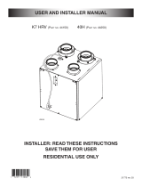
3.3 MOUNTING AND SERVICING CONSIDERATIONS
• The two following pictures are showing the minimum clearance needed
to open the door completely.
22.5” 15.75”
(572 mm) (400 mm)
VD0117
VD0116
22”
(559 mm)
NOTE: A minimum of 8” (203 mm) clearance from any obstruction on top of the
unit is required for the ductwork radius turn.
8”
(203 mm)
VD0118
8 3/4"
222 mm
9 3/4"
248 mm
• The joist opening needed to install the Tandem
®
tansition must be 9 3/4”
(248 mm) minimum. Also, the maximum height of the Tandem
®
transition
is 8 3/4” (222 mm). See Tandem
®
transition end view below.
- 16 -

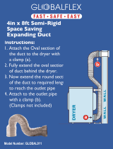
4.2 MOUNT THE PORTS ON THE UNIT
Mount the 8” oval ports and the 5” to 6” oval
ports on the top of the unit using the screws
provided in the hardware box (4 screws
#8 x 3/4” long per port).
NOTES: 1. The HEPA 1000 and the HF 1.0
units don’t have the 5” to 6” oval
ports.
2. If an optional wall control has to be
installed, do not install the front
8’’ oval port at this time.
4. INSTALL THE UNIT
Here are the tools and materials needed to perform the installation:
- Phillips screwdriver #2 or Robertson #1
- Hammer and flat blade screwdriver (for plenum connection installation only, to
make holes in existing metal duct)
- Scissors or utility knife (to cut duct tape)
- Duct tape
- Tin snips or metal shear (for plenum connection installation only, to cut ductwork)
- Aluminum duct tape (for plenum connection installation only)
- Jig saw (except for the HEPA 1000 unit)
- Caulking gun and caulking (except for HEPA 1000 and HF 1.0 units)
- 17 -
VO0018
4.1 LOCATING AND MOUNTING THE UNIT
Choose an appropriate location for the unit.
• Within an area of the house where the ambiant temperature is between 10°C
(50°F) and 65°C (149°F) (basement, furnace room, closet, etc.).
• So as to provide easy access to the interior of the unit, for filter maintenance.
• Close to an exterior wall, so as to limit the length of the insulated flexible
duct to and from the unit (not necessary for HEPA 1000 and HF 1.0 units).
• Away from hot chimneys and other fire hazards.
• Allow for a power source (standard 3-prong grounding outlet).
• Close to a drain. If no drain is close by, use a pail to collect run-off.
(for HEPA 3000 and HF 3.0 units only).

- 18 -
4.3 HOW TO HANG THE UNIT
Use the 4 chains and springs in the hardware pack provided with the unit.
According to your needs, you can install the unit either in vertical or horizontal
position.
VD0074
VERTICAL POSITION - ALL MODELS
HORIZONTAL POSITION (LEFT SIDE)
A
LL MODELS
HORIZONTAL POSITION (RIGHT SIDE)
MODELS HEPA 1000, HF 1.0
HEPA 2000, HF 2.0 AND
HEPA 4000 ONLY
VD0075
VD0076
4. INSTALL THE UNIT (CONT’D)

4.3 HOW TO HANG THE UNIT (CONT’D)
• Turn the switch knob to OFF position in
order to unlock the door. Unlatch the door
and open it. Using a screwdriver, remove
the 2 retaining screws of the front plate and
carefully remove the front plate from the unit.
• Insert the 4 hooks in the square holes and fix them to the
unit using 4 screws #8 - 32 x 3/4”.
NOTE: If an optional wall controll has to be installed, go to
Section 5.0 on pages 29 to 31. If not, continue the installation.
• Reinstall the front plate and close the door.
• Hang the unit to the floor joist, using 4 #8 x 1 1/2” screws, 4 chains and
4 spings. See following illustration.
4.4 PLANNING OF THE DUCTWORK
• Keep it simple. Plan for a minimum of bends and joints.
• Keep the length of outside insulated duct to a minimum (not for HEPA 1000).
• Do not ventilate crawl spaces or cold rooms. Do not attempt to recover the
exhaust air from a dryer or a range hood. This would cause clogging of the
filters and recovery module (if applicable).
• If the house has two floors or more, be sure to plan for at least one exhaust
register on the highest lived-in level.
- 19 -
VD0077
4. INSTALL THE UNIT (CONT’D)
VO0019
VO0020

4.5 INSTALLING 8’’ DUCTS AND REGISTERS
4.5.1 STAND ALONE SYSTEM (AS ILLUSTRATED IN SECTIONS 2.1.1 AND 2.3.1)
Stale air exhaust ductwork
• Install the stale air exhaust register in the main area where the contaminants
are produced: kitchen, living room, etc. Position the register as f
ar from the
stairway as possible and in such a way that the air circulates in all the lived-in
spaces in the house. If desired, you can install another register (sold separately).
NOTE: If an additional register is installed, connect it to a 8” flexible duct.
• If the register is installed in the kitchen, it must be located at least 4 feet
(1.2 m) from the range.
• Install the register 6 to 12 inches (152 to 305 mm) from the ceiling on an
interior wall OR install it in the ceiling.
Fresh / Filtered air distribution ductwork
• Install the fresh / filtered air distribution register in a large, open area in the
lowest level to ensure the greatest possible air circulation. Keep in mind that
the filtered air register must be located as far as possible from the stale air
register. If desired, you can install another register (sold separately).
NOTE: If an additional register is installed, connect it to a 8” flexible duct.
• Install the register in the ceiling OR 6 to 12 inches (152 to 305 mm) from the
ceiling on an interior wall. The duct lenght should be at least 15’ (4.6 m).
(The filtered air will then flow through the room and mix with room air, ensuring
a continuous recirculating airflow.)
How to connect the 8’’ flexible duct to the registers and unit ports.
• Once the register location
is determined, cut out a
10-1/4’’ x 6 7/8’’ (260 mm x
175 mm) hole. Run one end
of the 8’’ flexible duct
through the hole and fix it to
the duct connector (1),
using a 30’’ tie wrap and
duct tape. Fix the duct
connector to the wall (or
ceiling) using its 4 plastic
anchors and 4 #8 x 3/4”
screws. Then, snap on the
register (2).
- 20 -
WARNING
Never install a stale air exhaust register in a closed room where a combustion
device operates, such as a gas furnace, a gas water heater or a fireplace.
0
!
4. INSTALL THE UNIT (CONT’D)
VD0078
1
2
/