Page is loading ...


This document was prepared and written by the Technical Documentation department at:
Crestron Electronics, Inc.
15 Volvo Drive
Rockleigh, NJ 07647
1-888-CRESTRON

Crestron CP2/CP2E 2-Series Integrated Control Processor
Contents
2-Series Integrated Control Processor: CP2/CP2E 1
Introduction ...............................................................................................................................1
Features and Functions................................................................................................ 1
Specifications ..............................................................................................................2
Physical Description....................................................................................................3
Memory ....................................................................................................................... 7
Industry Compliance ................................................................................................... 9
Setup/Installation ....................................................................................................................... 9
Rack Mounting ............................................................................................................ 9
Bussing Strip Installation .......................................................................................... 10
Network Wiring.........................................................................................................11
Hardware Hookup .....................................................................................................12
Optional Power Supply..............................................................................................13
Programming the CP2 and CP2E.............................................................................................13
CP2/CP2E Device Library Symbols..........................................................................13
Converting Programs and Modules Created for other Systems.................................18
Establishing Communication with the CP2/CP2E.....................................................20
Troubleshooting Communications ............................................................................22
Compiling and Uploading a Program to the Control System ....................................24
Uploading Web pages to the CP2E ........................................................................... 25
Uploading Touchpanel Projects via the CP2/CP2E...................................................26
Updating the Operating System................................................................................. 26
Advanced Console Commands..................................................................................27
Troubleshooting.......................................................................................................................28
Passthrough Mode .....................................................................................................29
Further Inquiries ......................................................................................................................31
Future Updates......................................................................................................................... 31
Software License Agreement...................................................................................................32
Return and Warranty Policies .................................................................................................. 34
Merchandise Returns / Repair Service ...................................................................... 34
CRESTRON Limited Warranty.................................................................................34
Operations Guide - DOC. 5980 Contents • i


Crestron CP2/CP2E 2-Series Integrated Control Processor
2-Series Integrated Control
Processor: CP2/CP2E
Introduction
Features and Functions
Crestron’s CP2 and CP2E 2-Series Integrated Control Processors, cost-competitive
options in Crestron's 2-Series line of integrated control systems, are designed for
smaller home and commercial network systems. Like all Crestron control processors,
the CP2 and CP2E units house the control system software program and provide
connectivity for communication and control of all devices on the network. The CP2E
is functionally identical to the CP2, with the exception that it also provides LAN and
Web access through its built-in 10/100 BaseT Ethernet port, which supports
dynamic/static IP addressing and full-duplex TCP/IP and UDP/IP protocols.
With speed, power, and massive memory, the 2-Series control systems are ideal for
enhanced applications like media help desks, videoconferencing, distance learning,
and entertainment facilities.
Functional Summary
•
Powered by 2-Series Control Engine
• 36 MB of Internal Memory
• 8 IR/Serial Ports
• 8 Isolated Relay Ports
• 8 I/O Versiports
• 3 RS-232/422/485 Ports
• 1 RS-232 Computer Port
• 1 Cresnet Port
• Supports SIMPL
™
Windows
®
& SIMPL+
™
• Built-In 10/100 BaseT Ethernet Port (CP2E only)
• Built-In Web Server (CP2E only)
As with all of Crestron’s 2-Series control processors, the 2-Series Control Engine is
a solutions-driven control technology that is at the very heart of the CP2 and CP2E
products. The breakthrough 2-Series Control Engine is based on the 257 MIPS, 32-
Operations Guide - DOC. 5980 2-Series Integrated Control Processor: CP2/CP2E• 1

2-Series Integrated Control Processor Crestron CP2/CP2E
bit Motorola ColdFire
processor. The 2-Series operating system is vastly upgraded
from Crestron’s X-generation products, yet compatible with existing Crestron
software and programming. A key feature is the new Crestron Compiler, which
allows any existing Crestron SIMPL™ Windows
control program to be easily
recompiled for the 2-Series. The real-time, preemptive multi-tasking/multi-threaded
operating system offers a file system that supports long file names. The enhanced
SIMPL+™ instruction set is also fully compatible with existing Crestron SIMPL
Windows and SIMPL+ programs.
Specifications
Specifications for the CP2 and CP2E are given in the following table.
CP2/CP2E 2-Series Integrated Control System Specifications
SPECIFICATION DETAILS
CPU 32-Bit Motorola ColdFire
®
Processor
Processor Speed 257 MIPS (Dhrystone 2.1 Benchmark)
Memory 36MB (4MB flash, 32MB DRAM, 256KB NVRAM)*
Ports/Connectors**
NET
COMPUTER
INFRARED – SERIAL OUTPUT
I/O
RELAY OUTPUT
LAN (CP2E only)
COM (A, B, & C)
24VDC
Reset Buttons
HWR
SWR
1 – Cresnet 4-wire interface (Expandable via Cresnet
Poll Accelerator)
1 – DB9F PC interface
8 – Simultaneous one-way IR or serial output
8 – Programmable digital/analog inputs & digital outputs
8 – Normally open, isolated relays (MOV suppression)
1 – RJ45 10/100 BaseT Ethernet port
3 – DB9 bidirectional serial ports (RS-232, -422, -485),
all Cresnet Poll Accelerator ready
1 – Male receptacle for optional external power pack.
Initiates system hardware reset
System restart with or without program
Power Requirements 24 VDC, 1A, 24W (Power supply not included)***
Network Power Fuse Rating Internal self-resetting fuse****
Environmental Temperature &
Humidity
41° to 113°F (5° to 45°C)
10% to 90% RH (non-condensing)
Dimensions & Weight Height: 1.7 in (4.32 cm)
Width: 19.0 in (48.26 cm) – with ears
17.03 in (43.24 cm) – without ears
Depth: 6.64 in (16.87 cm)
Weight: 3.54 lb (1.59 kg)
* For more information on system memory usage, see Memory on page 7.
** For more information on controls, ports, and indicators, see Physical Description on page 3.
*** For information on optional power source, see Optional Power Supply on page 13.
**** Heat-sensitive device—resets within approximately 30 seconds after overload condition is
removed.
2 • 2-Series Integrated Control Processor: CP2/CP2E Operations Guide - DOC. 5980

Crestron CP2/CP2E 2-Series Integrated Control Processor
Physical Description
The CP2/CP2E integrated control systems are housed in black enclosures with
labeling on the front and rear panels. The front panels of both units include standard
LEDs and two reset buttons. All connections to the units are made through their rear
panels. The front panels of the CP2 and CP2E are shown below.
Front and Rear Panels
The front panels of the CP2 and CP2E are shown below.
CP2/CP2E Front Panels
The rear panels of the units are shown below. Both units contain a single RS-232
computer port, a network connector, three COM ports, eight one-way IR/serial ports,
eight I/O ports, eight relay ports, and a 24VDC male receptacle for power supplied
through an AC power pack (purchased separately). The CP2E also contains a single
Ethernet port.
CP2/CP2E Rear Panels
Rubber feet are supplied and can be attached to the base of the unit for stability and
to prevent slippage in shelf placement and stacking configurations. The unit may also
be rack mounted by attaching the supplied metal flanges (ears).
Operations Guide - DOC. 5980 2-Series Integrated Control Processor: CP2/CP2E• 3

2-Series Integrated Control Processor Crestron CP2/CP2E
Controls and Indicators
The CP2/CP2E front panel indicators and controls are described below.
PWR (Power)
This LED illuminates when the unit is connected to and receives 24VDC power from
an AC power pack or the Cresnet NET connector.
NET
This LED illuminates when the central processing unit is processing or
communicating with Cresnet devices (i.e., button pressed at Cresnet panel or data
received from Cresnet panel).
ERR
This LED illuminates when an error condition is detected. This may be the result of
hardware or software failure, or a programming error. To determine the actual error
condition, examine the message available through the Viewport menu Functions/2-
Series/errorlog.
LNK (LAN) – (CP2E only)
This LED illuminates when there is a connection to the rear panel LAN port.
ACT (LAN) – (CP2E only)
This LED illuminates when there is communication (activity) at the rear panel LAN
port.
HWR
Pressing this button initiates system hardware reset. (Same effect as disconnecting
and reconnecting power.)
SWR
Pressing this button in combination with the HWR button performs a system restart
without loading the program (refer to Troubleshooting Communications on page 22).
Pressing it alone while the system is running restarts the program.
Ports
The CP2/CP2E rear panel ports are illustrated and described below.
COMPUTER
COMPUTER
This DB9F connector is used when programming the units with a PC. The port is
modem compatible. The modem and/or PC program cable are not included.
NET
G Z Y 24
24VDC 24W
NET
4 • 2-Series Integrated Control Processor: CP2/CP2E Operations Guide - DOC. 5980

Crestron CP2/CP2E 2-Series Integrated Control Processor
NOTE: The orientation of this connector is “upside down” compared to other
Crestron network devices (e.g., CNX-BIPAD8, CNX-RMCLV). Be sure the mating
Cresnet cable connector is properly aligned before attempting to insert it, to avoid
damage to the CP2/CP2E unit.
This connector (typical Crestron network port labeled G Z Y 24) is used for
expansion to Cresnet and SmarTouch peripherals. This connector can also serve as a
24W power source to the network when CP2/CP2E unit power is supplied through
the 24VDC power supply connector by an optional AC power pack (purchased
separately); otherwise, power to the unit is supplied through this connector. There is
a 24W maximum load rating for power output. Refer to “Network Wiring” on page
11 for details.
COM (A – C)
COM C
COM B
COM A
These three DB9 (male) software programmable, bi-directional serial ports are
available for RS-232, RS-422, or RS-485 communication, with hardware and
software handshaking. Speeds are rated up to 115,200 bps. All three ports are
Cresnet Accelerator ready. The Cresnet Poll Accelerator effectively increases the
network speed, fan-out, and device addresses by a factor of 8 for each Poll
Accelerator added to the system.
NOTE: The pinout of each 9-pin port is non-standard (refer to the table after these
notes, titled "Non-Standard COM Pinout"); it contains RS-422 pins in addition to
RS-232. This may result in a conflict with some equipment and therefore all nine
pins should not be used. Only the required pins for each communication type should
be connected. For RS-232 and –422, pins 2, 3, 5, 7, and 8 are wired straight through.
NOTE: Data Set Ready (DSR) and Data Terminal Ready (DTR) are not supported.
NOTE: To support RS-485, tie pin 1 (RXD-) to pin 9 (TXD-) and pin 4 (TXD+) to
pin 6 (RXD+) in the cable (refer to the table after this note, titled "COM Pinout to
RS-485 Bus".
Non-Standard COM Pinout
PIN DIRECTION DESCRIPTION
1* To CP2/CP2E (RXD-) RS-422 Receive Data (Idles low)
2 To CP2/CP2E (RXD) RS-232 Received Data
3 From CP2/CP2E (TXD) RS-232 Transmitted Data
4 From CP2/CP2E (TXD+) RS-422 Transmit Data (Idles high)
5 RS-232 and RS-422 Signal Common
6 To CP2/CP2E (RXD+) RS-422 Receive Data (Idles high)
7 From CP2/CP2E (RTS) RS-232 Request to Send
8 To CP2/CP2E (CTS) RS-232 Clear to Send
9 From CP2/CP2E (TXD-) RS-422 Transmit Data (Idles low)
Where: *= RS-422 transmit and receive are balanced signals requiring two lines plus a ground in each
direction. RXD+ and TXD+ should idle high (going low at start of data transmission). RXD-
and TXD- should idle low (going high at start of data transmission). If necessary, RXD+/RXD-
and TXD+/TXD- may be swapped to maintain correct signal levels.
Operations Guide - DOC. 5980 2-Series Integrated Control Processor: CP2/CP2E• 5

2-Series Integrated Control Processor Crestron CP2/CP2E
COM Pinout to RS-485 Bus
COM (DB9) CONNECTOR RS-485 BUS
Tie Pins 1 & 9 -
Tie Pins 4 & 6 +
Pin 5 G
INFRARED – SERIAL OUTPUT
A B C D
E F G H
S G S G S G S G
INFRARED - SERIAL OUTPUT
S G S G S G S G
These connectors provide eight serial outputs for IR or serial interface. Each output
is labeled S (signal) and G (ground). Infrared output is rated up to 1.2 MHz, at data
rates up to 115K. Serial protocols include one-way RS-232.
NOTE: Transmission levels on the infrared – serial output connectors are in the 0 to
+5VDC range, which may not be compatible with all RS-232 devices.
I/O
1 2 3 4 5 6 7 8 G
I/O
This connector provides eight software programmable analog and digital inputs as
well as digital outputs. Digital outputs offer 250mA sync from maximum 24 VDC;
catch diodes for use with "real world" loads. Digital inputs are rated 0 – 24 VDC,
20K ohms input impedance, logic threshold 1.25 VDC. Analog inputs are rated 0 –
10 VDC, protected to 24 VDC maximum, 20K ohms input impedance; pin-
programmable 2K ohms pullup resistor to +5V.
NOTE: Digital outputs are TTL values and may not work with devices requiring a
“dry” contact closure (e.g., low voltage motor controllers).
RELAY OUTPUT
OUTPUT
1 2 3 4
5 6 7 8
RELAY
These connectors provide eight normally open, isolated relay contact groups. Each
relay contact closure is rated 1A, 30 VAC/DC; MOV arc suppression is provided
across contacts for use with "real world" loads.
6 • 2-Series Integrated Control Processor: CP2/CP2E Operations Guide - DOC. 5980

Crestron CP2/CP2E 2-Series Integrated Control Processor
24VDC, 2.0A (Power Supply)
24VDC
2.0A
This male connector can be used to supply 24VDC power to the CP2/CP2E from an
AC power pack purchased separately. (Refer to Optional Power Supply on page 13).
When power is supplied to the units through this connector, 24VDC, 24W is also
available to other Cresnet system devices through the NET connector. This is
typically done in small installations. In large system configurations, power is usually
supplied through Cresnet wiring to the NET connector.
NOTE: Use care in wiring installations to avoid applying 24 VDC power to Cresnet
wiring from an AC power pack as well as from a system device that contains its own
power supply. Although this condition should not cause any damage, Crestron does
not recommend it. In those network configurations that require more power than can
be supplied by Crestron’s Power Control Unit alone, disconnect the +24 VDC
Cresnet wire from those devices that will be powered by an AC power pack.
LAN (CP2E only)
LAN
This built-in 10/100 BaseT Ethernet RJ45 port (CP2E only) provides local area
network or Web access. Refer to the following table for the Ethernet connector
signals and use an appropriate cable (not supplied).
LAN Port Pinout
TYPE PIN SIGNALS
1 TD+
2 TD-
3 RD+
4 Connected to pin 5
5 Connected to pin 4
6 RD-
7 Connected to pin 8
8-Position
RJ45
8 Connected to pin7
NOTE: Interface connectors for the NET, Infrared-Serial, I/O, and Relay Output
ports are provided with the unit.
Memory
The CP2/CP2E has 36MB of built-in memory (non-volatile and volatile). A total of
36MB is broken down as follows: 4MB flash (non-volatile), 32MB DRAM
(volatile), and 256KB NVRAM. Flash memory contains the file system inside the 2-
Operations Guide - DOC. 5980 2-Series Integrated Control Processor: CP2/CP2E• 7

2-Series Integrated Control Processor Crestron CP2/CP2E
series control engine. Non-volatile memory contains information that is retained after
loss of electrical power. Volatile memory is lost after a power failure. Refer to the
lists below for a breakdown of memory usage for program-related information stored
in the unit.
Flash
The 4MB flash memory consists of approximately 1.5MB used for firmware, and
approximately 2.5MB available for SIMPL, SIMPL+, and Web pages. The files that
reside in flash conform to a flat directory structure. The following table presents the
structure of the overall file system.
TOP LEVEL SECONDARY LEVEL DESCRIPTION
\ Root of the file system
DISPLAY
Legacy directory used in ISYS panels to hold
display lists
SYS Contains various system configuration files
SETUP
Legacy directory used in ISYS panels to hold
setup files
HTML Web pages
SIMPL Control system program files
SPLUS Simpl+ module files
USER Used for user-defined files
MAILBOX Directory contains the user mailbox file
Although the file system is case insensitive, the case is preserved to maintain file
checksums.
Non-volatile
1. SIMPL+ Modules
2. SIMPL+ Variables (using "nonvolatile" qualifier or
#DEFAULT_NONVOLATILE)
3. SIMPL Program
4. Operating System (.cuz file)
5. Signals explicitly written to NVRAM (by symbols such as Analog
RAM, Analog RAM from database, Serial RAM, Serial RAM from
database, Analog Non-volatile Ramp, Digital RAM, etc.)
NOTE: If you extract NVRAM values to a file (Viewport, File transfer | Save
NVRAM to File), to simplify restoring them in the event of file corruption or to
distribute to identical control systems, remember that NVRAM values are position
sensitive in the program. When saving the NVRAM is crucial to your application, it
is recommended to place all symbols and/or modules that use NVRAM at the
beginning of your program. When NVRAM (.nvr file) is re-installed, all the values
should line up with the program. If the program is modified, and logic is placed
before any symbols using NVRAM, the previously stored values will not line up and
your presets will have to be re-entered
Volatile
1. Digital, analog and serial signal values
2. SIMPL+ Variables (Default if no options are specified, or if "volatile"
qualifier is used, or #DEFAULT_VOLATILE is used)
8 • 2-Series Integrated Control Processor: CP2/CP2E Operations Guide - DOC. 5980

Crestron CP2/CP2E 2-Series Integrated Control Processor
DRAM
DRAM is used by the operating system for dynamic storage of variables, signals and
other constructs used at runtime. The actual amount of DRAM used at any given
time depends on the particular program that is running, i.e., usage is variable, or
dynamic, during normal operation.
Industry Compliance
As of the date of manufacture, the CP2/CP2E integrated control processors have
been tested and found to comply with specifications for CE marking and the
Australian Compliance Mark.
NOTE: This device complies with part 15 of the FCC rules. Operation is subject to
the following two conditions: (1) this device may not cause harmful interference, and
(2) this device must accept any interference received, including interference that may
cause undesired operation.
Setup/Installation
Rack Mounting
WARNING: To prevent bodily injury when mounting or servicing this unit in a
rack, take special precautions to ensure that the system remains stable. The
following guidelines are provided to ensure your safety:
When mounting this unit in a partially filled rack, load the rack from the bottom
to the top with the heaviest component at the bottom of the rack.
If the rack is provided with stabilizing devices, install the stabilizers before
mounting or servicing the unit in the rack.
NOTE: If rack mounting is not required, rubber feet are provided for tabletop
mounting or stacking. Apply the feet near the corner edges on the underside of the
unit.
NOTE: Reliable earthing of rack-mounted equipment should be maintained.
Particular attention should be given to supply connections other than direct
connections to the branch circuit. (e.g., use of power strips).
Two “ears” are provided with the unit and must be installed so that it can be rack
mounted. Refer to the following illustration and complete the procedures below to
attach ears to the unit. The only tool required is a Phillips screwdriver.
Operations Guide - DOC. 5980 2-Series Integrated Control Processor: CP2/CP2E• 9

2-Series Integrated Control Processor Crestron CP2/CP2E
Ear Attachment for Rack Mounting (CP2E shown in illustration)
1. Using a Phillips screwdriver, remove and retain the three side screws
closest to the front panel.
2. Position a rack ear so that its mounting holes align with the vacated
holes, and secure the ear to the unit with the three screws from step 1
3. Repeat the procedure to attach the remaining ear to the opposite side.
Bussing Strip Installation
The 2-Series integrated control system is supplied with two brass bussing strips to
facilitate commoning (linking) of multiple terminal block connections. The bussing
strips are constructed with four terminal block position, and may be trimmed to size
for various applications or different devices. One strip is supplied for each
8-position terminal block.
1. To utilize the bussing strip, determine the number of relays to be
commoned for the equipment being installed. If less than four, the strip
can be trimmed to size with a pair of scissors or wire snips.
2. Loosen the terminal block screws and insert the first leg of the bussing
strip into the first common position on the terminal block. The strip
engages the other common positions automatically.
3. Remove approximately 1/8" of the jacket from the common wire and
insert the conductor into one of the terminal block common positions.
Tighten the terminal block screws to lock the wire and bussing strip
into place. Insulate the strip by folding a piece of ¾" wide vinyl
electrical tape (such as Scotch 33+) over the spine and as much of the
individual legs as possible. Excess tape at each end of the strip should
be pressed closed, then trimmed to within approximately 1/16" of the
end of the strip.
4. When wiring the remaining conductors, remove approximately 1/8" of
the jacket and insert the wires into the proper terminal block positions.
To prevent the possibility of electrical shorts, it is essential that these
conductors do not touch any uninsulated portion of the bussing strip.
10 • 2-Series Integrated Control Processor: CP2/CP2E Operations Guide - DOC. 5980

Crestron CP2/CP2E 2-Series Integrated Control Processor
5. Secure the wires connected to the terminal block with a tie wrap around
the bussing strip to provide strain relief.
Network Wiring
NOTE: When making wire connections, refer to the latest revision of the Cresnet
Network Interconnect Drawing (Doc. 5411). The document can be obtained from the
Downloads section of the Crestron website (www. crestron.com). Search for the
CRESNET.PDF files.
CAUTION: Exceeding the power output (maximum 24W) of the CP2/CP2E can
result in system shutdown or a blown fuse.
CAUTION: Possible equipment damage if miswired.
NOTE: The orientation of this connector is “upside down” compared to other
Crestron network devices (e.g., CNX-BIPAD8, CNX-RMCLV). Be sure the mating
Cresnet cable connector is properly aligned before attempting to insert it, to avoid
damage to the CP2/CP2E unit.
NOTE: Do not power up system until all wiring is verified. Care should be taken to
ensure data (Y, Z) and power (24, G) connections are not crossed. Data “Y” was data
“+”; data “Z” was data “-”.
NOTE: All network wiring must consist of two twisted-pairs. One twisted pair is
the +24V conductor and the GND conductor and the other twisted pair is the Y
conductor and the Z conductor.
NOTE: For larger networks (i.e., greater than 28 network devices), it may be
necessary to add a Cresnet Hub/Repeater (CNXHUB) to maintain signal quality
throughout the network. Also, for networks with lengthy cable runs, it may be
desirable to add a hub/repeater after only 20 network devices.
When calculating the wire gauge for a particular network run, the length of the run
and the power factor of each network unit to be connected must be taken into
consideration. If network units are to be daisy-chained on the run, the power factor
of each network unit to be daisy-chained must be added together to determine the
power factor of the entire chain. The length of the run in feet and the power factor of
the run should be used in the following resistance equation to calculate the value on
the right side of the equation.
Resistance Equation
R = Resistance (refer to table below).
L = Length of run (or chain) in feet.
PF = Power factor of entire run (or chain).
R <
L x PF
40,000
Where:
The required wire gauge should be chosen such that the resistance value is less than
the value calculated in the resistance equation. Refer to the following table.
Operations Guide - DOC. 5980 2-Series Integrated Control Processor: CP2/CP2E• 11

2-Series Integrated Control Processor Crestron CP2/CP2E
Wire Gauge Values
RESISTANCE (R) WIRE GAUGE
4
16
6
18
10
20
15
22
13
Doubled CAT5
8.7
Tripled CAT5
NOTE: When daisy-chaining Cresnet units, strip the ends of the wires carefully to
avoid nicking the conductors. Twist together the ends of the wires that share a pin on
the network connector, and tin the twisted connection. Apply solder only to the ends
of the twisted wires. Avoid tinning too far up the wires or the end becomes brittle.
Insert the tinned connection into the Cresnet connector and tighten the retaining
screw. Repeat the procedure for the other three conductors.
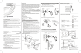
Hardware Hookup
Refer to the following hookup diagram and, aside from attaching power last,
complete the connections in any order. Refer to "Network Wiring" on page 11 when
making network connections.
NOTE: To prevent overheating, do not operate this product in an area that exceeds
the environmental temperature range listed in the table of leading specifications.
Consideration must be given if installed in a closed or multi-unit rack assembly since
the operating ambient temperature of the rack environment may be greater than the
room ambient. Contact with thermal insulating materials should be avoided on all
sides of the unit.
NOTE: The maximum continuous current from equipment under any external load
conditions shall not exceed a current limit that is suitable for the minimum wire
gauge used in interconnecting cables. The ratings on the connecting unit's supply
input should be considered to prevent overloading the wiring.
Hookup Connections for the CP2/CP2E
TO CONTROLLABLE
DEVICES
FROM DEVICE
OUTPUTS
- CONTACT CLOSURES
- SOLID STATE CLOSURES
TO
IRP2
OR
SERIAL
DEVICES
TO
CONTROLLABLE
DEVICES
TO PC
SERIAL
PORT
TO ANY
RS-232,
-422, OR
-485 DEVICE
TO ANY
CRESNET
NETWORK
DEVICE
CRESTRON,
ROCKLEIGH, NJ
07647
USA
24VDC
2.0A
COM C
COM B
COM A
OUTPUT
1 2 3 4
5 6 7 8
A B C D E F G H
S G S G S G S G
1 2 3 4 5 6 7 8 G
I/OINFRARED - SERIAL OUTPUT
G Z Y 24
24VDC 24W
NET COMPUTER
RELAY
LAN
S G S G S G S G
TO AC
POWER
PACK
(24VDC, 2A
OUTPUT)
10/100 BASE-T
ETHERNET
TO LAN
OR WEB
12 • 2-Series Integrated Control Processor: CP2/CP2E Operations Guide - DOC. 5980

Crestron CP2/CP2E 2-Series Integrated Control Processor
Optional Power Supply
The units can be powered through the NET network connector, or by an optional
AC power pack (purchased separately). If an external power supply is to be used,
Crestron recommends its CNPWS-75 External Power Supply or PW-2420RU
Universal Power Pack, or equivalent.
NOTE: Use care in wiring installations to avoid applying 24 VDC power to Cresnet
wiring from an AC power pack as well as from a system device that contains its own
power supply. Although this condition should not cause any damage, Crestron does
not recommend it. In those network configurations that require more power than can
be supplied by Crestron’s Power Control Unit alone, disconnect the +24 VDC
Cresnet wire from those devices that will be powered by an AC power pack.
Programming the CP2 and CP2E
SIMPL Windows is Crestron’s graphical, Windows-based development tool for
programming control systems. The SIMPL Windows interface provides two
workspaces: the Configuration Manager, for configuring the control system,
touchpanels, and controlled network devices; and Program Manager, for designing
the logic and functionality of the control system.
In addition, you can use Crestron’s powerful Viewport utility to accomplish multiple
system tasks, such as uploading the program to the control system and performing
diagnostic functions. Together with the Crestron Database, these tools provide you
with the essential components you need to program the CP2/CP2E. Crestron
software is available on CD-ROM, or can be downloaded from the Crestron website
(www.crestron.com
)—registration is required for downloading.
Following are the minimum software requirements for the PC:
• SIMPL Windows version 2.00.28, with Library Update 145
• Crestron Database version 15.6.2
• (Optional) VisionTools Pro-e software for designing touchpanel pages
• (Optional) Application Builder (also requires SIMPL+ Cross Compiler)
software for automatic residential and commercial programming
• (Optional) DEAL for Windows IR learning software version 2.07
CP2/CP2E Device Library Symbols
In Configuration Manager, drag the CP2 or CP2E from the Control Systems folder of
the Device Library to System Views. The CP2 and CP2E appear nearly identical,
except that the CP2E provides an additional slot for Ethernet devices, as shown
below.
System Views of the CP2 and CP2E
Operations Guide - DOC. 5980 2-Series Integrated Control Processor: CP2/CP2E• 13

2-Series Integrated Control Processor Crestron CP2/CP2E
Slot 1: C2Net-Device
The C2Net-Device slot enables the CP2 and CP2E to control up to 252 Cresnet
devices. Each Cresnet device is assigned a unique identifier called a Net ID, which is
a hexadecimal value ranging from 03 to FE.
To view the list of supported devices, expand the control system in the bottom pane
of System Views and double-click the C2Net-Device slot, or right-click and select
Add Item from the submenu. Supported devices include network control modules,
lighting modules and a variety of Crestron wired touchpanels.
To add a device to the system expand the C2 Net-Device slot and double-click the
desired Net ID, or right click and select Add Item from the submenu. Then select the
device you want to add. Alternatively, you can drag the device from the Cresnet
Modules folder onto the Net ID.
In Program Manager, the C2Net-Device symbol contains no signals; to program a
controlled Cresnet device, expand the C2Net-Device symbol in Program View. Then
drag the device to Detail View.
Slot 2: C2I-IR8
The CP2 and CP2E provide 8 output ports (A through H) that enable serial
communication in a variety of formats, including infrared and one-way RS-232. Of
course, different devices may require additional receiving equipment, cables,
adapters, etc.
To add an IR device to the system, drag the device driver from the Crestron or User
IR Database to a C2I-IR8 port.
To add an RS-232 device, drag the C2IR one-way serial driver from the Serial
Drivers folder to a C2I-IR8 port. Alternatively, you can double-click a C2I-IR8 port
and select the C2IR one-way serial driver (or right-click and select Add Item from
the submenu).
Next, double-click the serial driver to specify the communication settings that are
required by the device. These settings define the protocol that the controlled serial
device expects, and include the speed of data transmission (baud rate), error
checking (parity), and the number of data bits and stop bits. The exact protocol will
be described in the manufacturer's documentation.
NOTE: The C2IR serial driver, being one way, does not provide hardware or
software handshaking.
In Program Manager, the C2I-IR8 symbol contains no signals; to program an IR
device or serial driver, expand the C2I-IR8 card by clicking the plus sign in Program
View. Then drag the symbol to Detail View. (Alternatively, double-click the symbol.)
14 • 2-Series Integrated Control Processor: CP2/CP2E Operations Guide - DOC. 5980

Crestron CP2/CP2E 2-Series Integrated Control Processor
Slot 3: C2I-IO8
The CP2 and CP2E provide eight I/O ports called Versiports, each of which can
function as a digital input, a digital output, or an analog input. Each Versiport has a
corresponding pullup resistor.
In Program Manager, drag the C2I-IO8 symbol from Program View to Detail View.
The symbol contains the following signals, arranged here according to mode:
Signals
Digital output mode
• 8 digitals: <o1> through <o8>
Digital input mode
• 8 digitals: <i1> through <i8>
Analog input mode
• 8 analogs: <i1> through <i8>
• For each analog, one corresponding minimum change value:
<MinChange1> through <MinChange8>
All Versiport modes
• For each Versiport, one corresponding pullup resistor: <pu-disable1>
through <pu-disable8>
Defining a signal puts the signal into the corresponding mode. For example, defining
the analog input <i1> configures that Versiport as an analog input. A Versiport can
only operate in one mode. That is, if you define <o1> you should not also define
<i1>.
Description
Internal configuration of a Versiport
Digital Output Mode
When a Versiport is operating in digital output mode, the output pin will be shorted
to ground on the rising edge of the corresponding <o> signal (switch S1-B in the
Versiport diagram will be closed). When <o> goes low, the output pin is driven to a
value of +5V (switch S1-B is open).
Operations Guide - DOC. 5980 2-Series Integrated Control Processor: CP2/CP2E• 15

2-Series Integrated Control Processor Crestron CP2/CP2E
Driving the corresponding <pu-disable> signal high can modify this behavior. This is
not recommended, though, since it will cause the output pin to float when <o> goes
low.
Example 1 (recommended):
The <pu-disable1> signal is driven low or left undefined. When <o1> goes
low, Versiport 1 is at +5V. When <o1> goes high, Versiport 1 is shorted to
ground.
Example 2 (not recommended):
The <pu-disable1> signal is driven high. When <o1> goes low, Versiport
1 is floating. When <o1> goes high, Versiport 1 is shorted to ground.
Digital Input Mode
When a Versiport is operating in digital input mode, the corresponding <i> signal
will go high whenever the C2I-IO8 detects that the Versiport is shorted to ground
(threshold < +2.5V).
NOTE: Here, as with digital output mode, the corresponding pullup resistor should
be enabled. That is, <pu-disable> should be given the signal name 0 or left
undefined; otherwise the input will always read as logic low.
Example 3:
When Versiport 3 is shorted to ground, <i3> will go high. When Versiport 3
is not shorted to ground, <i3> will go low (so long as <pu-disable> equals
0 or is undefined).
Analog Input Mode
In analog input mode, the Versiport is typically tied to a resistive load (such as a
humidity sensor) or a voltage source (both can be represented by box "A" in the
Versiport diagram).
When a resistive load is tied to a Versiport, the corresponding pullup resistor must be
enabled (again, this means that <pu-disable> should be given the signal name 0 or
left undefined). This creates a voltage divider and provides a varying voltage level,
based on the current resistance of the sensor for the C2I-IO8 to read.
Example 4:
A resistive humidity sensor is tied to Versiport 1 (and <pu-disable1> is low
or undefined). <i1> will assume the corresponding analog value.
When a voltage source is tied to a Versiport, the corresponding pullup resistor should
be disabled (the only case where the default setting should be overridden). This
allows the C2I-IO8 to read the value of the voltage source directly.
Example 5:
A voltage source is tied to Versiport 1 and <pu-disable1> is given the
signal name 1. <i1> will assume the corresponding analog value (ranging
from 0 to 65535, or 0 to +10V on the input pin).
The C2I-IO8 does not propagate all changes in the analog values of its Versiports,
since this can lead to undesirable results if the input source is not clean or has jitter.
Rather, the <MinChange> signals should be used to specify a "minimum change"
value, such that the C2I-IO8 will not propagate the new value until it changes by
<MinChange>. (The default minimum change value is 2048.)
Example 6:
16 • 2-Series Integrated Control Processor: CP2/CP2E Operations Guide - DOC. 5980
/