Page is loading ...

© 2007 HeathCo LLC 598-1165-05
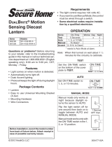
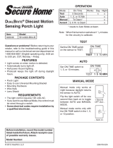
ON-TIME
TEST 1 5 10 MIN
Set ON-TIME switch to 1,
5, or 10 minutes.
ON-TIME
Set the ON-TIME switch
on the bottom of the cover
plate to TEST.
... back on.
1 Second
OFF then...
Manual mode only works at
night because daylight returns
the sensor to AUTO.
Flip the light switch off for one
second then back on to toggle
between AUTO and MANUAL
MODE.
Manual mode works only with
the ON-TIME switch in the 1,
5, or 10 position.
Note: When first turned on wait about 1
1
/
2
minutes for the circuitry to calibrate.
MANUAL MODE
AUTO
TEST 1 5 10 MIN
* resets to Auto Mode at dawn.
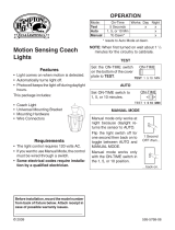
OPERATION
TEST
Motion Sensing
Coach Lights
Before installation, record the model number
from back of fixture below. Attach receipt in
case of possible warranty issues.
Mode: On-Time Works: Day Night
Test
5 Seconds x x
Auto
1, 5, or 10 Min x
Manual
To Dawn* x
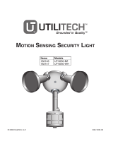
Items Models
008812 PF-4150-SC
066300 PF-4150-PB
066494 PF-4150-BK
066565 PF-4160-AB
066579 PF-4162-PB
066580 PF-4170-PB
Questions or problems? Before returning
to your retailer, refer to the troubleshooting
guide in this manual or call our technical ser-
vice department at 1-800-858-8501 (English
speaking only), 7:30 am to 4:30 pm, CST,
Monday – Friday.
Features
• Light comes on when motion is detected.
• Automatically turns light off.
• Photocell keeps the light off during daylight
hours.
Package Contents
• Lantern
• Easy to use Universal Mounting Bracket
• Mounting Hardware
• Wire Connectors
• Some Models Include an Optional Decora
-
tive Tail Assembly
Requirements
• The light control requires 120 volts AC.
• If you want to use Manual Mode, the control
must be wired through a switch.
• Some electrical codes require installa
-
tion by a qualified electrician.

2
598-1165-05
INSTALLATION
Estimated Installation Time: 30 minutes
Items needed for installation (not included):
• Phillips and flathead screwdrivers
• Pliers • Wire strippers/cutters
• Safety glasses • Light bulb
• Silicone caulk
For best performance, mount the fixture about
6 feet (1.8 m) above the ground.
1. Remove two nuts.
3. Tighten screws
finger tight.
2. Remove
Mounting Plate.
WARNING: Turn power off at circuit
breaker or fuse.
ON-TIME Switch at 1, 5,
or 10 minutes
Mode Switching Summary
Flip light switch
off for one second
then back on*
* If you get confused while switching modes,
turn the power off for one minute, then back
on. After the calibration time the control will
be in the AUTO mode.
MANUAL MODE
AUTO
TEST
This fixture comes with a universal mounting
bracket. It is pre-assembled on the fixture to
fit the majority of junction box applications.
However, if the slots on the mounting plate
do not line up with the junction box screw
holes:
1. Remove the fixture mounting screws from
the mounting plate. Note: Do not remove
the ground screw.
2. Attach ground wire “pigtail” to ground
screw on mounting plate (See
Recommended Grounding Method for
additional information).
3. Flip the mounting plate over.
4. Rotate the mounting plate so the wire path
is on the upper right. Note: The wire path
on the mounting plate must be located
as shown below to allow the wires on the
back of the fixture to pass through.
5. Reinstall the fixture mounting screws and
attach the mounting plate to the junction
box as shown.
Wire Path
4. Attach mounting plate to junction box.
Wire Path
Ground Screw
As Shipped Flipped and
Rotated
Wire Path
Fixture Screws
Ground Screw

3
598-1165-05
Black to black
White to white
Recommended Grounding Method
Use a green ground “pigtail” (not provided) and
twist one end together with the bare fixture wire
and the box ground wire. Secure with a wire
connector. Secure the other end of the “pigtail”
with the GND screw on the mounting plate.
WIRING
One Motion Light
❒ Twist the junction box wires and the
fixture wires together as shown below.
Secure with wire connectors. If you have
a metal junction box, you may not need
the green “pigtail”. If you are unsure about
the grounding method, consult your local
building code.
Two Motion Lights
Black
White
Green
or Bare
Light
Fixture
Black
White
Green
or Bare
Light
Fixture
Light
Fixture
CAUTION: DO NOT connect the RED
wire unless you want to control other
lights from the motion sensor.
Note: All wiring should be run in accordance
with the National Electrical Code through
conduit or another acceptable means.
Contact a qualified electrician if there is
any question as to the suitability of the
system.
Connect the fixture wires to the wires in the
junction box. Twist the wires together and
secure with wire connectors.

4
598-1165-05
OPTIONAL WIRING
This fixture is provided with a sensor rated for 500 Watts. Since the fixture is only rated 100
Watts, 400 Watts of additional lighting may be controlled by this sensor.
When determining what a fixture is rated for, do not simply look at the rating on the lamp in
the fixture. Look at the marking which specifies the maximum lamp wattage for which the
fixture is suitable.
Once you have selected the fixtures to be connected and determined their maximum ratings,
add these ratings up. For instance, if you have 3 fixtures rated 100 Watts, 150 Watts, and
75 Watts respectively, you have a total load of 325 Watts.
Wiring Diagram 1 – When wiring to control a standard light fixture: Strip the motion sensor’s
red wire and connect to the standard light’s black wire. Connect all white wires together.
Total fixture ratings must not exceed 500 Watts (4.1 A).
Wiring Diagram 2 – When wiring to control another motion sensing light fixture (Master /
Slave): Strip the red wire in both light fixtures. Connect the red wire of the controlling (master)
fixture to the red and black wires of the controlled (slave) fixture. Connect all white wires
together. Total fixture ratings must not exceed 500 Watts (4.1 A).
Wiring Diagram 1
Black
White
Green
or Bare
Light
Fixture
Light
Fixture
Wiring Diagram 2
(Standard)
Master Slave
It is also possible to wire two motion lights so that either fixture will turn on both lights at the
same time (dual master system). It is recommended that only people with plenty of electrical
experience attempt this configuration. Please call our customer service number (1-800-858-
8501 - English speaking only) before attempting this wiring. If the dual master wiring is not
done correctly, it can destroy both motion sensing fixtures and void your warranty.
Black
White
Green
or Bare
Light
Fixture
Light
Fixture
Red
Red

5
598-1165-05
❒ Caulk fixture mounting surface with
silicone weather sealant.
❒ Install one 100 Watt maximum light bulb.
❒ If so equipped, install the fixture top. Secure
with decorative screws.
❒ If you will not be installing the optional tail
assembly, install the decorative nut onto
the bottom of the fixture now.
Slide the fixture onto the
mounting screws and
tighten nuts.
Junction
Box
Optional Assembly
❒ If so equipped, you may install the decora-
tive tail as shown below.
1. Screw in
extension bar.
2. Add tail piece
and trim.
3. Install
decorative nut.
Bottom trim piece
has drain hole
Hex nut
4162 Top Assembly
Larger piece
on top
COMPLETE THE INSTALLATION
❒ Stuff the wires into the junction box. Make
sure the wires from the fixture go through
the wire path, and no wires get pinched.

6
598-1165-05
TESTING
❒ Turn on the circuit breaker and light
switch.
❒ Set the SENSITIVITY as needed. Too much
sensitivity may increase false triggering.
❒ Set the amount of TIME you want the light
to stay on after motion is detected. (1, 5,
or 10 minutes).
240°
Sensor Aiming
Adjustment Angle
❒ Walk through the coverage area noting
where you are when the lights turn on.
Move the sensor head left or right to
change the coverage area.
Note: Grasp the sensor
only as shown and turn
the entire sensor. Any
other method may
damage the sensor.
Do not force it past
the stops.
Least Sensitive Most Sensitive
30 ft.
(9.1m)
Maximum Range Maximum
Coverage Angle
The detector is less sensitive to motion di-
rectly towards it and more sensitive to across
motion.
Sensor
MotionMotion
6 ft.
(1.8 m)
Avoid aiming the control at:
• Pools of water or objects that change
temperature rapidly, such as heating vents
and air conditioners. These heat sources
could cause false triggering.
• Areas where pets or traffic may trigger
the control.
• Nearby large, light-colored objects
reflecting daylight may trigger the shut-off
feature. Do not point other lights at the
sensor.
Note: Sensor has a 1
1
/
2
minute warm up pe-
riod before it will detect motion. When
first turned on wait 1
1
/
2
minutes.
TEST 1 5 10 MIN
ON-TIME
LO - M - HI
SENSITIVITY
150°
❒ Set SENSITIVITY to mid position and
ON-TIME to TEST position.

7
598-1165-05
SPECIFICATIONS
Range . . . . . . . . . . Up to 30 ft. (9.1 m)
[varies with surrounding
temperature].
Sensing Angle . . . . Up to 150°
Electrical Load . . . . U p to 1 0 0 Wa t t
Maximum Tungsten
Incandescent
Sensor Capacity . . Up to 500 Watt (4.1
A.) Maximum Tungsten
Incandescent
Power Requirements .... 120 VAC, 60 Hz
Operating Modes . . TEST, AUTO, and
MANUAL MODE
Time Delay . . . . . . 1, 5, 10 minutes
HeathCo LLC reserves the right to discon-
tinue products and to change specifications
at any time without incurring any obligation
to incorporate new features in products pre-
viously sold.
TROUBLESHOOTING GUIDE
SYMPTOM
Light stays on
continuously.
Light flashes
on and off.
POSSIBLE CAUSE
1. The sensor is pointed toward
a heat source like an air vent,
dryer vent, or brightly-painted
heat-reflective surface. (Re-aim
sensor.)
2. Light control is in Manual Mode.
(Switch to Auto.)
3. Sensitivity is set too high.
(Reduce sensitivity.)
1. Heat being reflected from other
objects may be affecting the
sensor. (Re-aim sensor.)
2. Light control is in the Test
mode and war ming up
(flashing is normal under these
conditions).
POSSIBLE CAUSE
1. Light switch is turned off.
2. Bulb is loose or burned out.
3. Fuse is blown or circuit breaker
is turned off.
4. Daylight turn-off is in effect
(recheck after dark).
5. Incorrect circuit wiring, if this
is a new installation.
6. Re-aim the sensor to cover
desired area.
1. Light control may be installed
in a relatively dark location.
2. Light control is in Test. (Set
control switch to an ON-TIME
position.)
1. Light control may be sensing
small animals or automobile
traffic (re-aim sensor).
2. Sensitivity is set too high.
(Reduce sensitivity.)
SYMPTOM
Light will not
come on.
Light comes on
in daylight.
Light comes on
for no apparent
reason.

8
598-1165-05
THREE YEAR LIMITED WARRANTY
This is a “Limited Warranty” which gives you specific legal rights. You may also have other rights
which vary from state to state or province to province.
For a period of three years from the date of purchase, any malfunction caused by factory defective
parts or workmanship will be corrected at no charge to you.
Not Covered - Repair service, adjustment and calibration due to misuse, abuse or negligence,
light bulbs, batteries, and other expendable items are not covered by this warranty. Unauthorized
service or modification of the product or of any furnished component will void this warranty in its
entirety. This warranty does not include reimbursement for inconvenience, installation, setup time,
loss of use, unauthorized service, or return shipping charges.
This warranty covers only HeathCo LLC assembled products and is not extended to other equip-
ment and components that a customer uses in conjunction with our products.
THIS WARRANTY IS EXPRESSLY IN LIEU OF ALL OTHER WARRANTIES, EXPRESS OR
IMPLIED, INCLUDING ANY WARRANTY, REPRESENTATION OR CONDITION OF MERCHANT
ABILITY OR THAT THE PRODUCTS ARE FIT FOR ANY PARTICULAR PURPOSE OR USE,
AND SPECIFICALLY IN LIEU OF ALL SPECIAL, INDIRECT, INCIDENTAL, OR CONSEQUEN-
TIAL DAMAGES.
REPAIR OR REPLACEMENT SHALL BE THE SOLE REMEDY OF THE CUSTOMER AND
THERE SHALL BE NO LIABILITY ON THE PART OF HEATHCO LLC FOR ANY SPECIAL, IN-
DIRECT, INCIDENTAL, OR CONSEQUENTIAL DAMAGES, INCLUDING BUT NOT LIMITED TO
ANY LOSS OF BUSINESS OR PROFITS, WHETHER OR NOT FORESEEABLE. Some states
or provinces do not allow the exclusion or limitation of incidental or consequential damages, so
the above limitation or exclusion may not apply to you. Please keep your dated sales receipt, it
is required for all warranty requests.
TECHNICAL SERVICE
Please call 1-800-858-8501 (English speaking only) for assistance before returning
product to store.
If you experience a problem, follow this guide. You may also want to visit our Web site at:
www.hzsupport.com. If the problem persists, call* for assistance at 1-800-858-8501 (English
speaking only), 7:30 AM to 4:30 PM CST (M-F). You may also write* to:
HeathCo LLC
P.O. Box 90004, Bowling Green, KY 42102-9004
ATTN: Technical Service
* If contacting Technical Service, please have the following information available: Model
Number, Date of Purchase, and Place of Purchase.
No Service Parts Available for this Product
/