Page is loading ...

PowerFlex 700 Adustable Frequency
AC Drive
Technical Data

PowerFlex 700 Technical Data
2 20B-TD001F-EN-P
Product Overview
The PowerFlex 700 AC drive offers outstanding performance in an easy-to-use drive
that you have come to expect from Rockwell Automation. This world-class
performance comes in a small and competitively priced package. The PowerFlex 700
AC drive is designed to control three-phase induction motors in applications with
requirements ranging from the simplest speed control to the most demanding torque
control. The drive has volts per hertz, sensorless vector and vector control. Vector
control includes Allen-Bradley’s patented Force™ Technology which provides
world class motor control.
Table of Contents
Description . . . . . . . . . . . . . . . . . . . . . . . . . . . . . . . . . . . . . . . . . Page
Standard Drives Program . . . . . . . . . . . . . . . . . . . . . . . . . . . . . . . . . .3
Catalog Number Explanation . . . . . . . . . . . . . . . . . . . . . . . . . . . . . . .5
Factory Installed Options . . . . . . . . . . . . . . . . . . . . . . . . . . . . . . . . . .7
User Installed Options. . . . . . . . . . . . . . . . . . . . . . . . . . . . . . . . . . . . .8
Installation Considerations . . . . . . . . . . . . . . . . . . . . . . . . . . . . . . . .17
Cable Recommendations. . . . . . . . . . . . . . . . . . . . . . . . . . . . . . . . . .31
Power Ratings and Branch Circuit Protection. . . . . . . . . . . . . . . . . .32
Maximum Motor Cable Lengths. . . . . . . . . . . . . . . . . . . . . . . . . . . .40
Mounting . . . . . . . . . . . . . . . . . . . . . . . . . . . . . . . . . . . . . . . . . . . . . .46
PowerFlex 700 Frames . . . . . . . . . . . . . . . . . . . . . . . . . . . . . . . . . . .47
Approximate Dimensions . . . . . . . . . . . . . . . . . . . . . . . . . . . . . . . . .48
PowerFlex 700 Packaged Drives. . . . . . . . . . . . . . . . . . . . . . . . . . . .71
Specifications . . . . . . . . . . . . . . . . . . . . . . . . . . . . . . . . . . . . . . . . . .72
Derating Guidelines. . . . . . . . . . . . . . . . . . . . . . . . . . . . . . . . . . . . . .75
Reference Materials
For additional PowerFlex 700 data and general drive information, refer to the following publications:
For other information, contact Allen-Bradley Drives Technical Support:
Title Publication Available Online at…
PowerFlex 700 Vector Control User Manual 20B-UM002… www.rockwellautomation.com
/literature
PowerFlex 700 Installation Instructions, Frames 0…6 20B-IN019…
PowerFlex 700 Installation Instructions, Frames 7…10 20B-IN014…
PowerFlex Reference Manual PFLEX-RM004…
Wiring and Grounding Guidelines for PWM AC Drives DRIVES-IN001…
Preventive Maintenance of Industrial Control and Drive System Equipment DRIVES-TD001…
Safety Guidelines for the Application, Installation and Maintenance of Solid State Control SGI-1.1
Title Online at
…
Allen-Bradley Drives Technical Support www.ab.com/support/abdrives

PowerFlex 700 Technical Data
20B-TD001F-EN-P 3
Standard Drives Program
Flexible Packaging and Mounting
• IP20, NEMA/UL Type 1 – For conventional mounting inside or outside a control cabinet. Conduit plate is removable
for easy installation and replacement without disturbing conduit.
• IP54, NEMA/UL Type 12 – Stand-alone, wall mount drives are available for dust tight applications with power ratings
from 75 to 200 Hp (Frames 5 & 6).
• IP54, NEMA/UL Type 12 – Flange mount drives with an IP00, NEMA/UL Type Open front. These can be installed in
a user supplied cabinet to meet IP54, NEMA/UL Type 12. This allows the majority of heat to be exhausted out the back
of the cabinet while keeping the cabinet protected. Power ratings range from 75 to 700 Hp (Frames 5…10).
• Zero Stacking™ – Frame 0…6 drives can be mounted next to each other with no reduction of surrounding air
temperature rating (50
°C). This unique bookshelf design also allows access to one drive without disturbing another.
Space Saving Hardware Features
• Integral EMC Filtering plus built-in DC bus choke common mode cores and common mode capacitors provides a
compact, all-in-one package solution for meeting EMC requirements, including CE in Europe. Frames 0…6 only
(Frames 7…10 meet CE when installed per recommendations).
• Internal Communications allow the user to integrate the drive into the manufacturing process. Status indicators for all
internal communication options are visible on the cover for easy setup and monitoring of drive communications. Users
can easily manage information from shop floor to top floor and seamlessly integrate their complete system as they
control, configure and collect data.
• Integral Dynamic Brake Transistor delivers a cost effective means of switching regenerative energy without costly
external chopper circuits. These internal transistors are available in power ratings from 0.5 to 200 Hp.
• Internal Dynamic Brake Resistor (up to 25 Hp) requires no extra panel space, and supplies a large amount of braking
torque for short periods.
Easy to Use Human Interface Tools
The PowerFlex 7-Class AC drives provide common Human Interface tools that are familiar and easy to use. These include
the LCD Human Interface modules and PC-based configuration tools.
• LCD Human Interface modules provide:
- Large and easy to read 7 line x 21 character backlit display
- Variety of languages (English, French, German, Italian, Spanish, Portuguese, Dutch)
- Alternate function keys for shortcuts to common tasks
- “Calculator-like” number pad for fast and easy data entry (Full Numeric version only)
- Control keys for local start, stop, speed, and direction
- Remote versions for panel mount application
• PC-based Configuration tools include:
- DriveExplorer™ and DriveExplorer Lite. Simple and flexible “On-line” tools for monitoring and configuring while
connected to a drive.
- DriveTools™ SP. A suite of software tools which provide an intuitive means for programming, troubleshooting and
maintaining Allen-Bradley AC & DC drives.
• For simplified AC drive start-up and reduced development time, we’ve integrated Allen-Bradley PowerFlex drive
configuration with RSLogix5000® software. This single-software approach simplifies parameter and tag programming
while still allowing stand-alone drive software tool use on the factory floor.

PowerFlex 700 Technical Data
4 20B-TD001F-EN-P
Outstanding Control and Performance
Multiple motor control algorithms allow performance matched to the
application need:
• Volts/Hertz for simple Fan and Pump applications.
• Sensorless Vector for high torque production over a wide speed range.
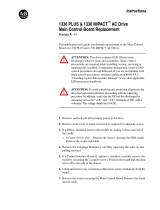
• Vector for outstanding torque regulation and excellent low speed/zero
speed performance (w/Vector Control cassette).
The PowerFlex 700 drive's Vector Control uses Allen-Bradley's patented
Force™ Technology which provides excellent low-speed performance -
whether it is operated with or without feedback. While this industry-leading
control provides the highest level of drive performance, it is as easy to use as
any general purpose drive available.
Drives Features
• Fast-acting Current Limit and Bus Voltage Regulation result in maximum accel/decel without tripping.
• High speed analog inputs improve drive response to torque or speed commands.
• Programming flexibility allows parameters to be linked within the drive.
• Flying Start delivers smooth and instantaneous connection into rotating loads, regardless of commanded direction,
without the need for any speed feedback.
• Integral Process PI Control can eliminate the need for a separate process loop controller.
• Inertia Ride-Through offers tripless operation during a prolonged power outage by using the rotating energy stored in
high inertia, low-friction loads.
• Position Indexer/Speed Profiler uses a 16 step indexer to provide point-to-point positioning or velocity profiling
based on encoder counts, digital inputs, parameter levels or time.
• TorqProve™ assures control of the load when transferring control between the drive and a mechanical brake.
• Speed Regulation - Open Loop or Closed Loop
- Slip Compensation delivers a minimum 0.5% speed regulation without feedback hardware.
- Droop allows drives to load share without fighting each other.
- Encoder Feedback provides up to 0.001% speed regulation for the tightest application requirements.
• Torque Regulation - Open Loop or Closed Loop
- Open Loop torque regulation provides ±5% regulation.
- Encoder Feedback provides ±2% regulation and the ability to hold full load at zero speed.
Unsurpassed Capability in Network Communications
PowerFlex drives are fully compatible with the wide variety of Allen-Bradley DPI™ communication adapters, offering
the following benefits:
BACnet®
Bluetooth®
ControlNet™
DeviceNet™
EtherNet/IP™
Interbus™
LonWorks™
Modbus RTU
PROFIBUS™
Remote I/O
RS485 DF1
USB
Description
✔✔✔ (Unconnected Messaging) permits other network devices (e.g. PanelView™) to communicate directly to a drive without routing the commu-
nication through the network scanner.
✔✔✔✔✔ ✔✔Adapter Routing - Plug PC into one drive and talk to all other Allen-Bradley drives on same network, without being routed through network
scanner.
✔✔✔✔✔✔✔✔✔✔✔✔Access to 100% of all parameters over the network.
✔✔✔ ✔ AutoBaud capability makes initial connections less problematic.
✔ Change of State significantly reduces network traffic by configuring control messages to be sent only upon customer defined states. Very
flexible configuration for each node (Example: “reference must change by more than 5%”).
✔✔ Peer Control provides master-slave type control between drives, where one or more slave drives (consumers) can run based on the status of
a master drive (producer), which can also significantly reduce network traffic.
✔ ADR (Automatic Device Replacement) saves significant time and effort when replacing a drive, by allowing the scanner to be configured to
automatically detect a new drive and download the required parameter settings.
✔✔✔✔✔✔✔✔✔✔✔✔Flexible Fault Configuration - Adapters can be programmed to take fault based actions as ramp to stop, coast-to-stop and hold last state,
as well as send user configurable logic control and speed reference values. In addition, different actions can be taken based on whether the
network experienced a serious problem (broken cable etc.) versus network idle condition (PLC set to “Program”).
0.0
0.5
1.0
1.5
2.0
2.5
3.0
-2 0 2 4 6 8 10 12
Frequency (HZ)
Closed Loop Performance
Open Loop Performance
Torque (Per-Unit)
02 4 681012
0.0
0.5
1.0
1.5
2.0
2.5
3.0
Frequency (HZ)
Torque (Per-Unit)

PowerFlex 700 Technical Data
20B-TD001F-EN-P 5
Catalog Number Explanation
Position
1-3 4 5-7 8 9 10 11 12 13 14 15 16 17-18 19-20
20B D 2P1 A 3 A Y N A R C 0 ADNN
abcdefghijklmn
a
Drive
Code Type
20B PowerFlex 700
b
Voltage Rating
Code Voltage Ph. Prechg. Frames
B 240V AC 3 - 0…6
C 400V AC 3 - 0…10
D 480V AC 3 - 0…10
E 600V AC 3 - 0…6
F 690V AC 3 - 5…6
H 540V DC - N 5…6, 10
J 650V DC - N 5…6, 10
N 325V DC - Y 5…6
P 540V DC - Y 5…9
R 650V DC - Y 5…9
T 810V DC - Y 5…6
W 932V DC - Y 5…6
c1
ND Rating
208/240V, 60 Hz Input
Code
208V
Amps
240V
Amps
Hp Frame
2P2 2.5 2.2 0.5 0
4P2 4.8 4.2 1.0 0
6P8 7.8 6.8 2.0 1
9P6 11 9.6 3.0 1
015 17.5 15.3 5.0 1
022 25.3 22 7.5 1
028 32.2 28 10 2
042 48.3 42 15 3
052 56 52 20 3
070 78.2 70 25 4
080 92 80 30 4
104 120 104 40 5
130 130 130 50 5
154 177 154 60 6
192 221 192 75 6
260 260 260 100 6
c2
ND Rating
400V, 50 Hz Input
Code Amps kW Frame
1P3 1.3 0.37 0
2P1 2.1 0.75 0
3P5 3.5 1.5 0
5P0 5.0 2.2 0
8P7 8.7 4.0 0
011 11.5 5.5 0
015 15.4 7.5 1
022 22 11 1
030 30 15 2
037 37 18.5 2
043 43 22 3
056 56 30 3
072 72 37 3
085 85 45 4
105 105 55 5
125 125 55 5
140 140 75 5
170 170 90 6
205 205 110 6
260 260 132 6
292 292 160 7
325 325 180 7
365 365 200 8
415 415 240 8
481 481 280 8
535 535 300 8
600 600 350 8
730 730 400 9
875 875 500 10
c3
ND Rating
480V, 60 Hz Input
Code Amps Hp Frame
1P1 1.1 0.5 0
2P1 2.1 1.0 0
3P4 3.4 2.0 0
5P0 5.0 3.0 0
8P0 8.0 5.0 0
0
011 11 7.5
014 14 10 1
022 22 15 1
027 27 20 2
034 34 25 2
040 40 30 3
052 52 40 3
065 65 50 3
077 77 60 4
096 96 75 5
125 125 100 5
156 156 125 6
180 180 150 6
248 248 200 6
292 292 250 7
325 325 250 7
365 365 300 8
415 415 350 8
481 481 400 8
535 535 450 8
600 600 500 8
730 730 600 9
875 875 700 10

PowerFlex 700 Technical Data
6 20B-TD001F-EN-P
c4
ND Rating
600V, 60 Hz Input
Code Amps Hp Frame
1P7 1.7 1.0 0
2P7 2.7 2.0 0
3P9 3.9 3.0 0
6P1 6.1 5.0 0
9P0 9.0 7.5 0
011 11 10 1
017 17 15 1
022 22 20 2
027 27 25 2
032 32 30 3
041 41 40 3
052 52 50 3
062 62 60 4
077 77 75 5
099 99 100 5
125 125 125 6
144 144 150 6
c5
ND Rating
690V, 50 Hz Input
Code Amps kW Frame
052 52 45 5
060 60 55 5
082 82 75 5
098 98 90 6
119 119 110 6
142 142 132 6
d
Enclosure
Code Enclosure
A IP20, NEMA/UL Type 1
F
Open/Flange Mount
Front: IP00, NEMA/UL Type Open
Back/Heatsink: IP54, NEMA Type 12
N §
Open/Flange Mount
Front: IP00, NEMA/UL Type Open
Back/Heatsink: IP54, NEMA 12
G
Stand-Alone/Wall Mount
IP54, NEMA/UL Type 12
J
IP00, NEMA/UL Type Open with
Conformal Coat
M
IP20, NEMA/UL Type 1 with Conformal
Coat
U
Roll-In
Front: IP00, NEMA/UL Type Open
Back/Heatsink: IP54, NEMA 12
Frames 8 & 9 Only
V
Roll-In with Conformal Coat
Front: IP00, NEMA/UL Type Open
Back/Heatsink: IP54, NEMA 12
Frames 8 & 9 Only
Only available for Frame 5 & Frame 6 drives,
400…690V.
§ Only available for Frames 7…10.
Only available with Vector Control option.
e
HIM
Code Operator Interface
0 Blank Cover
3 Full Numeric LCD
5 Prog. Only LCD
J
Remote (Panel Mount), IP66, NEMA/UL
Type 12 Full Numeric LCD HIM
K
Remote (Panel Mount), IP66, NEMA/UL
Type 12 Prog. Only LCD HIM
Available with Frames 5…6 Stand-Alone IP54
drives (Enclosure Code "G").
f
Documentation
Code Type
A Manual
N No Manual
Q
No Shipping Package
(Internal Use Only)
g
Brake
Code
w/Brake IGBT
YYes
NNo
Brake IGBT is standard on Frames 0-3,
optional on Frames 4-6 and not available on
Frames 7…10.
h
Internal Braking Resistor
Code w/Resistor
Y
Yes
NNo
Not available for Frame 3 drives or larger.
i
Emission
Code CE Filter
‡ CM Choke
A Yes Yes
B ♠
Yes No
NNoNo
‡ Note: 600V class drives below 77 Amps
(Frames 0-4) are declared to meet the Low
Voltage Directive. It is the responsibility of the
user to determine compliance to the EMC
directive. Frames 7…10, 400/480V AC drives
(Voltage Rating codes "C" and "D") meet CE
certification requirements when installed per
recommendations.
Refer to Internal EMC Filter for details on
selecting this option for each frame size.
♠ Only available for 208…240V Frame 0-3 drives.
j
Comm Slot
Code Network Type
B BACnet MS/TP
C ControlNet (Coax)
D DeviceNet
E EtherNet/IP
R Remote I/O
S RS485 DF1
NNone
k
Control & I/O
Code Control I/O Volts
A Standard 24V DC/AC
B Standard 115V AC
C
Vector
♣
24V DC
D
Vector
♣
115V AC
N Standard None
♣ Vector Control Option utilizes DPI Only. Frame
7…10 drives only accept Vector Control.
l
Feedback
Code Type
0None
1 Encoder, 12V/5V
m
Future Use
n
Special Firmware (Frames 0…6 Only)
Code Type
AD
60 Hz Maximum
AE
Cascading Fan/Pump Control
AX
82 Hz Maximum
BA
Pump Off (for pump jack)
Must be used with Vector Control option C or
D (Position k). Positions m-n are only required
when custom firmware is supplied.

PowerFlex 700 Technical Data
20B-TD001F-EN-P 7
Factory Installed Options
Conformal Coat (Position d = M) ‡
Description Frame
Conformal Coat
Printed circuit boards are coated with HumiSeal 1B73
acrylic coating to provide improved resistance to dust and
moisture. Consult factory for additional details.
0…10
‡ Only available with Vector Control option.
Human Interface and Wireless Interface Modules (Pos. e)
Cat. Code: 0
No HIM (Blank Plate)
IP20, NEMA/UL Type 1
Cat. Code: 3
LCD Display, Full Numeric
Keypad
IP20, NEMA/UL Type 1
Cat. Code: J
Remote (Panel Mount) LCD
Display, Full Numeric Keypad
IP66, NEMA/UL Type 4x/12
Cat. Code: K
Remote (Panel Mount) LCD
Display, Programmer Only
IP66, NEMA/UL Type 4x/12
Documentation
Description
Cat. Code
(Position f)
Manual
A
No Manual
N
Internal Brake IGBT
Drive Input Voltage Brake IGBT Frame
Cat. Code
(Position g)
208…480V AC Standard 0…3
Y
208…480V AC Optional 4
Y
208…690V AC Optional 5
Y
208…690V AC Optional 6
Y
The Internal Brake IGBT option cannot be field installed.
Internal Dynamic Brake Resistors
These resistors have a limited duty cycle. Refer to the PowerFlex
Dynamic Braking Selection Guide to determine if an internal
resistor will be sufficient. An external resistor may be required.
Drive Input
Voltage Frame
Brake Resistance
Cat. Code
Ω
(Position h)
208…240V AC
062
Y
1 (2…5 Hp) 62
Y
1 (7.5 Hp) 22
Y
222
Y
380…600V AC
0115
Y
1115
Y
380…480V AC 2 68
Y
Internal EMC Filter and Common Mode Choke
Drive Input
Voltage Frame CE Filter
Common
Mode Choke
Cat. Code
(Position i)
208…240V AC 3
§ w/Filter with Choke A
208…240V AC 0…3 w/Filter No Choke
B
208…240V AC 4…6 w/Filter with Choke
A
380…480V AC 0…6 w/Filter with Choke
A
380…480V AC 7…10
No Filter
No Choke N
600…690V AC 0…6
w/Filter
with Choke A
Note: 600V class drives below 77 Amps (Frames 0-4) are declared to meet
the Low Voltage Directive. It is the responsibility of the user to determine
compliance to the EMC directive.
§ Applies only to the 52 Amp drive.
Frames 7…10, 400/480V AC drives meet CE certification requirements
when installed per recommendations (refer to the User Manual, publication
20B-UM002).
Internal Communication Adapters
Description
Cat. Code
(Position j)
ControlNet™ Communication Adapter (Coax)
C
DeviceNet™ Communication Adapter
D
EtherNet/IP™ Communication Adapter
E
Control and I/O Options
Control
Cat. Code
(Position k)
Vector Control (Series B) - 24V DC
‡♠
C
Vector Control (Series B) - 115V AC
‡♠
D
‡ Vector Control option utilizes DPI Only.
♠ Frames 7…10 MUST select a Vector Control option.
Feedback Options (Vector Control Only)
Description
Cat. Code
(Position l)
No Encoder
0
12V/5V Encoder
ä 1
Encoder option can also be used as a pulse input.
Special Firmware
Description
Cat. Code
(Position m…n)
60 Hz Maximum
NNAD
Cascading Fan/Pump Control
NNAE
82 Hz Maximum
NNAX
Pump Off (for Pump Jack)
NNBA
Must be used with Vector Control option C or D (position k), Frames 0…6
onl
y
.

PowerFlex 700 Technical Data
8 20B-TD001F-EN-P
User Installed Options
Human Interface and Wireless Interface Modules
No HIM (Blank Plate)
20-HIM-A0
LCD Display, Full
Numeric Keypad
20-HIM-A3
LCD Display,
Programmer Only
20-HIM-A5
Wireless Interface
Module
20-WIM-N1
Remote (Panel Mount)
LCD Display, Full
Numeric Keypad
20-HIM-C3S
Remote (Panel Mount)
LCD Display,
Programmer Only
20-HIM-C5S
Remote (Panel Mount)
Wireless Interface
Module
20-WIM-N4S
Human Interface Module Accessories
Description Cat. No.
Bezel Kit for LCD HIMs, NEMA/UL Type 1
‡ 20-HIM-B1
PowerFlex HIM Interface Cable, 1 m (39 in)
♣
20-HIM-H10
Cable Kit (Male-Female)
ä
0.33 Meters (1.1 Feet) 1202-H03
1 Meter (3.3 Feet)
1202-H10
3 Meter (9.8 Feet)
1202-H30
9 Meter (29.5 Feet)
1202-H90
DPI/SCANport™ One to Two Port Splitter Cable
1203-S03
‡ Includes a 1202-C30 interface cable (3 meters) for connection to drive.
♣ Required only when HIM is used as handheld or remote.
Required in addition to 20-HIM-H10 for distances up to a total maximum
of 10 Meters (32.8 Feet).
Encoder Option Kit (Vector Control Only)
Description Cat. No.
12V/5V Encoder
20B-ENC-1
12V/5V Encoder with Conformal Coat
20B-ENC-1-MX3
I/O Option Kit (Standard Control Only)
Description Cat. No.
24V DC/AC 20-DA1-A0
115V AC
20-DA1-B0
Terminal Block Replacement Kit
Description Cat. No.
Removable I/O Terminal Block
SK-G9-TB1-S1
Removable Encoder Terminal Block
SK-G9-TB1-ENC1
Control Cassette Option Kits
Control with I/O Cat. No.
Standard Control (Open Loop) - No I/O
20B-STD-N
Standard Control (Open Loop) - 24V DC/AC
20B-STD-A0
Standard Control (Open Loop) - 115V AC
20B-STD-B0
Vector Control (Series B) - 24V DC
20B-VECTB-C0
Vector Control (Series B) - 24V DC with:
60 Hz Maximum 20B-VECT-C0AD
82 Hz Maximum
20B-VECTB-C0AX
Cascading Fan/Pump Control
20B-VECT-C0AE
Pump Off (for Pump Jack)
20B-VECTB-C0BA
Vector Control (Series B) - 24V DC, Conformal Coat
20B-VECTB-C0-
MX3
Vector Control (Series B) - 115V AC
20B-VECTB-D0
Vector Control (Series B) - 115V AC with:
60 Hz Maximum 20B-VECT-D0AD
82 Hz Maximum
20B-VECTB-D0AX
Cascading Fan/Pump Control
20B-VECT-D0AE
Pump Off (for Pump Jack)
20B-VECT-D0BA
Vector Control (Series B) - 115V AC, Conformal Coat
20B-VECTB-D0-
MX3
Vector Control option utilizes DPI Only.
Description
Handheld/Local
(Drive Mount)
Remote (Panel
Mount) IP66,
NEMA/UL Type
4x/12
Cat. No. Cat. No.
No HIM (Blank Plate)
20-HIM-A0 –
LCD Display, Full Numeric Keypad
20-HIM-A3 20-HIM-C3S ‡
LCD Display, Programmer Only 20-HIM-A5 20-HIM-C5S ‡
Wireless Interface Module 20-WIM-N1 20-WIM-N4S
For indoor use only.
‡ Includes a 1202-C30 interface cable (3 meters) for connection to drive.

PowerFlex 700 Technical Data
20B-TD001F-EN-P 9
Internal Dynamic Brake Resistor Kits
These resistors have a limited duty cycle. Refer to the PowerFlex
Dynamic Braking Selection Guide to determine if an internal
resistor will be sufficient for your application. An external resistor
may be required.
Drive Input
Voltage
Brake Resistance
Frame
Cat. No.
Ω
208…240V AC
62 0
20BB-DB1-0
62 1 (2…5 Hp)
20BB-DB1-1
22 1 (7.5 Hp)
20BB-DB2-1
22 2
20BB-DB1-2
380…600V AC
115 0
20BD-DB1-0
115 1
20BD-DB1-1
380…480V AC 68 2
20BD-DB1-2
§ Discount Schedule C2.
Dynamic Brake, Chopper Only Kits
Description Rating Cat. No.
200…240V AC
18A 1336-WA018
70A 1336-WA070
115A 1336-WA115
380…480V AC
9A 1336-WB009
35A 1336-WB035
110A 1336-WB110
500…600V AC
9A 1336-WC009
35A 1336-WC035
85A 1336-WC085
Terminators
Description
Cat. No.
for use with 3.7 kW (5 Hp) & below drives
1204-TFA1
for use with 1.5 kW (2 Hp) & up drives
1204-TFB2
See Appendix A of publication DRIVES-IN001 for selection information.
PC Programming Software
Description
DriveTools™ SP Software
See publication 9303-PL002… for
ordering/pricing information.
DriveExplorer™ Software (Lite/Full)
Set-up wizards are available for use with DriveTools SP and DriveExplorer
(Lite/Full) only.
DriveExplorer Lite is available for free download at:
http://www.ab.com/drives/driveexplorer/free_download.html.
Reflected Wave Reduction Modules w/CM Choke
Description
Cat. No.
17A with Common Mode Choke
1204-RWC-17-A
See Appendix A of publication DRIVES-IN001 for selection information.
Communication Option Kits
Description Cat. No.
BACnet
®
MS/TP RS485 Communication Adapter 20-COMM-B
ControlNet™ Communication Adapter (Coax)
20-COMM-C
ControlNet™ Communication Adapter (Coax)
Conformal Coat
20-COMM-C-MX3
DeviceNet™ Communication Adapter
20-COMM-D
DeviceNet™ Communication Adapter Conformal Coat
20-COMM-D-MX3
EtherNet/IP™ Communication Adapter
20-COMM-E
EtherNet/IP™ Communication Adapter Conformal Coat
20-COMM-E-MX3
HVAC Communication Adapter
20-COMM-H
Interbus™ Communication Adapter
20-COMM-I
CANopen
®
Communication Adapter 20-COMM-K
LonWorks
®
Communication Adapter♠
20-COMM-L
Modbus/TCP Communication Adapter
20-COMM-M
PROFIBUS™ DP Communication Adapter
20-COMM-P
ControlNet™ Communication Adapter (Fiber)
20-COMM-Q
Remote I/O Communication Adapter
20-COMM-R
Remote I/O Communication Adapter Conformal Coat
20-COMM-R-MX3
RS485 DF1 Communication Adapter
20-COMM-S
RS485 DF1 Communication Adapter Conformal Coat
20-COMM-S-MX3
External Communications Kit Power Supply
20-XCOMM-AC-
PS1
DPI External Communications Kit
20-XCOMM-DC-
BASE
External DPI I/O Option Board
‡
20-XCOMM-IO-
OPT1
Compact I/O Module (3 Channel)
1769-SM1
Serial Null Modem Adapter
1203-SNM
Smart Self-powered Serial Converter (RS232) includes
1203-SFC and 1202-C10 Cables
1203-SSS
Universal Serial Bus™ (USB) Converter includes 2m
USB, 20-HIM-H10 & 22-HIM-H10 Cables
1203-USB
‡ For use only with DPI External Communications Kits 20-XCOMM-DC-
BASE.
Only Modbus RTU can be used with Vector Control.
♠ Can only be used with Standard Control.
Reflected Wave Reduction Modules
Voltage Drive Cat. No. ND Hp Cat. No.
480V AC
20BD8P0 5.0
1321-RWR8-DP
20BD011 7.5
1321-RWR12-DP
20BD014 10.0
1321-RWR18-DP
20BD022 15.0
1321-RWR25-DP
20BD027 20.0
1321-RWR35-DP
20BD034 25.0
1321-RWR35-DP
20BD040 30.0
1321-RWR45-DP
20BD052 40.0
1321-RWR55-DP
20BD065 50.0
1321-RWR80-DP
20BD077 60.0
1321-RWR80-DP
20BD096 75.0
1321-RWR100-DP
20BD125 100.0
1321-RWR130-DP
20BD156 125.0
1321-RWR160-DP
20BD180 150.0
1321-RWR200-DP
20BD248 200.0
1321-RWR250-DP
20BD292 250.0
1321-RWR320-DP
600V AC
20BE6P1 5.0
1321-RWR8-EP
20BE9P0 7.5
1321-RWR12-EP
20BE011 10.0
1321-RWR12-EP
20BE017 15.0
1321-RWR18-EP
20BE022 20.0
1321-RWR25-EP
20BE027 25.0
1321-RWR35-EP
20BE032 30.0
1321-RWR35-EP
20BE041 40.0
1321-RWR45-EP
20BE052 50.0
1321-RWR55-EP
20BE062 60.0
1321-RWR80-EP
20BE077 75.0
1321-RWR80-EP
20BE099 100.0
1321-RWR100-EP
20BE125 125.0
1321-RWR130-EP
20BE144 150.0
1321-RWR160-EP

PowerFlex 700 Technical Data
10 20B-TD001F-EN-P
Isolation Transformers
For installations that have specific types of AC supply configurations or require drive protection due to AC line
disturbances, isolation transformers are available.
Motor Rating
kW (Hp)
IP32 (NEMA/UL Type 3R)
240V, 60 Hz, Three-Phase,
240V Primary & 240V Secondary
460V, 60 Hz, Three-Phase,
460V Primary & 460V Secondary
575V, 60 Hz, Three-Phase,
575V Primary & 575V Secondary
Cat. No. Cat. No. Cat. No.
0.25 (0.33) 1321-3TW005-AA 1321-3TW005-BB –
0.37 (0.5) 1321-3TW005-AA 1321-3TW005-BB –
0.55 (0.75) 1321-3TW005-AA 1321-3TW005-BB –
0.75 (1.0) 1321-3TW005-AA 1321-3TW005-BB 1321-3TW005-CC
1.1 (1.5) 1321-3TW005-AA 1321-3TW005-BB –
1.5 (2.0) 1321-3TW005-AA 1321-3TW005-BB 1321-3TW005-CC
2.2 (3.0) 1321-3TW005-AA 1321-3TW005-BB 1321-3TW005-CC
4.0 (5.0) 1321-3TW007-AA 1321-3TW007-BB 1321-3TW007-CC
5.5 (7.5) 1321-3TW011-AA 1321-3TW011-BB 1321-3TW011-CC
7.5 (10) 1321-3TW014-AA 1321-3TW014-BB 1321-3TW014-CC
11 (15) 1321-3TW020-AA 1321-3TW020-BB 1321-3TW020-CC
15 (20) 1321-3TW027-AA 1321-3TW027-BB 1321-3TW027-CC
18.5 (25) 1321-3TW034-AA 1321-3TW034-BB 1321-3TW034-CC
22 (30) 1321-3TW040-AA 1321-3TW040-BB 1321-3TW040-CC
30 (40) 1321-3TW051-AA 1321-3TW051-BB 1321-3TW051-CC
37 (50) 1321-3TH063-AA 1321-3TH063-BB 1321-3TH063-CC
45 (60) 1321-3TH075-AA 1321-3TH075-BB 1321-3TH075-CC
55 (75) 1321-3TH093-AA 1321-3TH093-BB 1321-3TH093-CC
75 (100) – 1321-3TH118-BB 1321-3TH118-CC
90 (125) – 1321-3TH145-BB 1321-3TH145-CC
110 (150) –
1321-3TH175-BB 1321-3TH175-CC
149 (200) – 1321-3TH220-BB 1321-3TH220-CC
187 (250) – 1321-3TH275-BB 1321-3TH275-CC
224 (300) – 1321-3TH330-BB 1321-3TH330-CC
261 (350) – 1321-3TH440-BB 1321-3TH440-CC
298 (400) – 1321-3TH440-BB 1321-3TH440-CC
336 (450) – 1321-3TH550-BB 1321-3TH550-CC
373 (500) – 1321-3TH550-BB 1321-3TH550-CC
448 (600) – 1321-3TH660-BB 1321-3TH660-CC
485 (650) – – 1321-3TH770-CC
522 (700) – 1321-3TH770-BB 1321-3TH770-CC

PowerFlex 700 Technical Data
20B-TD001F-EN-P 11
Input/Output Line Reactors
For impedance matching, protection from AC line disturbances or motor protection, reactors are available for both the
input and output sides of the drive.
240V, 60 Hz, Three-Phase, 3% Impedance
Drive Cat. No. Duty Hp
Input Line Reactor
(1)
(1)
Input line reactors were sized based on the NEC fundamental motor amps. Output line reactors were sized based on the VFD rated output currents.
Output Line Reactor
(1)
IP00 (Open Style) IP11 (NEMA/UL Type 1) IP00 (Open Style) IP11 (NEMA/UL Type 1)
Cat. No. Cat. No. Cat. No. Cat. No.
20BB2P2 Heavy Duty 0.33 1321-3R2-D 1321-3RA2-D 1321-3R2-D 1321-3RA2-D
20BB2P2 Normal Duty 0.5 1321-3R2-D 1321-3RA2-D 1321-3R2-D 1321-3RA2-D
20BB4P2 Heavy Duty 0.75 1321-3R4-A 1321-3RA4-A 1321-3R4-A 1321-3RA4-A
20BB4P2 Normal Duty 1 1321-3R4-A 1321-3RA4-A 1321-3R4-A 1321-3RA4-A
20BB6P8 Heavy Duty 1.5 1321-3R8-B 1321-3RA8-B 1321-3R8-A 1321-3RA8-A
20BB6P8 Normal Duty 2 1321-3R8-A 1321-3RA8-A 1321-3R8-A 1321-3RA8-A
20BB9P6 Heavy Duty 2 1321-3R8-A 1321-3RA8-A 1321-3R12-A 1321-3RA12-A
20BB9P6 Normal Duty 3 1321-3R12-A 1321-3RA12-A 1321-3R12-A 1321-3RA12-A
20BB015 Heavy Duty 3 1321-3R12-A 1321-3RA12-A 1321-3R18-A 1321-3RA18-A
20BB015 Normal Duty 5 1321-3R18-A 1321-3RA18-A 1321-3R18-A 1321-3RA18-A
20BB022 Heavy Duty 5 1321-3R18-A 1321-3RA18-A 1321-3R25-A 1321-3RA25-A
20BB022 Normal Duty 7.5 1321-3R25-A 1321-3RA25-A 1321-3R25-A 1321-3RA25-A
20BB028 Heavy Duty 7.5 1321-3R25-A 1321-3RA25-A 1321-3R35-A 1321-3RA35-A
20BB028 Normal Duty 10 1321-3R35-A 1321-3RA35-A 1321-3R35-A 1321-3RA35-A
20BB042 Heavy Duty 10 1321-3R35-A 1321-3RA35-A 1321-3R45-A 1321-3RA45-A
20BB042 Normal Duty 15 1321-3R45-A 1321-3RA45-A 1321-3R45-A 1321-3RA45-A
20BB052 Heavy Duty 15 1321-3R45-A 1321-3RA45-A 1321-3R55-A 1321-3RA55-A
20BB052 Normal Duty 20 1321-3R55-A 1321-3RA55-A 1321-3R55-A 1321-3RA55-A
20BB070 Heavy Duty 20 1321-3R55-A 1321-3RA55-A 1321-3R80-A 1321-3RA80-A
20BB070 Normal Duty 25 1321-3R80-A 1321-3RA80-A 1321-3R80-A 1321-3RA80-A
20BB080 Heavy Duty 25 1321-3R80-A 1321-3RA80-A 1321-3R80-A 1321-3RA80-A
20BB080 Normal Duty 30 1321-3R80-A 1321-3RA80-A 1321-3R80-A 1321-3RA80-A
20BB104 Heavy Duty 30 1321-3R80-A 1321-3RA80-A 1321-3R80-A 1321-3RA80-A
20BB104 Normal Duty 40 1321-3R100-A 1321-3RA100-A 1321-3R100-A 1321-3RA100-A
20BB130 Heavy Duty 40 1321-3R100-A 1321-3RA100-A 1321-3R100-A 1321-3RA100-A
20BB130 Normal Duty 50 1321-3R130-A 1321-3RA130-A 1321-3R130-A 1321-3RA130-A
20BB154 Heavy Duty 50 1321-3R130-A 1321-3RA130-A 1321-3R130-A 1321-3RA130-A
20BB154 Normal Duty 60 1321-3R160-A 1321-3RA160-A 1321-3R160-A 1321-3RA160-A
20BB192 Heavy Duty 60 1321-3R160-A 1321-3RA160-A 1321-3R160-A 1321-3RA160-A
20BB192 Normal Duty 75 1321-3R200-A 1321-3RA200-A 1321-3R200-A 1321-3RA200-A
20BB260 Heavy Duty 75 1321-3R200-A 1321-3RA200-A 1321-3R200-A 1321-3RA200-A
20BB260 Normal Duty 100 1321-3RB250-A 1321-3RAB250-A 1321-3RB250-A 1321-3RAB250-A

PowerFlex 700 Technical Data
12 20B-TD001F-EN-P
240V, 60 Hz, Three-Phase, 5% Impedance
Drive Cat. No. Duty Hp
Input Line Reactor
(1)
(1)
Input line reactors were sized based on the NEC fundamental motor amps. Output line reactors were sized based on the VFD rated output currents.
Output Line Reactor
(1)
IP00 (Open Style) IP11 (NEMA/UL Type 1) IP00 (Open Style) IP11 (NEMA/UL Type 1)
Cat. No. Cat. No. Cat. No. Cat. No.
20BB2P2 Heavy Duty 0.33 1321-3R2-A 1321-3RA2-A 1321-3R2-A 1321-3RA2-A
20BB2P2 Normal Duty 0.5 1321-3R2-A 1321-3RA2-A 1321-3R2-A 1321-3RA2-A
20BB4P2 Heavy Duty 0.75 1321-3R4-B 1321-3RA4-B 1321-3R4-B 1321-3RA4-B
20BB4P2 Normal Duty 1 1321-3R4-B 1321-3RA4-B 1321-3R4-B 1321-3RA4-B
20BB6P8 Heavy Duty 1.5 1321-3R8-B 1321-3RA8-B 1321-3R8-B 1321-3RA8-B
20BB6P8 Normal Duty 2 1321-3R8-B 1321-3RA8-B 1321-3R8-B 1321-3RA8-B
20BB9P6 Heavy Duty 2 1321-3R8-B 1321-3RA8-B 1321-3R12-B 1321-3RA12-B
20BB9P6 Normal Duty 3 1321-3R12-B 1321-3RA12-B 1321-3R12-B 1321-3RA12-B
20BB015 Heavy Duty 3 1321-3R12-B 1321-3RA12-B 1321-3R18-B 1321-3RA18-B
20BB015 Normal Duty 5 1321-3R18-B 1321-3RA18-B 1321-3R18-B 1321-3RA18-B
20BB022 Heavy Duty 5 1321-3R18-B 1321-3RA18-B 1321-3R25-B 1321-3RA25-B
20BB022 Normal Duty 7.5 1321-3R25-B 1321-3RA25-B 1321-3R25-B 1321-3RA25-B
20BB028 Heavy Duty 7.5 1321-3R25-B 1321-3RA25-B 1321-3R35-B 1321-3RA35-B
20BB028 Normal Duty 10 1321-3R35-B 1321-3RA35-B 1321-3R35-B 1321-3RA35-B
20BB042 Heavy Duty 10 1321-3R35-B 1321-3RA35-B 1321-3R45-B 1321-3RA45-B
20BB042 Normal Duty 15 1321-3R45-B 1321-3RA45-B 1321-3R45-B 1321-3RA45-B
20BB052 Heavy Duty 15 1321-3R45-B 1321-3RA45-B 1321-3R55-B 1321-3RA55-B
20BB052 Normal Duty 20 1321-3R55-B 1321-3RA55-B 1321-3R55-B 1321-3RA55-B
20BB070 Heavy Duty 20 1321-3R55-B 1321-3RA55-B 1321-3R80-B 1321-3RA80-B
20BB070 Normal Duty 25 1321-3R80-B 1321-3RA80-B 1321-3R80-B 1321-3RA80-B
20BB080 Heavy Duty 25 1321-3R80-B 1321-3RA80-B 1321-3R80-B 1321-3RA80-B
20BB080 Normal Duty 30 1321-3R80-B 1321-3RA80-B 1321-3R80-B 1321-3RA80-B
20BB104 Heavy Duty 30 1321-3R80-B 1321-3RA80-B 1321-3R80-B 1321-3RA80-B
20BB104 Normal Duty 40 1321-3R100-B 1321-3RA100-B 1321-3R100-B 1321-3RA100-B
20BB130 Heavy Duty 40 1321-3R100-B 1321-3RA100-B 1321-3R100-B 1321-3RA100-B
20BB130 Normal Duty 50 1321-3R130-B 1321-3RA130-B 1321-3R130-B 1321-3RA130-B
20BB154 Heavy Duty 50 1321-3R130-B 1321-3RA130-B 1321-3R130-B 1321-3RA130-B
20BB154 Normal Duty 60 1321-3R160-B 1321-3RA160-B 1321-3R160-B 1321-3RA160-B
20BB192 Heavy Duty 60 1321-3R160-B 1321-3RA160-B 1321-3R160-B 1321-3RA160-B
20BB192 Normal Duty 75 1321-3R200-B 1321-3RA200-B 1321-3R200-B 1321-3RA200-B
20BB260 Heavy Duty 75 1321-3R200-B 1321-3RA200-B 1321-3R200-B 1321-3RA200-B
20BB260 Normal Duty 100 1321-3RB250-B 1321-3RAB250-B 1321-3RB250-B 1321-3RAB250-B

PowerFlex 700 Technical Data
20B-TD001F-EN-P 13
480V, 60 Hz, Three-Phase, 3% Impedance
Drive Cat. No. Duty Hp
Input Line Reactor
(1)
(1)
Input line reactors were sized based on the NEC fundamental motor amps. Output line reactors were sized based on the VFD rated output currents.
Output Line Reactor
(1)
IP00 (Open Style) IP11 (NEMA/UL Type 1) IP00 (Open Style) IP11 (NEMA/UL Type 1)
Cat. No. Cat. No. Cat. No. Cat. No.
20BD1P1 Heavy Duty 0.33 1321-3R1-C 1321-3RA1-C 1321-3R2-B 1321-3RA2-B
20BD1P1 Normal Duty 0.5 1321-3R1-C 1321-3RA1-C 1321-3R2-B 1321-3RA2-B
20BD2P1 Heavy Duty 0.75 1321-3R2-A 1321-3RA2-A 1321-3R2-A 1321-3RA2-A
20BD2P1 Normal Duty 1 1321-3R2-A 1321-3RA2-A 1321-3R2-A 1321-3RA2-A
20BD3P4 Heavy Duty 1.5 1321-3R4-C 1321-3RA4-C 1321-3R4-B 1321-3RA4-B
20BD3P4 Normal Duty 2 1321-3R4-B 1321-3RA4-B 1321-3R4-B 1321-3RA4-B
20BD5P0 Heavy Duty 2 1321-3R4-B 1321-3RA4-B 1321-3R8-C 1321-3RA8-C
20BD5P0 Normal Duty 3 1321-3R8-C 1321-3RA8-C 1321-3R8-C 1321-3RA8-C
20BD8P0 Heavy Duty 3 1321-3R8-C 1321-3RA8-C 1321-3R8-B 1321-3RA8-B
20BD8P0 Normal Duty 5 1321-3R8-B 1321-3RA8-B 1321-3R8-B 1321-3RA8-B
20BD011 Heavy Duty 5 1321-3R8-B 1321-3RA8-B 1321-3R12-B 1321-3RA12-B
20BD011 Normal Duty 7.5 1321-3R12-B 1321-3RA12-B 1321-3R12-B 1321-3RA12-B
20BD014 Heavy Duty 7.5 1321-3R12-B 1321-3RA12-B 1321-3R18-B 1321-3RA18-B
20BD014 Normal Duty 10 1321-3R18-B 1321-3RA18-B 1321-3R18-B 1321-3RA18-B
20BD022 Heavy Duty 10 1321-3R18-B 1321-3RA18-B 1321-3R25-B 1321-3RA25-B
20BD022 Normal Duty 15 1321-3R25-B 1321-3RA25-B 1321-3R25-B 1321-3RA25-B
20BD027 Heavy Duty 15 1321-3R25-B 1321-3RA25-B 1321-3R25-B 1321-3RA25-B
20BD027 Normal Duty 20 1321-3R35-B 1321-3RA35-B 1321-3R25-B 1321-3RA25-B
20BD034 Heavy Duty 20 1321-3R35-B 1321-3RA35-B 1321-3R35-B 1321-3RA35-B
20BD034 Normal Duty 25 1321-3R35-B 1321-3RA35-B 1321-3R35-B 1321-3RA35-B
20BD040 Heavy Duty 25 1321-3R35-B 1321-3RA35-B 1321-3R45-B 1321-3RA45-B
20BD040 Normal Duty 30 1321-3R45-B 1321-3RA45-B 1321-3R45-B 1321-3RA45-B
20BD052 Heavy Duty 30 1321-3R45-B 1321-3RA45-B 1321-3R55-B 1321-3RA55-B
20BD052 Normal Duty 40 1321-3R55-B 1321-3RA55-B 1321-3R55-B 1321-3RA55-B
20BD065 Heavy Duty 40 1321-3R55-B 1321-3RA55-B 1321-3R80-B 1321-3RA80-B
20BD065 Normal Duty 50 1321-3R80-B 1321-3RA80-B 1321-3R80-B 1321-3RA80-B
20BD077 Heavy Duty 50 1321-3R80-B 1321-3RA80-B 1321-3R80-B 1321-3RA80-B
20BD077 Normal Duty 60 1321-3R80-B 1321-3RA80-B 1321-3R80-B 1321-3RA80-B
20BD096 Heavy Duty 60 1321-3R80-B 1321-3RA80-B 1321-3R80-B 1321-3RA80-B
20BD096 Normal Duty 75 1321-3R100-B 1321-3RA100-B 1321-3R100-B 1321-3RA100-B
20BD125 Heavy Duty 75 1321-3R100-B 1321-3RA100-B 1321-3R100-B 1321-3RA100-B
20BD125 Normal Duty 100 1321-3R130-B 1321-3RA130-B 1321-3R130-B 1321-3RA130-B
20BD156 Heavy Duty 100 1321-3R130-B 1321-3RA130-B 1321-3R130-B 1321-3RA130-B
20BD156 Normal Duty 125 1321-3R160-B 1321-3RA160-B 1321-3R160-B 1321-3RA160-B
20BD180 Heavy Duty 125 1321-3R160-B 1321-3RA160-B 1321-3R160-B 1321-3RA160-B
20BD180 Normal Duty 150 1321-3R200-B 1321-3RA200-B 1321-3R200-C 1321-3RA200-C
20BD248 Heavy Duty 150 1321-3R200-B 1321-3RA200-B 1321-3R200-C 1321-3RA200-C
20BD248 Normal Duty 200 1321-3RB250-B 1321-3RAB250-B 1321-3RB250-B 1321-3RAB250-B
20BD292 Heavy Duty 200 1321-3RB250-B 1321-3RAB250-B 1321-3RB250-B 1321-3RAB250-B
20BD292 Normal Duty 250 1321-3RB320-B 1321-3RAB320-B 1321-3RB320-B 1321-3RAB320-B
20BD325 Heavy Duty 250 1321-3RB320-B 1321-3RAB320-B 1321-3RB320-B 1321-3RAB320-B
20BD325 Normal Duty 250 1321-3RB320-B 1321-3RAB320-B 1321-3RB320-B 1321-3RAB320-B
20BD365 Heavy Duty 250 1321-3RB320-B 1321-3RAB320-B 1321-3RB320-B 1321-3RAB320-B
20BD365 Normal Duty 300 1321-3RB400-B 1321-3RAB400-B 1321-3RB400-B 1321-3RAB400-B
20BD415 Heavy Duty 300 1321-3RB400-B 1321-3RAB400-B 1321-3RB400-B 1321-3RAB400-B
20BD415 Normal Duty 350 1321-3RB400-B 1321-3RAB400-B 1321-3RB400-B 1321-3RAB400-B
20BD481 Heavy Duty 350 1321-3RB400-B 1321-3RAB400-B 1321-3RB400-B 1321-3RAB400-B
20BD481 Normal Duty 400 1321-3R500-B 1321-3RA500-B 1321-3R500-B 1321-3RA500-B
20BD535 Heavy Duty 400 1321-3R500-B 1321-3RA500-B 1321-3R500-B 1321-3RA500-B
20BD535 Normal Duty 450 1321-3R500-B 1321-3RA500-B 1321-3R500-B 1321-3RA500-B
20BD600 Heavy Duty 450 1321-3R500-B 1321-3RA500-B 1321-3R500-B 1321-3RA500-B
20BD600 Normal Duty 500 1321-3R600-B 1321-3RA600-B 1321-3R600-B 1321-3RA600-B
20BD730 Heavy Duty 500 1321-3R600-B 1321-3RA600-B 1321-3R600-B 1321-3RA600-B
20BD730 Normal Duty 600 1321-3R750-B 1321-3RA750-B 1321-3R750-B 1321-3RA750-B
20BD875 Heavy Duty 600 1321-3R750-B 1321-3RA750-B 1321-3R600-B 1321-3RA600-B
20BD875 Normal Duty 700 1321-3R850-B 1321-3RA850-B 1321-3R850-B 1321-3RA850-B

PowerFlex 700 Technical Data
14 20B-TD001F-EN-P
480V, 60 Hz, Three-Phase, 5% Impedance
Drive Cat. No. Duty Hp
Input Line Reactor
(1)
(1)
Input line reactors were sized based on the NEC fundamental motor amps. Output line reactors were sized based on the VFD rated output currents.
Output Line Reactor
(1)
IP00 (Open Style) IP11 (NEMA/UL Type 1) IP00 (Open Style) IP11 (NEMA/UL Type 1)
Cat. No. Cat. No. Cat. No. Cat. No.
20BD1P1 Heavy Duty 0.33 1321-3R1-B 1321-3RA1-B 1321-3R2-C 1321-3RA2-C
20BD1P1 Normal Duty 0.5 1321-3R1-B 1321-3RA1-B 1321-3R2-C 1321-3RA2-C
20BD2P1 Heavy Duty 0.75 1321-3R2-C 1321-3RA2-C 1321-3R2-B 1321-3RA2-B
20BD2P1 Normal Duty 1 1321-3R2-B 1321-3RA2-B 1321-3R2-B 1321-3RA2-B
20BD3P4 Heavy Duty 1.5 1321-3R4-D 1321-3RA4-D 1321-3R4-D 1321-3RA4-D
20BD3P4 Normal Duty 2 1321-3R4-D 1321-3RA4-D 1321-3R4-D 1321-3RA4-D
20BD5P0 Heavy Duty 2 1321-3R4-D 1321-3RA4-D 1321-3R8-D 1321-3RA8-D
20BD5P0 Normal Duty 3 1321-3R8-D 1321-3RA8-D 1321-3R8-D 1321-3RA8-D
20BD8P0 Heavy Duty 3 1321-3R8-D 1321-3RA8-D 1321-3R8-C 1321-3RA8-C
20BD8P0 Normal Duty 5 1321-3R8-C 1321-3RA8-C 1321-3R8-C 1321-3RA8-C
20BD011 Heavy Duty 5 1321-3R8-C 1321-3RA8-C 1321-3R12-C 1321-3RA12-C
20BD011 Normal Duty 7.5 1321-3R12-C 1321-3RA12-C 1321-3R12-C 1321-3RA12-C
20BD014 Heavy Duty 7.5 1321-3R12-C 1321-3RA12-C 1321-3R18-C 1321-3RA18-C
20BD014 Normal Duty 10 1321-3R18-C 1321-3RA18-C 1321-3R18-C 1321-3RA18-C
20BD022 Heavy Duty 10 1321-3R18-C 1321-3RA18-C 1321-3R25-C 1321-3RA25-C
20BD022 Normal Duty 15 1321-3R25-C 1321-3RA25-C 1321-3R25-C 1321-3RA25-C
20BD027 Heavy Duty 15 1321-3R25-C 1321-3RA25-C 1321-3R25-C 1321-3RA25-C
20BD027 Normal Duty 20 1321-3R35-C
(2)
(2)
4% impedance.
1321-3RA35-C
(2)
1321-3R25-C 1321-3RA25-C
20BD034 Heavy Duty 20 1321-3R35-C
(2)
1321-3RA35-C
(2)
1321-3R35-C 1321-3RA35-C
20BD034 Normal Duty 25 1321-3R35-C 1321-3RA35-C 1321-3R35-C 1321-3RA35-C
20BD040 Heavy Duty 25 1321-3R35-C 1321-3RA35-C 1321-3R45-C 1321-3RA45-C
20BD040 Normal Duty 30 1321-3R45-C 1321-3RA45-C 1321-3R45-C 1321-3RA45-C
20BD052 Heavy Duty 30 1321-3R45-C 1321-3RA45-C 1321-3R55-C 1321-3RA55-C
20BD052 Normal Duty 40 1321-3R55-C 1321-3RA55-C 1321-3R55-C 1321-3RA55-C
20BD065 Heavy Duty 40 1321-3R55-C 1321-3RA55-C 1321-3R80-C 1321-3RA80-C
20BD065 Normal Duty 50 1321-3R80-C 1321-3RA80-C 1321-3R80-C 1321-3RA80-C
20BD077 Heavy Duty 50 1321-3R80-C 1321-3RA80-C 1321-3R80-C 1321-3RA80-C
20BD077 Normal Duty 60 1321-3R80-C 1321-3RA80-C 1321-3R80-C 1321-3RA80-C
20BD096 Heavy Duty 60 1321-3R80-C 1321-3RA80-C 1321-3R80-C 1321-3RA80-C
20BD096 Normal Duty 75 1321-3R100-C 1321-3RA100-C 1321-3R100-C 1321-3RA100-C
20BD125 Heavy Duty 75 1321-3R100-C 1321-3RA100-C 1321-3R100-C 1321-3RA100-C
20BD125 Normal Duty 100 1321-3R130-C 1321-3RA130-C 1321-3R130-C 1321-3RA130-C
20BD156 Heavy Duty 100 1321-3R130-C 1321-3RA130-C 1321-3R130-C 1321-3RA130-C
20BD156 Normal Duty 125 1321-3R160-C 1321-3RA160-C 1321-3R160-C 1321-3RA160-C
20BD180 Heavy Duty 125 1321-3R160-C 1321-3RA160-C 1321-3R160-C 1321-3RA160-C
20BD180 Normal Duty 150 1321-3R200-C 1321-3RA200-C 1321-3R200-C
(2)
1321-3RA200-C
(2)
20BD248 Heavy Duty 150 1321-3R200-C 1321-3RA200-C 1321-3R200-C
(2)
1321-3RA200-C
(2)
20BD248 Normal Duty 200 1321-3RB250-C 1321-3RAB250-C 1321-3RB250-C 1321-3RAB250-C
20BD292 Heavy Duty 200 1321-3RB250-C 1321-3RAB250-C 1321-3RB250-C 1321-3RAB250-C
20BD292 Normal Duty 250 1321-3RB320-C 1321-3RAB320-C 1321-3RB320-C 1321-3RAB320-C
20BD325 Heavy Duty 250 1321-3RB320-C 1321-3RAB320-C 1321-3RB320-C 1321-3RAB320-C
20BD325 Normal Duty 250 1321-3RB320-C 1321-3RAB320-C 1321-3RB320-C 1321-3RAB320-C
20BD365 Heavy Duty 250 1321-3RB320-C 1321-3RAB320-C 1321-3RB320-C 1321-3RAB320-C
20BD365 Normal Duty 300 1321-3RB400-C 1321-3RAB400-C 1321-3RB400-C 1321-3RAB400-C
20BD415 Heavy Duty 300 1321-3RB400-C 1321-3RAB400-C 1321-3RB400-C 1321-3RAB400-C
20BD415 Normal Duty 350 1321-3R500-C 1321-3RA500-C 1321-3RB400-C 1321-3RAB400-C
20BD481 Heavy Duty 350 1321-3R500-C 1321-3RA500-C 1321-3RB400-C 1321-3RAB400-C
20BD481 Normal Duty 400 1321-3R500-C 1321-3RA500-C 1321-3R500-C 1321-3RA500-C
20BD535 Heavy Duty 400 1321-3R500-C 1321-3RA500-C 1321-3R500-C 1321-3RA500-C
20BD535 Normal Duty 450 1321-3R600-C 1321-3RA600-C 1321-3R500-C 1321-3RA500-C
20BD600 Heavy Duty 450 1321-3R600-C 1321-3RA600-C 1321-3R500-C 1321-3RA500-C
20BD600 Normal Duty 500 1321-3R600-C 1321-3RA600-C 1321-3R600-C 1321-3RA600-C
20BD730 Heavy Duty 500 1321-3R600-C 1321-3RA600-C 1321-3R600-C 1321-3RA600-C
20BD730 Normal Duty 600 1321-3R750-E 1321-3RA750-E 1321-3R750-E 1321-3RA750-E
20BD875 Heavy Duty 600 1321-3R750-E 1321-3RA750-E 1321-3R750-E 1321-3RA750-E
20BD875 Normal Duty 700 1321-3R850-C 1321-3RA850-C 1321-3R850-C 1321-3RA850-C

PowerFlex 700 Technical Data
20B-TD001F-EN-P 15
600V, 60 Hz, Three-Phase, 3% Impedance
Drive Cat. No. Duty Hp
Input Line Reactor
(1)
(1)
Input line reactors were sized based on the NEC fundamental motor amps. Output line reactors were sized based on the VFD rated output currents.
Output Line Reactor
(1)
IP00 (Open Style) IP11 (NEMA/UL Type 1) IP00 (Open Style) IP11 (NEMA/UL Type 1)
Cat. No. Cat. No. Cat. No. Cat. No.
20BE1P7 Heavy Duty 0.5 1321-3R1-C 1321-3RA1-C 1321-3R2-B 1321-3RA2-B
20BE1P7 Normal Duty 1 1321-3R2-B 1321-3RA2-B 1321-3R2-B 1321-3RA2-B
20BE2P7 Heavy Duty 1 1321-3R2-B 1321-3RA2-B 1321-3R4-D 1321-3RA4-D
20BE2P7 Normal Duty 2 1321-3R4-D 1321-3RA4-D 1321-3R4-D 1321-3RA4-D
20BE3P9 Heavy Duty 2 1321-3R4-D 1321-3RA4-D 1321-3R4-C 1321-3RA4-C
20BE3P9 Normal Duty 3 1321-3R4-C 1321-3RA4-C 1321-3R4-C 1321-3RA4-C
20BE6P1 Heavy Duty 3 1321-3R4-C 1321-3RA4-C 1321-3R8-C 1321-3RA8-C
20BE6P1 Normal Duty 5 1321-3R8-C 1321-3RA8-C 1321-3R8-C 1321-3RA8-C
20BE9P0 Heavy Duty 5 1321-3R8-C 1321-3RA8-C 1321-3R12-C 1321-3RA12-C
20BE9P0 Normal Duty 7.5 1321-3R12-C 1321-3RA12-C 1321-3R12-C 1321-3RA12-C
20BE011 Heavy Duty 7.5 1321-3R12-C 1321-3RA12-C 1321-3R12-B 1321-3RA12-B
20BE011 Normal Duty 10 1321-3R12-B 1321-3RA12-B 1321-3R12-B 1321-3RA12-B
20BE017 Heavy Duty 10 1321-3R12-B 1321-3RA12-B 1321-3R18-B 1321-3RA18-B
20BE017 Normal Duty 15 1321-3R18-B 1321-3RA18-B 1321-3R18-B 1321-3RA18-B
20BE022 Heavy Duty 15 1321-3R18-B 1321-3RA18-B 1321-3R25-B 1321-3RA25-B
20BE022 Normal Duty 20 1321-3R25-B 1321-3RA25-B 1321-3R25-B 1321-3RA25-B
20BE027 Heavy Duty 20 1321-3R25-B 1321-3RA25-B 1321-3R35-C 1321-3RA35-C
20BE027 Normal Duty 25 1321-3R35-C 1321-3RA35-C 1321-3R35-C 1321-3RA35-C
20BE032 Heavy Duty 25 1321-3R35-C 1321-3RA35-C 1321-3R35-B 1321-3RA35-B
20BE032 Normal Duty 30 1321-3R35-B 1321-3RA35-B 1321-3R35-B 1321-3RA35-B
20BE041 Heavy Duty 30 1321-3R35-B 1321-3RA35-B 1321-3R45-B 1321-3RA45-B
20BE041 Normal Duty 40 1321-3R45-B 1321-3RA45-B 1321-3R45-B 1321-3RA45-B
20BE052 Heavy Duty 40 1321-3R45-B 1321-3RA45-B 1321-3R55-B 1321-3RA55-B
20BE052 Normal Duty 50 1321-3R55-B 1321-3RA55-B 1321-3R55-B 1321-3RA55-B
20BE062 Heavy Duty 50 1321-3R55-B 1321-3RA55-B 1321-3R80-B 1321-3RA80-B
20BE062 Normal Duty 60 1321-3R80-B 1321-3RA80-B 1321-3R80-B 1321-3RA80-B
20BE077 Heavy Duty 60 1321-3R80-B 1321-3RA80-B 1321-3R80-B 1321-3RA80-B
20BE077 Normal Duty 75 1321-3R80-B 1321-3RA80-B 1321-3R80-B 1321-3RA80-B
20BE099 Heavy Duty 75 1321-3R80-B 1321-3RA80-B 1321-3R80-B 1321-3RA80-B
20BE099 Normal Duty 100 1321-3R100-B 1321-3RA100-B 1321-3R100-B 1321-3RA100-B
20BE125 Heavy Duty 100 1321-3R100-B 1321-3RA100-B 1321-3R100-B 1321-3RA100-B
20BE125 Normal Duty 125 1321-3R130-B 1321-3RA130-B 1321-3R130-B 1321-3RA130-B
20BE144 Heavy Duty 125 1321-3R130-B 1321-3RA130-B 1321-3R130-B 1321-3RA130-B
20BE144 Normal Duty 150 1321-3R160-B 1321-3RA160-B 1321-3R160-B 1321-3RA160-B

PowerFlex 700 Technical Data
16 20B-TD001F-EN-P
600V, 60 Hz, Three-Phase, 5% Impedance
Drive Cat. No. Duty Hp
Input Line Reactor
(1)
(1)
Input line reactors were sized based on the NEC fundamental motor amps. Output line reactors were sized based on the VFD rated output currents.
Output Line Reactor
(1)
IP00 (Open Style) IP11 (NEMA/UL Type 1) IP00 (Open Style) IP11 (NEMA/UL Type 1)
Cat. No. Cat. No. Cat. No. Cat. No.
20BE1P7 Heavy Duty 0.5 1321-3R1-B 1321-3RA1-B 1321-3R2-C 1321-3RA2-C
20BE1P7 Normal Duty 1 1321-3R2-C 1321-3RA2-C 1321-3R2-C 1321-3RA2-C
20BE2P7 Heavy Duty 1 1321-3R2-C 1321-3RA2-C 1321-3R4-D
(2)
1321-3RA4-D
(2)
20BE2P7 Normal Duty 2 1321-3R4-D
(2)
1321-3RA4-D
(2)
1321-3R4-D
(2)
1321-3RA4-D
(2)
20BE3P9 Heavy Duty 2 1321-3R4-D
(2)
1321-3RA4-D
(2)
1321-3R4-D 1321-3RA4-D
20BE3P9 Normal Duty 3 1321-3R4-D 1321-3RA4-D 1321-3R4-D 1321-3RA4-D
20BE6P1 Heavy Duty 3 1321-3R4-D 1321-3RA4-D 1321-3R8-D 1321-3RA8-D
20BE6P1 Normal Duty 5 1321-3R8-D 1321-3RA8-D 1321-3R8-D 1321-3RA8-D
20BE9P0 Heavy Duty 5 1321-3R8-D 1321-3RA8-D 1321-3R12-C
(2)
1321-3RA12-C
(2)
20BE9P0 Normal Duty 7.5 1321-3R12-C
(2)
(2)
4% impedance.
1321-3RA12-C
(2)
1321-3R12-C
(2)
1321-3RA12-C
(2)
20BE011 Heavy Duty 7.5 1321-3R12-C
(2)
1321-3RA12-C
(2)
1321-3R12-C 1321-3RA12-C
20BE011 Normal Duty 10 1321-3R12-C 1321-3RA12-C 1321-3R12-C 1321-3RA12-C
20BE017 Heavy Duty 10 1321-3R12-C 1321-3RA12-C 1321-3R18-C 1321-3RA18-C
20BE017 Normal Duty 15 1321-3R18-C 1321-3RA18-C 1321-3R18-C 1321-3RA18-C
20BE022 Heavy Duty 15 1321-3R18-C 1321-3RA18-C 1321-3R25-C
(2)
1321-3RA25-C
(2)
20BE022 Normal Duty 20 1321-3R25-C
(2)
1321-3RA25-C
(2)
1321-3R25-C
(2)
1321-3RA25-C
(2)
20BE027 Heavy Duty 20 1321-3R25-C
(2)
1321-3RA25-C
(2)
1321-3R35-C
(2)
1321-3RA35-C
(2)
20BE027 Normal Duty 25 1321-3R35-C
(2)
1321-3RA35-C
(2)
1321-3R35-C
(2)
1321-3RA35-C
(2)
20BE032 Heavy Duty 25 1321-3R35-C
(2)
1321-3RA35-C
(2)
1321-3R35-C
(2)
1321-3RA35-C
(2)
20BE032 Normal Duty 30 1321-3R35-C
(2)
1321-3RA35-C
(2)
1321-3R35-C
(2)
1321-3RA35-C
(2)
20BE041 Heavy Duty 30 1321-3R35-C
(2)
1321-3RA35-C
(2)
1321-3R45-C 1321-3RA45-C
20BE041 Normal Duty 40 1321-3R45-C 1321-3RA45-C 1321-3R45-C 1321-3RA45-C
20BE052 Heavy Duty 40 1321-3R45-C 1321-3RA45-C 1321-3R55-C 1321-3RA55-C
20BE052 Normal Duty 50 1321-3R55-C 1321-3RA55-C 1321-3R55-C 1321-3RA55-C
20BE062 Heavy Duty 50 1321-3R55-C 1321-3RA55-C 1321-3R80-C 1321-3RA80-C
20BE062 Normal Duty 60 1321-3R80-C 1321-3RA80-C 1321-3R80-C 1321-3RA80-C
20BE077 Heavy Duty 60 1321-3R80-C 1321-3RA80-C 1321-3R80-C 1321-3RA80-C
20BE077 Normal Duty 75 1321-3R80-C 1321-3RA80-C 1321-3R80-C 1321-3RA80-C
20BE099 Heavy Duty 75 1321-3R80-C 1321-3RA80-C 1321-3R80-C 1321-3RA80-C
20BE099 Normal Duty 100 1321-3R100-C 1321-3RA100-C 1321-3R100-C 1321-3RA100-C
20BE125 Heavy Duty 100 1321-3R100-C 1321-3RA100-C 1321-3R100-C 1321-3RA100-C
20BE125 Normal Duty 125 1321-3R130-C
(2)
1321-3RA130-C
(2)
1321-3R130-C
(2)
1321-3RA130-C
(2)
20BE144 Heavy Duty 125 1321-3R130-C
(2)
1321-3RA130-C
(2)
1321-3R130-C
(2)
1321-3RA130-C
(2)
20BE144 Normal Duty 150 1321-3R160-C
(2)
1321-3RA160-C
(2)
1321-3R160-C
(2)
1321-3RA160-C
(2)

PowerFlex 700 Technical Data
20B-TD001F-EN-P 17
Installation Considerations
Power Wiring
The PowerFlex 700 has the following built in protective features to help simplify installation:
• Ground fault protection during start up and running ensures reliable operation
• Electronic motor overload protection increases motor life
• Removable MOV to ground and common mode capacitors to ground ensure compatibility with ungrounded systems.
These devices must be disconnected if the drive is installed on a resistive grounded distribution system, an ungrounded
distribution system, a B phase grounded distribution system or impedance grounded system. These devices must also
be disconnected if the drive power source is a regenerative unit (such as a bus supply and brake) or is DC fed from an
active converter.
• 6 kV transient protection provides increased robustness for 380…480V system voltages
There are many other factors that must be considered for optimal performance in any given application. The block
diagram below highlights the primary installation considerations. Consult Wiring and Grounding Guidelines for AC
Drives (publication DRIVES-IN001) available online at www.rockwellautomation.com/literature, for detailed
recommendations on input power conditioning, dynamic braking, reflected wave protection and motor cable types.
Single-Phase Input Power
The PowerFlex 700 drive is typically used with a three-phase input supply. However, single-phase operation is possible for
certain frames as explained below:
Frame Condition
0…7 Listed by UL to operate on single-phase input power with the requirement that the output current is derated by 50% of the three-phase ratings (see page 32).
8…10 Not designed for single-phase operation.
DC Input AC Input
Not Used
Branch Circuit Protective Devices - Page 32
Input Power Conditioning - Page 10
EMC Requirements - See PowerFlex 700 User Manual
LCD Human Interface Module - Page 7
Reflected Wave Reduction - Page 7
Cable Requirements - Page 31
Integral Class 10 Motor Overload
Motor Recommendations - See Publication MOTORS-CA001
Removable MOV and Caps (underneath cover) - See
PowerFlex 700 User Manual for locations and instructions
Input Fuses - Page 32
Input Cable Length - Page 40
Same as AC
Same as AC

PowerFlex 700 Technical Data
18 20B-TD001F-EN-P
Terminal Blocks
Terminal Block Specifications
Refer to pages 19 and 20 for typical locations.
No. Name Frame Description
Wire Size Range - See Note
(3)
(3)
Maximum/minimum sizes that the terminal block will accept - these are not recommendations.
Torque
Maximum Minimum Maximum Recommended
➊
Power Terminal
Block
0 & 1 Input power and motor connections 4.0 mm
2
(12 AWG) 0.5 mm
2
(22 AWG) 1.7 N•m (15 lb.•in.) 0.8 N•m (7 lb.•in.)
2 Input power and motor connections 10.0 mm
2
(8 AWG) 0.8 mm
2
(18 AWG) 1.7 N•m (15 lb.•in.) 1.4 N•m (12 lb.•in.)
3 Input power and motor connections 25.0 mm
2
(3 AWG) 2.5 mm
2
(14 AWG) 3.6 N•m (32 lb.•in.) 1.8 N•m (16 lb.•in.)
BR1, 2 terminals 10.0 mm
2
(8 AWG) 0.8 mm
2
(18 AWG) 1.7 N•m (15 lb.•in.) 1.4 N•m (12 lb.•in.)
4 Input power and motor connections 35.0 mm
2
(1 AWG) 10.0 mm
2
(8 AWG) 4.0 N•m (35 lb.•in.) 4.0 N•m (35 lb.•in.)
5
75Hp, 480V
100Hp, 600V
Input power, DC+, DC–, BR1, 2,
PE, motor connections
50.0 mm
2
(1/0 AWG) 4.0 mm
2
(12 AWG)
See Note
(5)
(5)
Refer to the terminal block label inside the drive.
5
100Hp
Input power, DC+, DC– and motor 70.0 mm
2
(2/0 AWG) 10.0 mm
2
(8 AWG)
BR1, 2, PE terminals 50.0 mm
2
(1/0 AWG) 4.0 mm
2
(12 AWG)
6 Input power, DC+, DC–, BR1, 2,
PE, motor connections
150.0 mm
2
(300 MCM)
see Note
(4)
2.5 mm
2
(14 AWG) 6.0 N•m (52 lb.•in.) 6.0 N•m (52 lb.•in.)
7 Input power, DC+, DC–, PE, motor
connections
150.0 mm
2
(300 MCM)
see Note
(4)
(4)
If may be necessary to connect multiple wires in parallel to these terminals using multiple lugs.
2.5 mm
2
(14 AWG) 2.7 N•m (24 lb.•in.) 2.7 N•m (24 lb.•in.)
8 & 9 Input power, DC+, DC–, PE, motor
connections
300.0 mm
2
(600 MCM)
see Note
(4)
2.5 mm
2
(14 AWG) 10.0 N•m (87 lb.•in.) 10.0 N•m (87 lb.•in.)
10 Input power, DC+, DC–, PE, motor
connections
300.0 mm
2
(600 MCM)
see Note
(4)
2.5 mm
2
(14 AWG) 10.0 N•m (87 lb.•in.) 10.0 N•m (87 lb.•in.)
➋
SHLD Terminal 0…6 Terminating point for wiring shields — — 1.6 N•m (14 lb.•in.) 1.6 N•m (14 lb.•in.)
➌
AUX Terminal
Block
0…4 Auxiliary Control Voltage
PS+, PS–
(1)(2)
(1)
External control power: UL Installation-300V DC, ±10%, Non UL Installation-270…600V DC, ±10% (0…3 Frame-40W, 165 mA, 5 Frame-80W, 90 mA).
(2)
An Auxiliary Control Power Supply such as the 20-24V-AUX can be used with 400/480 and 600/690 Volt drives with Vector Control. However, consult the factory before using an auxiliary
power supply in these instances. Important: The Auxiliary Control Power Supply Must Not
be used with any Standard Control drive or any 200/240V PowerFlex 700 drive, Standard or
Vector Control.
1.5 mm
2
(16 AWG) 0.2 mm
2
(24 AWG) — —
5…6 4.0 mm
2
(12 AWG) 0.5 mm
2
(22 AWG) 0.6 N•m (5.3 lb.•in.) 0.6 N•m (5.3 lb.•in.)
7…10 4.0 mm
2
(12 AWG) 0.049 mm
2
(30 AWG) 0.6 N•m (5.3 lb.•in.) 0.6 N•m (5.3 lb.•in.)
➍
I/O Terminal
Block
0…6 Signal & control connections 2.5 mm
2
(14 AWG) 0.30 mm
2
(22 AWG) 0.6 N•m (5.3 lb.•in.) 0.6 N•m (5.3 lb.•in.)
7…10 4.0 mm
2
(12 AWG) 0.049 mm
2
(30 AWG) 0.6 N•m (5.3 lb.•in.) 0.6 N•m (5.3 lb.•in.)
➎
Encoder
Terminal Block
0…10 Encoder power & signal
connections
0.75 mm
2
(18 AWG) 0.196 mm
2
(24 AWG) 0.6 N•m (5.3 lb.•in.) 0.6 N•m (5.3 lb.•in.)
➏
Fan Terminal
Block
5…6 User Supplied Fan Voltage 4.0 mm
2
(12 AWG) 0.5 mm
2
(22 AWG) 0.6 N•m (5.3 lb.•in.) 0.6 N•m (5.3 lb.•in.)
74.0 mm
2
(12 AWG) 0.5 mm
2
(22 AWG) 0.9 N•m (8.0 lb.•in.) 0.6 N•m (5.3 lb.•in.)
8…10 4.0 mm
2
(12 AWG) 0.5 mm
2
(22 AWG) 0.6 N•m (5.3 lb.•in.) 0.6 N•m (5.3 lb.•in.)
Terminal Description Notes
BR1
BR2
DC Brake (+)
DC Brake (–)
DB Resistor Connection - Important: Only one DB resistor can be used with
Frames 0…3. Connecting an internal & external resistor could cause damage.
DC+ DC Bus (+) DC Input/Brake Connections
DC– DC Bus (–)
PE PE Ground
PS+ Auxiliary Control Terminal Block see page 19
PS–
Motor Ground
U U (T1) To Motor
VV (T2)
WW (T3)
R R (L1) AC Line Input Power
Three-Phase = R, S & T
Single-Phase = R & S Only
(1)
(1)
Frames 0…7 only.
SS (L2)
T T (L3)

PowerFlex 700 Technical Data
20B-TD001F-EN-P 19
Typical Terminal Block Location
BR1
BR2
DC+
DC–
PE
U/T1
V/T2
W/T3
R/L1
S/L2
T/L3
Use 75C Wire Only
#10-#14 AWG
Torque to 7 in-lbs
!
DANGER
BR1 B
SHLD SHLD
V/T2 W/T3 PE R/L1 S/L2 T/L3
AUX IN+ AUX OUT–
Optional
Communications
Module
75C Cu Wire
6 AWG [10MM
2
] Max.
12 IN. LBS.
1.4 N-M
} TORQUE
WIRE
STRIP
CONTROL
POWER
➊
➋
➊
➋
WIRE RANGE: 14-1/0 AWG (2.5-35 MM
2
)
TORQUE: 32 IN-LB (3.6 N-M)
STRIP LENGTH: 0.67 IN (17 MM)
USE 75° C CU WIRE ONLY
POWER TERMINAL RATINGS
WIRE RANGE: 6-1/0 AWG (16-35 MM
2
)
TORQUE: 44 IN-LB (5 N-M)
STRIP LENGTH: 0.83 IN (21 MM)
GROUND TERMINAL RATINGS (PE)
300 VDC EXT PWR SPLY TERM (PS+, PS-)
WIRE RANGE: 22-10 AWG (0.5-4 MM
2
)
TORQUE: 5.3 IN-LB (0.6 N-M)
STRIP LENGTH: 0.35 IN (9 MM)
17
21
INPUT ACOUTPUT
Optional
Communications
Module
9
BR1 BR2 DC+ DC- U/T1 V/T2 W/T3 R/L1 S/L2 T/L3
Optional
Communications
Module
PE B
PE A
75C Cu Wire
3 AWG [25MM
2
] Max.
16 IN. LBS.
1.8 N-M
} TORQUE
WIRE
STRIP
CONTROL
POWER
AUX IN
+ –
SHLD
SHLD
PE
75C Cu Wire
6 AWG [10MM
2
] Max.
BR1 BR2
12 IN. LBS.
1.4 N-M
} TORQUE
PE
/
Optional
Communications
Module
L2L1T3T2T1 L3
INPUTOUTPUT
USE 75°C
COPPER WIRE
ONLY
TORQUE
52 IN-LB
(6 N-M)
BR2
PS+
PS–
BR1 DC+ DC–
USE 75°C COPPER WIRE ONLY, TORQUE 52 IN-LB (6 N-M)
22-10
AWG
5.3 IN-LB
(0.6 N-M)
WIRE STRIP
120
VAC
240
VAC
0
VAC
Frames 0 & 1
➌
➌
Frame 2
➋
➌
➊
Frame 6
➋
Frames 3 & 4
➌
➊
Frame 5
➋
➊
➌
➏
DC Input
Drives Only
➏
DC Input
Drives Only
➍
➎
➍
➎
➍
➎
➍
➎
➍
➎

PowerFlex 700 Technical Data
20 20B-TD001F-EN-P
Typical Terminal Block Locations (continued)
+DC
USE 75
°
COPPER WIRE ONLY
TORQUE LARGE TERMINALS TO 10 N-m (87LB-IN)
-DC PE PE R-L1 T-L3
RISK OF SHOCK
REPLACE AFTER
SERVICING
!
DANGE R
U-M1 V-M2 W-M3S-L2
TB11
25 AMPERES RMS
MAXIMUM
CAUTION
HOT SURFACES
ALLEN-BRADLEY
MADE IN U.S.A.
PE
!
!
DANGER
RISK OF SHOCK
REPLACE AFTER
SERVICING
!
DANGE R
➊
➌➍
TB11
TE
25 AMPERES RMS
MAXIMUM
RISK OF SHOCK
REPLACE AFTER
SERVICING
!
DANGER
DANGER
RISK OF SHOCK
REPLACE AFTER
SERVICING
!
DANGER
TB9
8 AMPERES RMS
MAXIMUM
DC+
V
W
U
R S T DC-DC+
GND
Frame 7
➏
DC Input Only
➎
Frames 8 & 9
➊
➌➍
➎
➊
➏
/