Page is loading ...

1
7929 Lincoln Ave. Riverside, CA 92504
Phone: 951.689.ICON Fax: 951.689.1016
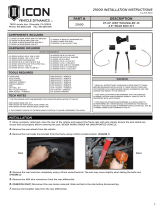
PART # DESCRIPTION
21010 07-UP JEEP WRANGLER JK
4.5” FRONT BOX KIT
21010 INSTALLATION INSTRUCTIONS
COmPONENTS INCLUDED
(1) 124000 JK FRONT TRACK BAR LIFT BRACKET
(2) 124014 JK FRONT BUMPSTOP SPACER
(1) 127004 JK DRAG LINK
(1) 21010H JK FRONT 4.5” HARDWARE KIT
HARDwARE INCLUDED
(2) 120038 JK BRAKE LINE DROP
(1) 127001 JK STEERING FLIP ADAPTER STEM
(1) 127002 JK STEERING FLIP TOP DOME
(1) 127003 JK STEERING FLIP TAPER SLEEVE
(1) 295511 JM12T ROD END
(2) 605052 1/4-20 NYLOCK NUT
(4) 605053 1/4 FLAT WASHER
(2) 605054 1/4-20 X .750 BOLT
(3) 605101 3/8-16 X 1.000 BOLT
(2) 605117 3/8-16 X 3.500 ALLEN BOLT
(7) 605122 3/8-16 C-LOCK NUT
(10) 605133 3/8 SAE FLAT WASHER
(1) 605150 3/8-16 U-BOLT
(1) 605350 1/2-20 C-LOCK NUT
(2) 605445 9/16-12 x 3.000 BOLT
(2) 605450 9/16-12 C-LOCK NUT
(4) 605455 9/16 FLAT WASHER
(1) 605640 3/4-16 JAM NUT THIN
TOOLS REQUIRED
FLOOR JACK
JACK STANDS
TAPE MEASURE
HAMMER
CRESCENT WRENCH
TORQUE WRENCH
DRILL
3/8” DRILL BIT
7/32” ALLEN WRENCH
8MM SOCKET / WRENCH
10MM SOCKET / WRENCH
15MM SOCKET / WRENCH
16MM SOCKET / WRENCH
18MM SOCKET / WRENCH
19MM SOCKET / WRENCH
21MM SOCKET / WRENCH
3/8” SOCKET / WRENCH
7/16” SOCKET WRENCH
9/16” SOCKET / WRENCH
13/16” SOCKET / WRENCH
3/4” SOCKET / WRENCH
7/8” SOCKET WRENCH
TECH NOTES
1. The following parts are required for complete installation of this kit:
• Part #24010 Front Coil Kit
• Part #21036 or Part #21035 Front Upper Link
• Part #21031 or Part #21030 Front Lower Link
• Part #22016 (07-11 Models) or Part#22014 (12+ Models) Front Driveshaft
• Part #22011 (12+ Models) Exhaust Spacer Kit
wARNING!
** READ ALL INSTRUCTIONS THOROUGHLY FROM START TO FINISH
BEFORE BEGINNING INSTALLATION! IF THESE INSTRUCTIONS ARE
NOT PROPERLY FOLLOWED SEVERE FRAME, SUSPENSION AND TIRE
DAMAGE MAY RESULT TO THE VEHICLE!
** ICON VEHICLE DYNAMICS RECOMMENDS THAT YOU EXERCISE
EXTREME CAUTION WHEN WORKING UNDER A VEHICLE THAT IS
SUPPORTED WITH JACK STANDS.
1. Using a properly rated hydraulic jack, raise the vehicle and support the frame rails with jack stands. Ensure jack stands are secure
and set properly before lowering the hydraulic jack. BE SURE TO NEVER WORK UNDER AN UNSUPPORTED VEHICLE. Remove
wheels.
2. Using (2) 18mm, remove the sway bar link bolts from the axle. Use (1) 18mm and (1) 19mm, remove the front sway bar links from the
sway bar. Set sway bar links aside. These will be used on the front later on.
3. Using a 15mm, disconnect the driveshaft from the front dierential. Using an 8mm, disconnect the driveshaft from the transfer
case. The stock driveshaft will not be reused (FIG. 1). Refer to drive shaft instructions.
4. Using a 21mm, disconnect the steering drag link from the knuckle. To free the taper from the knuckle, use a tie rod splitter or a
hammer (FIG.2). Using a 15mm, loosen the turn buckle, and unthread the drag link from the collar.(LEFT HAND THREAD)
5. (2012 models) With a 10mm, remove the front brake line bracket from the axle (FIG.3). Free the lower bracket from the coil seat.
(2007-2011 models do not have this bracket)
6. Using a 21mm, remove the front track bar from the axle. The axle may move slightly when taking the bolt out.
7. Remove the front breather tube from the front dierential.
BEGIN INSTALLATION
FIG.1

2
8. (RUbICON) Disconnect the locker control wires from the front dierential. Red tab slides to the side to unlock connector. (FIG.4)
9. While supporting the front axle with a floor jack, remove front shocks using a 16mm for the stem and (2) 18mm for the lower bolt.
The shock may spin when you try to remove the stem hardware you will need to hold onto the shock body if this happens. The shocks
are limiting droop so MAKE SURE THE AXLE IS SUPPORTED OR THE AXLE WILL FALL when the shocks are removed.
10. Once the shocks are removed, slowly lower the axle while watching for any lines that might snag. Lower the axle enough to
remove the front coils. Carefully remove coils.
11. Refer to upper and lower link instructions and install upper and lower links now.
12. Install the front track bar bracket: slide the new bracket into the stock track bar mount on the axle and position around the axle
tube. Install the factory bolt through the lower hole in the stock position using blue thread locker. Install the U-bolt around the axle as
shown and fasten with supplied 3/8” lock nuts and washers. Install all 4 of the 3/8” x 1.0” bolts [Torque to 35 ft-lbs] (FIG. 5).
13. If ICON adjustable track bar (Part #21020) has been purchased, install the track bar to the bracket using the supplied 9/16” bolt,
washers, and nut [Torque to 115 ft-lbs].
14. Install the front bumpstop spacers by drilling a 3/8” hole in the middle of the lower spring seat where the bumpstop hits using the
supplied template. (FIG. 6)
15. As you install the front coil springs, hold the bumpstop spacer in the spring. Carefully lower the axle far enough to allow access
for the new coils, watch for wiring and hoses that may be stretched. Make sure the factory upper spring isolator is in the upper bucket.
Make sure the pig tail (lower end) of the spring is seated properly (FIG. 7).
FIG.4
FIG.5
FIG.6 FIG.7
FIG.2 FIG.3

3
16. Once the spring is in place, bolt the bump stop spacer to the spring seat through the coil using the allen bolts supplied with a
7/32” allen, and a 9/16” [Torque to 20 ft-lbs].
17. Slowly lift the axle making sure the coils align in the upper and lower seats. Lift the axle just high enough to install the new front
shocks. Be careful not to lift vehicle o of stands.
18. Refer to shock instructions for details on shock and reservoir installation.
19. Thread the drag link into the factory turn buckle. Make sure the drag link and factory tie rod end have equal thread engagement.
20. Install the steering flip adapter: The 5/8” shank end goes down through the steering arm and the taper sleeve adapter is inserted
up around the stem from the bottom, start the nut. Slide the drag link rod end onto the adapter followed by the upper dome spacer
and 1/2” nut. Tighten the 5/8 bottom nut using a 15/16” [Torque to 100 ft-lbs]. Tighten the top nut using a 3/4” [Torque to 75ft*lb].
Tighten rod end jam nut to 150ft-lb.
21. If the steering adaptor is not properly installed as seen in pictures, failure will occur. (FIG.8, FIG.9)
22. Reconnect the front breather tube to the dierential.
23. Install front sway bar links(originally rear sway bar links removed earlier): Use (2) 18mm for the lower bolt and (1) 18mm and (1)
19mm for the upper stud.
24. Disconnect the upper brake line bracket from the frame.(10mm) Connect the brake line drop bracket (Part # 120038) using the
stock bolt with the oset going under the frame. Carefully straighten the hard line without kinking it. Connect to the brake line drop
bracket using a 7/16” and the supplied 1/4” hardware. Torque 1/4” hardware to 10 ft-lbs.
25. Bend the 90 degree angle in the brake line down approximately 20 degrees without kinking it. (FIG. 10)
26. (2012+ models) Reconnect the brake line bracket to the axle using a 10mm.
27. (RUbICON) Reconnect the front locker solenoid. Slide red tab back into place locking connection.
28. Install the ICON driveshaft (07-11 models Part #22016) (12+ models Part #22014) and the exhaust spacer kit (12+ models Part
#22011) using the provided instructions.
29. Certain Jeep packages came equipped with a skid plate that will still interfere with the aftermarket drive shaft at full extension.
Trimming of the skid plate is required for those models.
30. Tighten all factory hardware to factory specs.
31. With vehicle on the ground and wheels straight, loosen the turn buckle on the drag link using a 15mm. Adjust the length of the
drag link by turning to turn buckle until the steering wheel is centered. Tighten the turn buckle.
32. Failure to center the steering wheel before driving will result in computer stability control issues.
33. Align vehicle. It is recommended that you have your vehicle professionally aligned whenever lift components are installed. A
certified alignment technician with lifted vehicle experience is highly recommended.
FIG.8 FIG.9
FIG.10 FIG.11
RETORQUE ALL NUTS, BOLTS AND LUGS AFTER 100 MILES AND PERIODICALLY THEREAFTER.
VERIFY ALL FASTENERS ARE PROPERLY TORQUED BEFORE DRIVING VEHICLE.

4
ICON VEHICLE DYNAMICS LIMITED LIFETIME WARRANTY
Icon Vehicle Dynamics warrants to the original retail purchaser who owns the vehicle on which the product was originally
installed. Icon Vehicle Dynamics does not warrant the product for finish, alterations, modifications and/or installation contrary to
Icon Vehicle Dynamics instructions. Icon Vehicle Dynamics products are not designed, nor are they intended to be installed on
vehicles used in race applications, for racing purposes or for similar activities. (A “race” is defined as any contest between two
or more vehicles, or a contest of one or more vehicles against the clock, whether or not such contest is for a prize). This warranty
does not include coverage for police or taxi vehicles, race vehicles, or vehicles used for government or commercial purposes. Also
excluded from this warranty are sales outside of the United States of America and Canada.
Icon Vehicle Dynamics’ obligation under this warranty is limited to the repair or replacement, at Icon Vehicle Dynamics’ discretion,
of the defective product. Any and all costs of removal, installation or re-installation, freight charges and incidental or consequential
damages are expressly excluded from this warranty. Items that are subject to wear are not considered defective when worn and are
not covered.
Icon Vehicle Dynamics components must be installed as a complete kit as shown in our current application guide. Any substitutions
or exemptions of required components will immediately void the warranty. Some finish damage may happen to parts during
shipping and is not covered under warranty.
This warranty is expressly in lieu of all other warranties expressed or implied. This warranty shall not apply to any product that has
been improperly installed, modified or customized subject to accident, negligence, abuse or misuse.
FOLLOW US ON FACEBOOK!
7929 Lincoln Ave. Riverside, CA 92504 Phone: 951.689.ICON Fax: 951.689.1016
www.iconvehicledynamics.com
/
