Page is loading ...

THE INFORMATION CONTAINED IN THIS DRAWING IS
THE SOLE PROPERTY OF SYNERGY MFG. ANY
REPRODUCTION IN PART OR WHOLE WITHOUT THE
WRITTEN PERMISSION OF SYNERGY MFG IS
PROHIBITED.
Revisions
Rev.
Description
Date
Approved
A
Initial Release Per ECO 18-120
11/5/18
A.S.
Jeep Wrangler 2” Lift Starter
Suspension System
Installation Instructions
Applications:
2018+ Jeep Wrangler 2 Door (JL)
2018+ Jeep Wrangler 4 Door (JLU)
TITLE:
JEEP WRANGLER STARTER SYSTEM
INSTALLATION INSTRUCTIONS
SIZE
DWG NO:
REV
A
JL-STARTER-INST
A
SCALE: N/A
PAGE 1 OF 9

JEEP WRANGLER STARTER SYSTEM
INSTALLATION INSTRUCTIONS
DOC NO. JL-STARTER-INST PAGE 2 OF 8
Thank you for purchasing the best aftermarket products available for your vehicle. We strongly feel that the
parts you are about to install should meet or exceed your expectations for performance. Proper assembly is
critical to the performance of these components and the vehicle as a whole. Please take the time to carefully
read these instructions and familiarize yourself with the installation procedure before working on your
vehicle. If you have any questions PLEASE contact Synergy Manufacturing BEFORE beginning
installation. Thanks again for supporting Synergy – enjoy the performance benefits of the best aftermarket
products available for your vehicle!
Synergy Manufacturing
Phone: (805) 242-0397
Email: [email protected]
Now for the lawyer part:
Modifying or otherwise altering vehicle components may cause the vehicle to handle differently than
originally designed. It is the driver’s responsibility to familiarize themselves with the performance and
handling characteristics of the modified vehicle. Vehicles with larger diameter than stock tires must be
driven carefully and cannot be expected to perform as stock or meet OEM performance with regard to
handling, braking or crash performance. Ensure all replacement components are compatible with vehicle
capacities so as not to overload components, especially tires. It is up to the individual to ensure that the
vehicle and all components are compatible with the intended vehicle use, including load ratings, road
conditions, and driver abilities. Thorough and frequent vehicle inspections are recommended to ensure a
safe and reliable state of readiness, especially after off-highway use.

JEEP WRANGLER STARTER SYSTEM
INSTALLATION INSTRUCTIONS
DOC NO. JL-STARTER-INST PAGE 3 OF 8
Parts List
8820-2010 JEEP JL 2 DOOR STARTER SYSTEM
QTY
Part Number
Description
1
8863-10
Jeep JL Front Lift Springs W/Lower Isolators – 2.0” 2 Door (Pair)
1
8864-10
Jeep JL Rear Lift Springs – 2.0” 2 Door (Pair)
2
8057-10
Jeep Bump Stop Spacer Kit (2-4”)
1
8860-01
Jeep JL Rear Sway Bar Links
1
8886-02
Jeep JL Rear Sway Bar Drop Brackets
1
8855-02
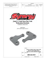
Jeep JL Front Sway Bar Link Relocation Brackets
1
8815-01
Jeep JL Front Lower Shock Relocation Brackets
1
8874-01
Jeep JL Adjustable Rear Lower Shock Brackets
8840-2010 JEEP JLU 4 DOOR STARTER SYSTEM
QTY
Part Number
Description
1
8863-20
Jeep JLU Front Lift Springs W/Lower Isolators – 2.0” 4 Door (Pair)
1
8864-20
Jeep JLU Rear Lift Springs – 2.0” 4 Door (Pair)
2
8057-10
Jeep Bump Stop Spacer Kit (2-4”)
1
8860-01
Jeep JL Rear Sway Bar Links
1
8886-02
Jeep JL Rear Sway Bar Drop Brackets
1
8855-02
Jeep JL Front Sway Bar Link Relocation Brackets
1
8815-01
Jeep JL Front Lower Shock Relocation Brackets
1
8874-01
Jeep JL Adjustable Rear Lower Shock Brackets
General Notes
• These instructions are also available on our website; www.synergymfg.com. Check the website
before you begin for any updated instructions and additional photos and videos for your reference.
• These instructions are intended as a supplement to the instructions included with each of the
components in this kit. These instructions describe the best way to install all of these components
together. For specific instructions, reference the instructions included with each product.
• This system is designed to improve the off-road and on-road performance of the Jeep while allowing
for larger tires to be installed. This is considered a Starter System. For improved performance, many
additional options are available from Synergy Manufacturing. See www.synergymfg.com for
additional systems and upgrade paths.
• Synergy Manufacturing coil springs are much longer than the stock springs to allow for additional
wheel travel. Because of this, spring installation can be challenging without proper tools and
experience. We recommend a coil spring compressor with interchangeable yokes such as the
Fairmount 31655 or similar.
• For non-Rubicon package Jeeps that will be used off road, we HIGHLY recommend our front sway
bar disconnect kit, part number 8859-01.

JEEP WRANGLER STARTER SYSTEM
INSTALLATION INSTRUCTIONS
DOC NO. JL-STARTER-INST PAGE 4 OF 8
TOOLS NEEDED
• Wrenches and Sockets, both SAE and metric
• Torque Wrench
• Spring Compressor (Recommended)
• Angle grinder
• 11/32” Drill Bit and Drill
• Center Punch
• Spray Paint
ESTIMATED INSTALLATION TIME
2-3 Hours
INSTALLATION
Rear of Vehicle
1. Start with the vehicle on flat, level ground. Make sure the vehicle is in gear or park and the front
wheels are chocked. If working on the ground, raise vehicle up and place frame on jack stands.
Support axle with jackstands.
2. Remove rear wheels and tires.
3. Remove the lower shock bolts (18mm socket and wrench).
4. Remove the sway bar end links with a 18mm socket and wrench for the lower bolt and a 18mm
wrench and a 6mm allen key for the upper stud. The 6mm allen is to prevent the stud from spinning.
These will be re-used on the front, so be sure and save them.
INSTALLING 8874-01 REAR LOWER SHOCK BRACKETS
5. With a grinder and cut off wheel, cut the welds on the factory lower shock brackets. Remove the
shock brackets and grind the welds clean. DO NOT CUT OFF THE SWAY BAR LINK TABS.
6. Install the 8874-01 rear shock relocation brackets on the axle in the highest position. Use the original
sway bar mounting bolt and nut to hold the bracket on. Install a 5/16” nut, bolt, and washer in the
upper bracket hole. The washer goes on the outside under the bolt head. It’s easiest to hold the nuts
with a box end wrench on the back side and turn the bolts as they go through the brackets and catch
the nut. Hand tighten the upper 5/16” bolt at this time.
7. With the bracket loosely installed, mark the lower non-slotted hole location. Mark and center punch
the third bolt hole down on the bracket from your top bolt.
8. Remove the bracket and pilot drill the previously marked hole with an 1/8” drill, then use an 11/32”
drill bit to finish the hole.
9. Paint any bare metal surfaces to help prevent rust. Move on to next steps to allow paint to dry.
INSTALLING 8886-02 REAR SWAY BAR DROP BRACKETS

JEEP WRANGLER STARTER SYSTEM
INSTALLATION INSTRUCTIONS
DOC NO. JL-STARTER-INST PAGE 5 OF 8
10. Remove the two bolts holding the driver side rear sway bar bracket to frame (15mm socket). Discard
hardware.
11. Loosen, but do not remove, hardware holding the passenger side rear sway bar bracket to frame
(15mm socket). The sway bar should be loose and able to move.
12. Install an 8886-02 spacer block in between the driver side frame and sway bar bracket. Loosely
install the provided hardware with a washer under the bolt head.
13. Remove the passenger side bracket from frame and discard hardware.
14. Install an 8886-02 spacer block in between passenger side frame and sway bar bracket. Loosely
install the provided hardware with a washer under the bolt head.
15. Make sure the brackets and sway bar are centered. Torque mounting hardware to 35 lb-ft (17mm
socket).
INSTALLING 8057-10 REAR BUMP STOP SPACERS
16. Install a single lower bump stop spacer through the forward hole on the stock bump stop pads.
Torque hardware to 35 lb-ft.
17. Install a cap on each of the bump stop spacers for a total of 2” of bump stop spacing (minimum
required, see Table 1 at end of instructions for recommended bump stop spacing). The cap can be
‘snapped’ on to the lower spacer with a mallet or a large prybar.
INSTALLING 8864 REAR SPRINGS
18. Remove the brake line bracket from the axle with a 10mm wrench.
19. Loosen, but do not remove, the frame side and axle side track bar bolts (21mm socket).
20. Loosen, but do not remove, all control arm hardware (axle side and frame side).
21. If the vehicle is a Rubicon model, remove the rear locker wiring harness from the differential.
Remove the parking brake cables from the caliper and tabs on the axle.
22. If working with the vehicle on the ground, it is easiest at this point to support the center of the axle
with a floor jack and remove the jackstands from under the axle. If using a lift, lower the axle.
23. Lower the axle far enough to remove the rear springs and upper isolators. Be very careful not to
damage any brake lines or electrical lines.
24. Install the upper isolators on the Synergy springs.
25. The new Synergy springs are stamped with a part number. The last two digits of the part number
indicate which side of the vehicle they go on. The -01 is the driver side (left) spring. The -02 is the
passenger side (right) spring.
26. Install the Synergy rear springs, making sure the upper isolators are properly seated. There is a ‘nub’
on the top of the upper spring isolator that must fit into a hole in the spring perch on the frame.
27. With the springs in place raise the axle back up to prevent them from falling out. Replace jack stands
under axle.
INSTALLING 8860-01 REAR SWAY BAR LINKS
28. After allowing the paint to dry, bolt the shock relocation brackets back onto the control arm mounts
with the provided hardware. Bolts should be installed from the back forward with a washer under the
bolt head and the serrated flange nut on the inside of the control arm brackets. Leave bolts slightly
loose.
29. Install the Synergy sway bar links. The tie rod end goes into the sway bar, with the nut on the inside
of the bar, towards the frame. The bushing end of the link attaches to the axle, just as the stock end
link, on the outside of the axle tab (towards the wheel/tire).
30. It may be necessary to use a 14mm open end wrench on the flats on the stud to prevent the stud from
turning while tightening the nut (15mm wrench)
31. Torque the sway bar link hardware. Torque lower bolts to 60 lb-ft and upper nut to 50 lb-ft.
32. Tighten the jam nut with a 19mm wrench, using an 18mm wrench to hold the tie rod end.
33. Torque the shock mount bracket 5/16” bolts to 20 lb-ft.

JEEP WRANGLER STARTER SYSTEM
INSTALLATION INSTRUCTIONS
DOC NO. JL-STARTER-INST PAGE 6 OF 8
34. Raise the axle up (use a tall jack stand to support the front of the vehicle if it is on a lift) or lower the
vehicle down so that the rear shocks fit into the mounting brackets. Install the shocks, using the
original lower shock hardware and torque to 74 lb-ft.
35. Re-install the brake line brackets, locker wiring and parking brake cables.
REINSTALLING WHEELS AND FINAL TORQUE (MAY BE DONE AFTER FRONT IS DONE)
36. Re-install wheels and tires (if removed) and put vehicle back on the ground. Make sure the
suspension is settled by rocking it back and forth carefully.
37. Torque the track bar hardware to 90 lb-ft with the vehicle on the ground at ride height.
38. Torque the lower control arm hardware to 90 lb-ft with the vehicle on the ground at ride height.
39. Torque the upper control arm frame side bolts to 120 lb-ft and axle side hardware to 95 lb-ft with the
vehicle on the ground at ride height.
Front Of Vehicle
1. Start with the vehicle on flat, level ground. Make sure the vehicle is in gear or park and the front
wheels are chocked. If working on the ground, raise vehicle up and place frame on jack stands.
Support axle with jackstands.
2. Remove front wheels and tires.
3. Remove the sway bar end links with an 18mm socket and wrench for the lower bolt and an 18mm
wrench and a 6mm allen key for the upper stud. The 6mm allen is to prevent the stud from spinning.
Save hardware.
4. Loosen but do not remove the frame side and axle side track bar bolts (21mm socket).
5. Loosen but do not remove all control arm hardware (21mm socket).
6. Remove the brake line brackets from lower control arms (15mm socket) and coil mounts (10mm
socket).
7. Disconnect the electrical plug from the front axle disconnect. If the vehicle is a Rubicon model,
remove the front locker harness from the differential. Loosen wiring by removing zip ties and clips.
8. Remove the lower shock bolts (18mm socket) and remove shocks from axle side bracket.
9. If working with the vehicle on the ground, it is easiest at this point to support the axle with a floor
jack and remove the jackstands from under the axle. Due to the differential being off to one side it
may be difficult to lower the axle evenly.
10. With axle fully lowered, remove the stock springs. Remove the springs by unseating them from the
lower spring perch and removing the bottom towards the rear of the vehicle.
11. Pay close attention to orientation of upper spring isolators. Do not remove from the bump stop tube.
12. Remove the lower spring isolators. These are hard plastic and clipped to the axle.
INSTALLING 8855-02 FRONT SWAY BAR RELOCATION BRACKETS
13. Install the Synergy sway bar relocation brackets. Brackets are not right/left specific. They have a
radius to accommodate the axle tube. Insert relocation brackets in between stock axle side sway bar
link brackets and coil mounts. It may be necessary to tap brackets into place with a mallet.
14. Loosely install an M12 bolt through the stock sway bar mount and the Synergy sway bar link
relocation bracket. Use a washer under the head of the bolt and under the nut. We recommend
installing the hardware with the bolt head facing ‘out’ towards the wheel/tire.
15. Align the inner Synergy sway bar link relocation bracket hole with the hole in the lower spring perch.
Loosely install an M12 bolt through the spring perch and the Synergy sway bar link relocation
bracket. Use a washer under the head of the bolt and under the nut. We recommend installing the
hardware with the bolt head facing ‘out’ towards the wheel/tire.
16. With both pieces of hardware installed, tighten and torque to 70 lb-ft.
INSTALLING 8863 FRONT SPRINGS

JEEP WRANGLER STARTER SYSTEM
INSTALLATION INSTRUCTIONS
DOC NO. JL-STARTER-INST PAGE 7 OF 8
17. Install the new Synergy lower spring isolators.
18. The new Synergy springs are stamped with a part number. The last two digits of the part number
indicate which side of the vehicle they go on. The -01 is the driver side (left) spring. The -02 is the
passenger side (right) spring. The flat end of the spring is the bottom.
19. Install a single lower bump stop spacer through the hole in the center of the axle side spring pad.
Torque hardware to 35 lb-ft. Accessing the driver side nut can be done from either the front or the
back of the spring perch. The passenger side can only be accessed from the rear.
20. Install the new Synergy springs, being careful to ensure the upper spring isolators are correctly
oriented. There is a ‘nub’ on the top of the upper spring isolator that must fit into a hole in the spring
perch on the frame.
21. With the springs in place, raise the axle back up to prevent them from falling out. Replace jack
stands under axle.
22. Install a cap on each of the bump stop spacers for a total of 2” of bump stop spacing (minimum
required, see table for recommended bump stop spacing). The cap can be ‘snapped’ on to the lower
spacer with a mallet or a large prybar.
INSTALLING 8815-01 FRONT LOWER SHOCK EXTENSIONS
23. Install the new front lower shock extensions inside the stock OEM shock mounts on the axle. The
upper mounting ears go forward.
24. Loosely install the 1/2-13 x 3” long bolt, 2 washers, and a 1/2-13 top lock nut through the stock shock
eyelet on the axle mounts. Then install the 5/16-18 x 1” bolt and washer up from the bottom and
5/16-18 top lock nut and washer on top. Repeat for the other side.
25. Torque all the shock extension bolts at this point. 1/2” hardware torque to 35 lb-ft, 5/16” hardware
torque to 20 lb-ft.
26. Install the sway bar end links, removed from the rear of the vehicle, in the front with factory
hardware. The bushing end of the link attaches to the axle, on the inside of the tab (towards the
center of the vehicle). It may be necessary to use a 6mm allen key to prevent the upper stud from
spinning. It is necessary to re-use the factory flag nut on the passenger side. The sheet metal ‘flag’
may be removed if desired. Torque lower bolts to 60 lb-ft and upper nuts to 50 lb-ft.
27. Raise the axle up (use a tall jack stand to support the rear of the vehicle if it is on a lift) or lower the
vehicle down so that the rear shocks fit into the mounting brackets.
28. Bolt the shocks into the upper mounting ears. A prybar and round punch can be helpful to line the
shock eyelet up with the hole in the mounting ears. Reuse the OEM shock bolts and torque to 74 lb-
ft.
29. Re-install brake line brackets, front axle disconnect and locker wiring (if so equipped).
REINSTALLING WHEELS AND FINAL TORQUE
30. Re-install wheels and tires (if removed) and put vehicle back on the ground.
31. Torque track bar hardware to 90 lb-ft with the vehicle on the ground at ride height.
32. Torque lower control arm hardware to 190 lb-ft with the vehicle on the ground at ride height.
33. Torque upper control arm hardware to 80 lb-ft with the vehicle on the ground at ride height.
INSTALLATION IS COMPLETE
CHECK ALL BOLT TORQUES AFTER APPROXIMATELY 100 MILES OF DRIVING, AND
AFTER EACH OFF-ROAD TRIP.

JEEP WRANGLER STARTER SYSTEM
INSTALLATION INSTRUCTIONS
DOC NO. JL-STARTER-INST PAGE 8 OF 8
Table 1. Jeep Wrangler JL Recommended Bump Stop Spacing
Wrangler
Model
Fenders
Wheel
Backspacing
Tire
Size
Bump Stop
Spacing
Rubicon
Unmodified Stock
Stock
37 Inch
3 Inch
Rubicon
Unmodified Stock
Stock
35 Inch
2 Inch
Rubicon
Unmodified Stock
4.5 Inch or less
37 Inch
4 Inch
Rubicon
Unmodified Stock
4.5 Inch or less
35 Inch
3 Inch
Rubicon
Trimmed Stock or High Clearance
Stock
37 Inch
2 Inch (Optimal)
Rubicon
Trimmed Stock or High Clearance
Stock
35 Inch
2 Inch
Rubicon
Trimmed Stock or High Clearance
4.5 Inch or less
37 Inch
3 Inch
Rubicon
Trimmed Stock or High Clearance
4.5 Inch or less
35 Inch
2 Inch
Non-Rubicon
Unmodified Stock
Stock
35 Inch
3 Inch
Non-Rubicon
Unmodified Stock
Stock
33 Inch
2 Inch
Non-Rubicon
Unmodified Stock
4.5 Inch or less
35 Inch
4 Inch
Non-Rubicon
Unmodified Stock
4.5 Inch or less
33 Inch
3 Inch
Non-Rubicon
Trimmed Stock or High Clearance
Stock
35 Inch
2 Inch (Optimal)
Non-Rubicon
Trimmed Stock or High Clearance
Stock
33 Inch
2 Inch
Non-Rubicon
Trimmed Stock or High Clearance
4.5 Inch or less
35 Inch
3 Inch
Non-Rubicon
Trimmed Stock or High Clearance
4.5 Inch or less
33 Inch
2 Inch
Table 2. Jeep Wrangler JL Bolt Torques
Bolted Joint Location
Wrench Size
Torque
Front Upper Control Arm
18mm
80 lb-ft
Front Lower Control Arm
21/24mm
190 lb-ft
Front Brake Mount to Control Arm
15mm
15 lb-ft
Front Track Bar
21mm
110 lb-ft
Front Sway Bar Relocation Bracket
17mm
70 lb-ft
Front Sway Bar End Links
18mm
60 lb-ft
Front Upper Control Arm Heat Shields
10mm
40 lb-in
Lower Shock (Front and Rear)
18mm
75 lb-ft
Rear Upper Control Arm to Frame
21mm
120 lb-ft
Rear Upper Control Arm to Axle
21mm
95 lb-ft
Rear Lower Control Arm
21mm
90 lb-ft
Rear Sway Bar Brackets to Frame
17mm
35 lb-ft
Rear Sway Bar Link to Axle
18mm
60 lb-ft
Rear Sway Bar Link to Sway Bar
15mm
50 lb-ft
Rear Shock Relocation Bracket Hardware
½”
20 lb-ft
Bump Stop Spacers
¼” Allen Key
35 lb-ft
Front Shock Relocation Through Bolt
¾”
35 lb-ft
Front Shock Relocation Lower Bolt
½”
20 lb-ft
/


