Page is loading ...

1
7929 Lincoln Ave. Riverside, CA 92504
Phone: 951.689.ICON Fax: 951.689.1016
PART # DESCRIPTION
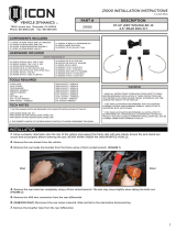
22026 18-UP JEEP JL 2.5” LIFT REAR
DUAL RATE SPRING KIT
22026 INSTALLATION INSTRUCTIONS
WARNING!
** READ ALL INSTRUCTIONS THOROUGHLY FROM START TO FINISH
BEFORE BEGINNING INSTALLATION! IF THESE INSTRUCTIONS ARE
NOT PROPERLY FOLLOWED SEVERE FRAME, SUSPENSION AND TIRE
DAMAGE MAY RESULT TO THE VEHICLE!
** ICON VEHICLE DYNAMICS RECOMMENDS THAT YOU EXERCISE
EXTREME CAUTION WHEN WORKING UNDER A VEHICLE THAT IS
SUPPORTED WITH JACK STANDS.
** ICON VEHICLE DYNAMICS RECOMMENDS ALL INSTALLATION TO
BE PERFORMED BY A PROFESSIONAL SHOP/SERVICE TECHNICIAN.
PRODUCT FAILURE CAUSED BY IMPROPER INSTALLATION WILL NOT BE
COVERED UNDER ICON’S WARRANTY POLICY.
1. Using a properly rated jack, raise the rear of the vehicle and support the frame rails with jack stands. Ensure the jack stands are
secure and set properly before lowering the jack. NEVER WORK UNDER AN UNSUPPORTED VEHICLE. Remove the rear wheels.
2. Remove the sway bar links from the axle using (2) 18mm. Remove the sway bar links from the sway bar using a 6mm allen wrench
and an 18mm. Set the links aside as they will be reused in the front. [FIGURE 1]
COMPONENTS INCLUDED
(2) 124059 SWAY BAR LINK 10.250 OFFSET
(2) 128001 18-UP JL REAR BUMP STOP SPACER
(1) 128006 18-UP JL .25” REAR COIL SHIM
(2) 128513 18-UP JL 2.5” REAR COIL SPRING
(1) 22026H 18-UP JL 2.5” REAR HARDWARE KIT
HARDWARE INCLUDED
22026H HARDWARE KIT
(4) 605075 5/16-18 X 1.500 FLATHEAD SCREW
(4) 605076 5/16-18 C-LOCK NUT
(3) 605016 5/16 FLAT WASHER
(8) 297024 HAT BUSHING 1.005 X .620 X .755
(4) 209202 SLEEVE .625 X .509 X 1.475
(2) 605854 M12-1.75 X 70MM CAP SCREW
(2) 605838 M12-1.75 FLANGED NYLOCK NUT
TOOLS REQUIRED
JACK
JACK STANDS
PLIERS
FLATHEAD SCREW DRIVER
TORQUE WRENCH
5/32” ALLEN WRENCH
1/2” SOCKET / WRENCH
16MM SOCKET / WRENCH
18MM SOCKET / WRENCH
TECH NOTES
1. THE SUPPLIED COIL SHIM IS USED TO ACCOUNT FOR THE DIFFERENCE IN HEIGHTS FROM SIDE TO
SIDE AND CORRECT A PASSENGER SIDE LEAN.
4-02-2018 REV.A
INSTALLATION
FIG.1

2
3. Remove the parking brake cable from the brake drum link using pliers. Remove the parking brake cable front the axle housing using
a flathead screw driver, push the spring catch inward to release it from the mount. [FIGURE 2 & 3]
4. RUBICON ONLY* Disconnect the rear locker plug on the rear dierential.
5. Loosen the lower shock mount bolt using an 18mm socket/wrench. [FIGURE 4]
6. Using a floor jack, lift the axle enough to remove the tension from the lower mount, then remove the shock bolts. Slowly lower the
axle taking care to not overextend or damage any lines. Lower the axle enough to remove the tension from the coil springs.
7. Remove the coil springs and remove the upper spring isolator from the coil spring. [FIGURE 5 & 6]
8. Place the upper spring isolators on the supplied (128513) spring and install. Install the coil spring with the part number right side
up to ensure that the spring is not installed upside down. Check to make sure the end of the pigtail is seated properly on the isolator.
Install the supplied coil spring shim on the passenger side, on top of the isolator.
9. Lift the axle while locating the pin on the upper spring isolator into the hole in the spring seat. Also, make sure the center of the
isolator catches and centers on the cone in the spring seat. If installed incorrectly, the spring isolator will not be centered on the cone
of the spring seat and may result in damage as well as lift height variance. [FIGURE 7]
10. Mount the ICON shocks using the supplied hardware and two 18mm socket/wrenches. [Torque to factory spec] [FIGURE 8]
FIG.6FIG.5
FIG.3FIG.2
FIG.4
FIG.8FIG.7

3
11. Fasten the bump stop spacers to the bump stop striker pads using the supplied 5/16” hardware. Use a 5/32” allen and a 1/2” open
end wrench. [Torque to 17 ft-lbs]
12. Grease the rear sway bar link bushings and sleeves then assemble the rear sway bar links. Mount the sway bar links using the
supplied hardware with a 16mm and 18mm socket/wrench. Ensure that the head of the bolt is facing towards the wheel.
[Torque to 65 ft-lbs]. Use the factory lower bolt to mount the sway bar link to the axle. [Torque to factory spec] [FIGURE 9 & 10]
13. RUBICON ONLY* Plug in the rear locker connector on the rear dierential.
14. Connect the parking brake cable to the axle mount and the brake drum link. [FIGURE 11]
15. Install the wheels and lower the vehicle to the ground. [Torque lugs to factory spec]
RETORQUE ALL NUTS, BOLTS AND LUGS AFTER 100 MILES AND PERIODICALLY THEREAFTER.
VERIFY ALL FASTENERS ARE PROPERLY TORQUED BEFORE DRIVING VEHICLE.
FIG.11
FIG.10FIG.9

4
ICON VEHICLE DYNAMICS LIMITED LIFETIME WARRANTY
ICON Vehicle Dynamics warrants to the original retail purchaser who owns the vehicle on which the product was originally
installed. ICON Vehicle Dynamics does not warrant the product for finish, alterations, modifications and/or installation contrary
to ICON Vehicle Dynamics instructions. ICON Vehicle Dynamics products are not designed, nor are they intended to be installed
on vehicles used in race applications, for racing purposes or for similar activities. (A “race” is defined as any contest between two
or more vehicles, or a contest of one or more vehicles against the clock, whether or not such contest is for a prize). This warranty
does not include coverage for police or taxi vehicles, race vehicles, or vehicles used for government or commercial purposes. Also
excluded from this warranty are sales outside of the United States of America and Canada.
ICON Vehicle Dynamics’ obligation under this warranty is limited to the repair or replacement, at ICON Vehicle Dynamics’
discretion, of the defective product. Any and all costs of removal, installation or re-installation, freight charges and incidental or
consequential damages are expressly excluded from this warranty. Items that are subject to wear are not considered defective
when worn and are not covered.
ICON Vehicle Dynamics components must be installed as a complete kit as shown in our current application guide. Any
substitutions or exemptions of required components will immediately void the warranty. Some finish damage may happen to parts
during shipping and is not covered under warranty.
This warranty is expressly in lieu of all other warranties expressed or implied. This warranty shall not apply to any product that has
been improperly installed, modified or customized subject to accident, negligence, abuse or misuse.
FOLLOW US ON FACEBOOK!
7929 Lincoln Ave. Riverside, CA 92504 Phone: 951.689.ICON Fax: 951.689.1016
www.iconvehicledynamics.com
/


