Page is loading ...

DLite rental display
Installation manual
R5976149/04
09/07/2004

Barco nv Events
Noordl
aan 5, B-8520 Kuurne
Phone: +32 56.36.89.70
Fax: +32 56.36.88.24
E-mail:
Visit us at the web: www.barco.com
PrintedinBelgium

Changes
Barco provides this manual ’as is’ without warranty of any kind, either expressed or implied, including but not limited to the implied war-
ranties or merchantability and fitness for a particular purpose. Barco may make improvements and/or changes to the product(s) and/or the
program(s) described in this publication at any time without notice.
This publication could contain technical inaccuracies or typographical errors. Changes are periodically made to the information in this
publication; these changes are incorporated in new editions of this publication.
Copyright ©
All rights reserved. No part of this document may be copied, reproduced or translated. It shall not otherwise be recorded, transmitted or
stored in a retrieval system without the prior written consent of Barco.
Guarantee and Compensation
Barco provides a guarantee relating to perfect manufacturing as part of the legallystipulated terms of guarantee. On rece
ipt, the purchaser
must immediately inspect all delivered goods for damage incurred during transport, as well as for material and manufacturing faults Barco
must be informed immediately in writing of any complaints.
The period of guarantee begins on the date of transfer of risks, in the case of special systems and software on the date of commissioning,
at latest 30 days after the transfer of risks. In the event of justified notice of compliant, Barco can repair the fault or provide a replacement
at its own discretion within an appropriate period. If this measure proves to be impossible or unsuccessful, the purchaser can demand a
reduction in the purchase price or cancellation of the contract. All other claims, in particular those relating to compensation for direct or
indirectdamage, and also damage attributed to the operation of software as well astootherservicesprovidedbyBarco,beingacomponent
ofthesystemorindependentservice, willbedeemedinvalidprovided the damageis not proven to be attributed to the absence of properties
guaranteed in writing or due to the intent or gross negligence or part of Barco.
If the purchaser or a third party carries out modifications or repairs on goo
ds delivered by Barco, or if the goods are handled incorrectly,
in particular if the systems are commissioned operated incorrectly or if, after the transfer of risks, the goods are subject to influences not
agreed upon in the contract, all guarantee claims of the purchaser will be rendered invalid. Not included in the guarantee coverage are
system failures which are attributed to programs or special electroni
c circuitry provided by the purchaser, e.g. interfaces. Normal wear as
well as normal maintenance are not subject to the guarantee provided by Barco either.
The environmental conditions as well as the servicing and maintenance regulations specified in the this manual must be complied with by
the customer.
Trademarks
Brand and product names mentioned in this manual may be trade
marks, registered trademarks or copyrights of their respective holders.
All brand and product names mentioned in this manual serve as comments or examples and are not to be understood as advertising for
the products or their manufactures.
Federal Communications Commission (FCC Statement)
This equipment has been tested and found to comply with the limits for a class A digital device, pursuant to Part 15 of the FCC rules.
These limits are designed to provide reasonable protection against harmful interference when the equipment is operated in a commercial
environment. This equipment generates, uses, and can radiate radio frequency energy and, if not installed and used in accordance with
the instruction manual, may cause harmful interference to radio communications. Operation of this equipment in a residential area may
cause harmful interference, in which case the user will be responsible for correcting any interference.


Table of contents
TABLE OF CONTENTS
1. Safety.................................................................................................................. 3
1.1 Safetyguidelines...................................................................................................................... 3
1.2 ImportantSafetyInstructions ......................................................................................................... 4
1.3 ImportantWarnings ................................................................................................................... 4
2. Systemoverview.................................................................................................... 7
2.1 Introduction............................................................................................................................ 7
2.2 DLitedisplaytiles...................................................................................................................... 8
2.2.1 IntroductionDLitedisplaytiles................................................................................................. 8
2.2.2 SpecificationsDLitetiles ....................................................................................................... 9
2.2.2.1 SpecificationsDLite7.................................................................................................... 9
2.2.2.2 SpecificationsDLite10 .................................................................................................. 9
2.2.2.3 SpecificationsDLite14 .................................................................................................10
2.2.3 DimensionsDLitetiles.........................................................................................................11
2.3 DLiterentalstructures................................................................................................................11
2.3.1 IntroductionDLiterentalstructures ...........................................................................................11
2.3.2 SpecificationDLiterentalstructures..........................................................................................12
2.3.2.1 Specification2x2DLiterentalstructure...............................................................................12
2.3.2.2 Specification2x3DLiterentalstructure...............................................................................12
2.3.3 DimensionsDLiterentalstructures...........................................................................................13
2.4 DLiterentalflightcases..............................................................................................................14
2.4.1 IntroductionDLiterentalflightcases..........................................................................................14
2.4.2 SpecificationsDLiterentalflightcases........................................................................................15
2.4.3 DimensionsDLiterentalflightcases..........................................................................................15
2.4.4 ImportantwarningsconcerningDLiterentalflightcases.....................................................................15
2.5 DLiterentalsetupaccessories.......................................................................................................16
2.6 CablesforDLitedisplays ............................................................................................................17
2.6.1 PowercablesforDLitedisplays...............................................................................................17
2.6.2 DatacablesforDLitedisplays ................................................................................................18
2.7 Powerboxes..........................................................................................................................19
2.8 Digitizer...............................................................................................................................19
2.9 Fiberlinksystem......................................................................................................................19
2.10 Controlsoftware......................................................................................................................19
3. Setup acompleteDLiterentaldisplaysystem...............................................................21
3.1 SetupafloormountDLiterentaldisplay............................................................................................21
3.2 Set up a hanging DLite rental display ...............................................................................................21
4. Basicsetupprocedures..........................................................................................23
4.1 LocatingDLiterentalstructureparts.................................................................................................23
4.2 Closing the safety lock mechanism..................................................................................................24
4.3 Closingthelockclamp...............................................................................................................25
4.4 Opening the DLite flight case ........................................................................................................26
4.5 ClosingtheDLiteflightcase.........................................................................................................27
4.6 RemovingDLiterentalframesoutoftheflightcase................................................................................27
4.7 PlacingDLiterentalframesintotheflightcase .....................................................................................28
4.8 Attaching DLite rental truss beam with a DLite rental structure ....................................................................29
4.9 SecuringaDLiterentaltrussbeam..................................................................................................30
4.10 InstallingDLiterentalfeet............................................................................................................30
4.11 Installingtheadjustablefoot.........................................................................................................32
4.12 InstallingaDLitestacker.............................................................................................................32
4.13 AttachaDLiterentalstructureonaDLiterentalfoot ...............................................................................34
4.14 AttachandsecureDLiterentalstructuresontopofeachother....................................................................35
4.15 AttachandsecureDLiterentalstructuresnexttoeachother ......................................................................36
4.16 AttachandsecureaDLiterentalstructureintoaDLitedisplay ....................................................................36
4.17 BuildupafloormountedDLiterentaldisplay.......................................................................................37
4.18 Build up a hanging DLite rental display with truss beams ..........................................................................38
4.19 WallTrim..............................................................................................................................41
5. CablingofaDLiterentaldisplay ................................................................................43
5.1 DLite tile connectivity.................................................................................................................43
5.2 PowercablingofaDLiterentaldisplay..............................................................................................43
5.3 DatacablingofaDLiterentaldisplay................................................................................................45
6. Maintenance.........................................................................................................49
6.1 Cleaning DLite tiles...................................................................................................................49
7. Servicing.............................................................................................................51
7.1 Safetyinstructions....................................................................................................................51
7.2 RemoveaDLitetile..................................................................................................................51
7.2.1 FrontaccessofaDLitetile....................................................................................................51
7.2.2 RearaccessofaDLitetile....................................................................................................53
7.2.3 Simultaneous front and rear access of a DLite tile ...........................................................................54
R5976149 DLITE RENTAL DISPLAY 09/07/2004
1

Table of contents
7.3 InsertaDLitetile.....................................................................................................................55
7.3.1 FrontaccessofaDLitetile....................................................................................................55
7.3.2 RearaccessofaDLitetile....................................................................................................56
7.4 HotswapofaDLitetile ..............................................................................................................58
7.5 RearaccessofaDLitetilewithanobstructedbackexit............................................................................59
Index......................................................................................................................61
2 R5976149 DLITE RENTAL DISPLAY 09/07/2004

1. Safety
1. SAFETY
1.1 Safety guidelines
Personal protection
Image 1-1
Warning
Image 1-2
Suspended loads
Image 1-3
Hard hat
Image 1-4
Mind your fingers
Be aware of suspende
d loads, wear a hard hat to reduce the risk of personal injury. Mind your fingers while working with heavy
loads.
Installation personnel
This installation must be performed by authorized and qualified technical personnel only.
Accredited safety officers must ensure the safety of the site, construction, assembly, connection, use, dismantling, transport etc. of
such safety cri
tical systems.
Caution
Installation should be performedonly after you are thoroughly familiar with all of the proper safety checks andinstallation instructions.
To do otherwise increases the risk of hazards and injury to the user.
Assembly parts are designed for intended use only in conjunction with Barco LED walls.
Do not modify and/or replicate any component. Barco uses specific materials and manufacturing processes in order to achieve part
strength. Consult Barco for assistance with custom applications.
Always follow Barco installation instructions. Contact Barco if you should have any question regarding the safety of an application.
The manufacturer assumes no liability for incorrect, inadequate, irresponsible or unsafe assembly of systems.
Product care
Structural & mounting components should be kept dry, clean, lubricated (only if recommended), coated properly, and otherwise
maintaine
d in a manner consistent with part design. Barco products must be used in a manner consistent with their design and
inspected on a routine basis for security, wear, deformation, corrosion and anyother circumstances that may affect the loadhandling
capability of the part.
Barco recommends inspections at regular intervals for all installations and increasing in frequency for more critical installations. If
a part is found to have damage, which may cause a decrease in load capability, the part must be removed for service or replaced
immediately.
Under no circumstances are Barco parts repairable by anyone other than Barco.
R5976149 DLITE RENTAL DISPLAY 09/07/2004
3

1. Safety
1.2 Important Safety Instructions
Instructions:
• Read these instructions.
• Keep these instructions.
• Heed all warnings.
• Follow all instructions.
• IMPORTANT, plug holder clamps must be locked firmly on all display tile units and power boxes to prevent the possible ingress
of fluids or solid particles. Replace damaged clamps or seals immediately.
• Do NOT submerge fully or partly in water or other liquids.
• Clean only with materials or chemicals that are inert, nonabrasive, noncorrosive and non-marking. Consult the manufacturer
for further advice should any doubts exist regarding any cleaning procedure.
• Do not block ventilation openings. Install in accordance with the manufacturers instructions.
• Do not install near any heat sources such as radiators, heat registers, stoves, or other apparatus (including amplifiers) that
produce heat.
• Do not defeat the safety purpose of the polarized or grounding type plugs/sockets. If the provided sockets / plugs are damaged
then replacement of the defective parts must be undertaken immediately.
• Protect the power/data cords from being walked on or pinched particularly at plugs, convenience receptacles, and the point
where they exit from the apparatus. Replace damaged power/data cords immediately.
• Only use attachments/accessories specified by the manufacturer.
• Disconnect the power to this apparatus during lightning storms or provide suitable additional lightning protection. Unplug this
apparatus when unused for long period of time.
• Refer all servicing to qualified service technicians/personnel. Servicing is required when the apparatus has been damaged in
any way, such as power-supply cord or plug is damaged, the apparatus does not operate normally, or has been dropped.
• Useonly with systemsor peripherals specifiedby themanufacturer, or sold with the apparatus. Use caut
ion during lifting/moving
or transporting to avoid damage by possible tipping.
1.3 Important Warnings
Important Warnings:
• Risk of electric shock:
Image 1-5
Risk of electrical shock
Risk of electric shock. Do not open. To reduce the
risk of electric shock, do not remove cover (or back). No user-serviceable
parts inside. Refer servicing to qualified service personnel.
The lightning flash with an arrowhead within a triangle is intended to tell the user that parts inside this product may cause a risk
of electrical shock to persons.
The exclamation point within a triangle is intended to tell the user that important operating and/or servicing instructions are
included in the technical documentation for this equipment.
• Maximum ambient temperature:
The maximum recommended ambient temperature for the LED wall is 50 °C, the minimum temperature is -20 °C.
4
R5976149 DLITE RENTAL DISPLAY 09/07/2004

1. Safety
• High leakage current:
The combination of multiple tiles in an installation results in increased levels of leakage current. In order to avoid risk of electric
shock due to high leakage current, proper grounding of the installation is required.
• Risk of personnel injury:
Secure all tiles in the rack. As a supplementary safeguard, and in order to protect against the risk of personnel injury, each tile
should be attached to the rack by a safety cable.
• Flammable materials:
Keep flammable materials away from the installation (such as curtains). A lot of energy is transferred into heat. The installation
should be such that the amount of air flow required for safe operation of the equipment is not compromised. Proper ventilation
must be provided.
• Risk of electric shock / Risk of fire:
Power cables and connectors have been designed with special properties for outdoor use, and resistance against ingress of
water. Use only the factory recommended power cables and connectors. Using other cables and connectors may result in risk
of electric shock and risk of fire.
To protect against risk of fire by overloading of power cables, MAXIMUM 6 TILES may be connected in parallel. Each source
cable supplying a branch of MAXIMUM 6 TILES should be protected by a circuit breaker or fuses rated 16 A / 250 V.
• Disconnect device:
When the appliance inlets of the individual tiles are not accessible, the socket outlets supplying the rack sha
ll be installed near
the equipment and be easily accessible, or a readily accessible general disconnect device shall be incorporated in the fixed
wiring.
• This equipment MUST be earthed:
In order to protect against risk of electric shock, the installation should be properly grounded. Defeating the purpose of the
grounding type plug will expose you to the risk of electric shock.
• Power system:
It is recommended to use a TN-S power distribution system (a power distribution system with a separate neutral and grounding
conductor) in order to avoid large ground currents loops due to voltage differences in the neutral conductor. The total electrical
installation should be protected by an appropriate rated disconnect switch, circuit break
ers and Ground Fault Current Inter-
rupters. The installation shall be done according to the local electrical installation codes. In Europe special attention should be
given to EN 60364, the standard for electrical installation of buildings. In Germany VDE 0100 should be adhered to.
• Mains cords:
The power cords deliveredwith this systemhave specialproperties for safety. They are not user serviceable. If the power cords
are damaged, replace only with new ones. Never try to repair a power cord.
R5976149 DLITE RENTAL DISPLAY 09/07/2004
5

1. Safety
6 R5976149 DLITE RENTAL DISPLAY 09/07/2004

2. System overview
2. SYSTEM OVERVIEW
Overview
• Introduction
• DLite display tiles
• DLite rental structures
• DLite rental flight cases
• DLite rental setup accessories
• Cables for DLite displays
• Power boxes
• Digitizer
• Fiberlink system
• Control software
2.1 Introduction
The fundamental elements of a DLite rental display are:
• DLite display tiles.
• DLite rental structures.
• DLite rental foot, foot beams and stacker or DLite rental truss beams.
• Power box.
• Digitizer.
• Control software.
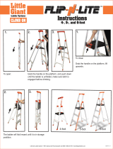
Block diagram DLite rental display system:
Sources Digitizer
Control
PC
Power
box
RS232
Tile 1
LED-wall
Tile 2
Tile 3
Image 2-1
Block diagram DLite system.
R5976149 DLITE RENTAL DISPLAY 09/07/2004 7

2. System overview
2.2 DLite display tiles
2.2.1 Introduction DLite display tiles
Introduction
The DLite tiles are the solution to the - until recently - unsolved problem of a full color video picture in the outdoors. Addressing the
huge need of brightness together with the required water-resistant, it is a display that provides a "best of breed" video and/or data
picture outside in any weather without any supplemental sheltering.
The modular concept of the display still enables easy installation and maintenance of the display. Built-in intelligence provides for
auto calibration of the full display, hot swap and diagnostic capabilities.
An extremely rugged tile, confers an IP65 rating to the whole DLite display. An aluminium cast protects all the electronics in a self
enclosed environment. This provides unrivaled resistance to external nuisance as long-term outdoor exposure to sa
lty air, corrosive
intrusion, ...
A hot swap capability enables to service a display module while the rest of the display keeps on playing.
A very exclusive sourcing of the LED component combined with the Barco processing expertise ensures extreme brightness level,
even at full white on a color calibrated wall. This brightness is guaranteed through time due to t
he very long lifetime of the LED
components used in the Barco DLite tiles.
An unique video processing feature enables to create a visual resolution quasi doubles the physical resolution defined by the cluster
of LED’s spread on the surface of the display. Barco’s Dual Pixel Technology confers to the DLite range a picture smoothness and
an enhanced resolution that makes it even suitable for shorter viewing distances or indoor applications in some instances.
Image 2-2
DLite tile rear view.
Order info
Article No. Description
R9004005 DLite 7 display tile
R9004026 DLite 10 display tile
R9004015 DLite 14 display tile
Do not use other tiles than those specified in the “Order info” table.
8 R5976149 DLITE RENTAL DISPLAY 09/07/2004

2. System overview
2.2.2 Specifications DLite tiles
2.2.2.1 Specifications DLite 7
Specifications
Visual Resolution 7,0 mm
Physical Resolution 14,0 mm
Hor. viewing angle
120° (min.50% brightness)
Vert. viewing angle
60° (min.50% brightness)
Tile dimensions
width: 448mm (17.6")
height: 448mm (17.6")
depth: 195mm (7.7")
Temperature range
operating : -20°C - 40°C (-4 - 104°F)
storage : -20°C - 60°C (-4 - 140°F)
Brightness 6500 NIT
5000 NIT (calibrated @ 6500°K)
Lifetime 50 000 h (full white - half brightness)
Processing color : +10 bit
LED configuration 2R, 2G, 1B
Pixel density
20.407/m² (1.898/ft²)
4.096/tile
Power consumption
maximum: 250 W / Tile
average: 62 W / Tile
Weight / Tile 14 Kg / 30,8 lbs (excluding structure)
Colors
1,07 billion
Refresh rate 400 Hz minimum (PAL / NTSC)
Humidity
operating: 10 - 99%
storage: 10 - 99%
D320 input compatibility
S-Video - Composite - YUV - RGB - SDI - HDSDI - Data DVI up to UXGA
Certifications UL-CE-TUV-FCCClassA
2.2.2.2 Specifications DLite 10
Specifications
Screen size
Unlimited
Weight 14 kg
Visual Resolution 9,3 mm
Physical Resolution 18,6 mm
Hor. viewing angle
120°
(min. 50% brightness)
Vert. viewing angle
60°
(min. 50% brightness)
R5976149 DLITE RENTAL DISPLAY 09/07/2004 9

2. System overview
Avg Power Consumption 90 VA / tile
Max Power Consumption 350 VA / tile
Tile dimensions Width: 0,448 m
Height: 0,448 m
Depth: 0,195 m
Optimal viewing distance
15 meter
Outdoor Compliance
IP 65
Temperature range operating:
-20°C <> 40°C
storage:
-20°C <> 60°C
Brightness 6.500 NIT
Calibrated Brightness 5000 NIT ± 10% (calibrated @ 6500°K)
Contrast Ratio
1000 : 1
Lifetime 50.000h [half brightness]
Processing +10bit
Source compatibility S-Video - Composite - YUV - RGB - SDI - HDSDI - Data DVI up to UXGA
Refresh rate 400 Hz minimum (PAL / NTSC)
2.2.2.3 Specifications DLite 14
Specifications
Contrast Ratio
1.000 : 1
Screen size
Unlimited
Weight 14 kg
Visual Resolution 14,0 mm
Physical Resolution 28,0 mm
Hor. viewing angle
120°
(min. 50% brightness)
Vert. viewing angle
60°
(min. 50% brightness)
Avg Power Consumption 90 VA / tile
Max Power Consumption 350 VA / tile
Tile dimensions Width: 0,448 m
Height: 0,448 m
Depth: 0,195 m
Optimal viewing distance
20 meter
Outdoor Compliance
IP 65
10 R5976149 DLITE RENTAL DISPLAY 09/07/2004

2. System overview
Temperature range operating:
-20°C <> 40°C
storage:
-20°C <> 60°C
Brightness 6.500 NIT
Calibrated Brightness 5000 NIT ± 10% (calibrated @ 6500°K)
Lifetime 50.000h [half brightness]
Processing +10bit
Source compatibility S-Video - Composite - YUV - RGB - SDI - HDSDI - Data DVI up to UXGA
Refresh rate 400 Hz minimum (PAL / NTSC)
2.2.3 Dimensions DLite tiles
Dimensions
448
4
4
8
195
92
Image 2-3
Dimensions given in millimeters.
2.3 DLite rental structures
2.3.1 Introduction DLite rental structures
Introduction
The DLite rental structures are designed to enable ultra fast build up and breakdown of an outdoor rental LED display. They consist
in a 2 x 2 and a 2 x 3 configuration (H x V). The build up process is streamlined, for easy and safe operations.
R5976149 DLITE RENTAL DISPLAY 09/07/2004
11

2. System overview
Image 2-4
DLite rental structures.
Order info
Article no. Description
R9850570 2 x 2 DLite rental structure.
R9850160 2 x 3 DLite rental structure.
2.3.2 Specification DLite
rental structures
2.3.2.1 Specification2x2DLiterentalstructure
Specification
Compatibility 2x2 structure can be used in combination with 2x3 structure to achieve full flexibility.
Width stucture 896mm+2.5mm
Height structure 896 mm + 40 mm
Depth structure 355 mm
Weight frame
45 kg
High precision positioning
2 large positioning cones for primary positioning
2 smaller positioning
cones
Truss build-up 14 tiles high
Foot build-up 8 tiles high
H clamps capacity
700 kg + safe workload
Accessibility & servicing Front & rear accessibility of display module
Registred approval
TUV approved for safety
2.3.2.2 Specification2x3DLiterentalstructure
Specification
Compatibility 2x3 structure can be used in combination with 2x2 structures to achieve full flexibility.
Width stucture 896mm+2.5mm
Height structure 1344 mm + 40 mm
Depth structure 355 mm
Weight frame
63 kg
12 R5976149 DLITE RENTAL DISPLAY 09/07/2004

2. System overview
High precision positioning
2 large positioning cones for primairy positioning
2 smaller positioning cones
Truss build-up 15 tiles high
Foot build-up 9 tiles high
H clamps capacity
700 kg + safe workload
Accessibility & servicing Front & rear accessibility of display module
Registred approval
TUV approved for safety
2.3.3 Dimensions DLite rental structures
Dimensions2x2DLiterentalstructure
896 285
8
9
6
Image 2-5
Dimensions gi
ven in millimeters.
R5976149 DLITE RENTAL DISPLAY 09/07/2004 13

2. System overview
Dimensions2x3DLiterentalstructure
896
285
1
3
8
4
Image 2-6
Dimensions given in millimeters.
2.4 DLite rental flight cases
2.4.1 Introduction DLite rental flight cases
Introduction
The DLite rental flight case holds up two ren
tal structures with tiles mounted inside and is specifically designed to enable fast build
up directly from flight case to display. There are two different sizes of DLite rental flight cases. One for the 2 x 2 rental structures
and one for the 2 x 3 rental structures.
Image 2-7
Order info
Article No. Description
R9850580
DLite rental flight case for 2 rental structures of 2 x 2.
R9850180
DLite rental flight case for 2 rental structures of 2 x 3.
14 R5976149 DLITE RENTAL DISPLAY 09/07/2004

2. System overview
2.4.2 Specifications DLite rental flight cases
Specifications
Width flight case
1010 mm
Depth flight case
810 mm
Height flight case Flight case for 2 x 2 rental structures : 1170 mm
Flight case for 2 x 3 rental structures : 1610 mm
Weight flight case (empty) Flight case for 2 x 2 rental structures : 90 kg
Flight case for 2 x 3 rental structures : 114 kg
2.4.3 Dimensions DLite rental flight cases
Dimensions
1010 mm 1010 mm810 mm
1170 mm
1610 mm
810 mm
Image 2-8
Dimensions given in millimeters.
2.4.4 Important warnings concerning DLite rental flight cases.
Important warnings concerning transport and stack of DLite rental flight cases.
• Maximum stack two (2) DLite rental flight cases high. Never higher.
• Surface on which flight case is standing must be level to ensure that the total load is evenly spread out among the four wheels.
The surface mu
st also be able to support the load safely.
• Before stacking or transporting flight cases, check the wheels and their fixation screws for wear or defects.
• Before stacking or transporting flight cases, check that the DLite rentals are securely locked into the base of the flight case.
• Before stacking or transporting flight cases, check the four lock handles on each flight case are in good working order and
locked securely.
• When stacked, make sure the wheels of the upper flight case are precisely positioned in the stacking dishes of the flight case
below.
• Stacked flight cases may not be moved. Before stacking, the lower flight case must already be in its final resting position before
placing the second upon it.
• Never stack loa
ded flight cases in a truck or other transport medium, unless each flight case is rigidly strapped tight.
• In the event of a wheel breaking, flight cases must be rigidly strapped tight to prevent a stack collapsing.
• Use an appropriate forklift to raise flight cases and take the necessary precautions to avoid personnel injury.
R5976149 DLITE RENTAL DISPLAY 09/07/2004
15

2. System overview
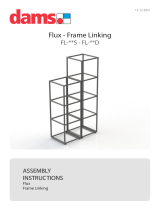
2.5 DLite rental setup accessories
Base stand setup accessories
A
B
C
EDF
Image 2-9
A Rental foot beam of 4 meter length.
B Rental foot beam of 2,4 meter length.
C Rental foot beam of 1,2 meter length.
D Adjustable foot.
E DLite rental foot.
F DLite rental stacker (stacker tube and mounting accessories).
Truss setup accessories
A
B
Image 2-10
A DLite single truss beam.
B DLite dual truss beam.
Order info
Article No. Description
R9851915
Two rental foot beams of 4 meter.
R9850176
Two rental foot beams of 2,4 meter.
R9850177
Two rental foot beams of 1,2 meter.
R9851470
Four adjustable feed. To level out the rental foot beams.
R9850510
DLite rental foot. For indoor or outdoor base stand rental displays.
16 R5976149 DLITE RENTAL DISPLAY 09/07/2004
/