Page is loading ...

EVERLAST
POWER MTS 252STi
Rev. 1 0 10501-18
everlastwelders.com
1-877-755-9353
Specicaons and Accessories subject to change without noce.
329 Lileeld Ave. South San Francisco, CA 94080 USA
Operator’s Manual for the PowerMTS 252STi
Safety, Setup and General Use Guide
A Digitally-Controlled, Multi-Process MIG/AC-DC TIG/Stick Welder
SMAW
PULSE
GMAW
CC
CV
IGBT
GTAW
AC/DC

2
Table of Contents
Section……………………………………………….Page
Letter to the Customer …………………....…………
Everlast Contact Information…………….………….
Safety Precautions……………………………………
Introduction and Specifications…..…………………
Overview of Parameters and Specifications…….
Technical Parameters……………………………...
General Description, Purpose and Features…….
Set Up Guide and Component Identification….…...
Connections and Polarity………………………….
Installing The Wire Spool………………………….
Polarity/Gas/Amp Recommendations……………
Front View Middle Panel……………………….……
Middle Panel Item Description and Explanation..
Front View/Control Panel…………………………….
Control Panel Item Description and Explanation..
Side View …………………………………..…….......
Side View Item Description and Explanation..…..
Rear View Back Panel……………………………….
Rear Panel Item Description and Explanation…..
Basic Theory and Function………………………….
MIG Operation…..…………………………………….
MIG Operation (Diagrams)…………..………………
Special Notes Concerning Operation………….…
Stick Operation………………………………………..
Basic TIG Operation………………………………….
TIG Arc Starting…………………………………….
Tungsten Preparation……………………………..
Pulse TIG Operation………………………………….
AC TIG Operation…………………………………….
TIG Work Sheets…………………………………...
25 Series MIG Torch………………………………
25 Series Consumables…………………………..
24 Series MIG Torch………………………………
24 Series Consumables…………………………..
26/18 Series TIG Torch……………………...……
Trouble Shooting Guide…………...………………...
Error Codes…………………………………………
3
4
5
9
9
10
11
14
14
23
24
26
27
28
39
36
37
38
39
40
40
45
48
50
52
54
55
56
58
61
64
65
66
67
68
70
71

3
Dear Customer,
THANKS! You had a choice, and you bought an Everlast product. We appreciate you as a valued customer and
hope that you will enjoy years of use from your welder.
Please go directly to the Everlast website to register your unit and receive your warranty informaon. Your unit
registraon is important should any informaon such as product updates or recalls be issued. It is also important
so that we may track your sasfacon with Everlast products and services. If you are unable to register by web-
site, contact Everlast directly through the sales department at the main customer service number in your country.
Your unit’s warranty will be registered and in full eect. Keep all informaon regarding your purchase, including
date of purchase and receipt. In the event of a problem with your unit or other issue you must contact technical
support before your welder can be a candidate for warranty service and returned. An over-the-phone review/
diagnosis must be performed BEFORE a RMA will be issued or before the unit can be sent in for service.
Please read the warranty statement published online and other important informaon found on the Everlast
website of the division located in or nearest to your country. This includes the terms of the purchase and war-
ranty procedure. Print it for your records and become familiar of its terms and condions. Please note that
Guns, accessories and torches are covered under a separate, shorter warranty. Please be sure you visit the web-
site and are familiar with all the warranty terms before you call for service.
Everlast oers full technical support, in several dierent forms. We have online support available through email,
and a welding support forum designed for our customers and non-customers to interact with each other. Tech-
nical advisors are acve on the forum daily. We also divide our support into two divisions: technical and welding
performance. Should you have an issue or queson concerning your unit, please contact performance/technical
support available through the main company headquarters available in your country. This support is free to all
Everlast customers. For best service call the appropriate support line and follow up with an email, especially dur-
ing weekends, holidays or any o hours when you cannot reach a live person. In the event you do not reach a live
person, leave a message and your call will normally be returned within 24 hours, except for weekends and holi-
days. Also, for quick answers to your basic quesons, join the company owned forum available through the web-
site. You’ll nd knowledgeable sta available to answer your quesons. You also may nd a topic that already
addresses your queson at hp://www.everlastgenerators.com/forums/. Should you need to call or write, always
know your model name, purchase date and welder manufacturing inspecon date. This will assure the quick and
accurate customer service. REMEMBER: Be as specic and informed as possible. Technical and performance
advisors rely upon you to carefully describe the condions and circumstances of your problem or queson.
Take notes of any issues as best you can. You may be asked many quesons by the advisors to clarify problems
or issues that may seem very basic. However, diagnosis procedures MUST be followed to begin the warranty
process. Advisors can’t assume anything (even with experienced users) and must cover all aspects to properly
diagnose the problem. Depending upon your issue, it is advisable to have basic tools handy such as screwdriv-
ers, wrenches, pliers, and even an inexpensive test meter with volt/ohm funcons before you call.
Let us know how we may be of service to you should you have any quesons.
Sincerely,
Everlast Customer Service

4
Serial number: _____________________________
Model number: _____________________________
Date of Purchase:___________________________
Contact Information
Everlast US:
Everlast consumer satisfaction email: sales@everlastwelders.com
Everlast Website: everlastwelders.com
Everlast Technical Support: support@everlastwelders.com
Everlast Support Forum: http://www.everlastgenerators.com/forums/index.php
Main toll free number: 1-877-755 WELD (9353) 9am—5pm PST M-F
11am-4pm PST Sat.
FAX: 1-650-588-8817
Everlast Canada:
Everlast consumer satisfaction email: sales@everlastwelders.ca
Everlast Website: everlastwelders.ca
Everlast Technical Support: sales@everlastwelders.ca
Telephone: 905-630-8246 9am-4:30pm EST M-F
Everlast Australia:
Sydney: 5A Karloo Parade Newport NSW 2106
(02) 9999 2949
Port Macquarie: 2B Pandorea Place Port Macquarie
(02) 6584 2037
After hours support: 0410 661 334
Everlast Technical Support: [email protected]
OTHER (Please record here for your records):

5
Everlast is dedicated to providing you with the best possible equipment and service to meet the
demands of the welding applicaons that you have. We want to go beyond delivering a sas-
factory product to you. That is the reason we oer technical support to assist you with your
needs should an occasion occur. With proper use and care your product should deliver years of
trouble free service.
Safe operaon and proper maintenance is your responsibility.
We have compiled this operator’s manual to instruct you in basic safety, operaon and mainte-
nance of your Everlast product to give you the best possible experience. Overall, welding re-
quires experience and common sense to obtain the best results in the safest manner. As thor-
ough as this welding manual may be, it cannot substute for the me, instrucon and
knowledge level required to learn how to weld. Exercise extreme cauon and care in all acvi-
es related to welding or cung. Your safety, health and even life depends upon it. While an
accident is never planned, prevenng an accident requires careful planning.
Please read this manual carefully before you operate your Everlast unit. Do not operate this
welder unl you are thoroughly familiar with its safe and proper operaon. If you feel you
need more informaon please contact Everlast.
The warranty does not cover improper use, maintenance or consumables. Accessories such as
guns, torches regulators, foot pedals etc. are not covered in the unit warranty. They are cov-
ered under a separate warranty. Do not aempt to alter or defeat any piece or part of your
unit, parcularly any safety device. Keep all shields and covers in place during unit operaon
should an unlikely failure of internal components result in the possible presence of sparks and
explosions. If a failure occurs, disconnue further use unl malfunconing parts or accessories
have been repaired or replaced by qualied personnel.
Note on High Frequency electromagnec disturbances:
Certain welding and cung processes generate High Frequency (HF) waves. These waves may
disturb sensive electronic equipment such as televisions, radios, computers, cell phones, and
related equipment. High Frequency may also interfere with uorescent lights. Consult with
an electrician if disturbance is noted. Somemes, improper wire roung or poor shielding may
be the cause.
HF can interfere with pacemakers. See EMF warnings in following safety secon for further in-
formaon. Always consult your physician before entering an area known to have welding or
cung equipment if you have a pacemaker.
Safety Precautions

6
Safety Precautions
These safety precautions are for protection of your safety and
health. Failure to follow these guidelines may result in serious
injury or death. Be careful to read and follow all cautions and
warnings. Protect yourself and others from danger and injury.
Welding and cung processes produce high levels of ultraviolet (UV) radiaon that can cause se-
vere skin burn and damage. There are other potenal hazards involved with welding such as severe
burns and respiratory related illnesses. Therefore observe the following to minimize potenal acci-
dents and injury:
Use appropriate safety glasses with wrap around shields while in the work area, even under weld-
ing helmets to protect your eyes from ying sparks and debris. When chipping slag or grinding, gog-
gles and face shields may be required.
When welding or cung, always use an approved shielding device, with the correct shade of lter
installed. Always use a welding helmet in good condion. Discard any broken or cracked lters or
helmets. Using broken or cracked lters or helmets can cause severe eye injury and burn. Filter
shades of no less than shade 5 for cung and no less than shade 9 for welding are highly recommend-
ed. Shades greater than 9 may be required for high amperage welds. Keep lter lenses clean and
clear for maximum visibility. It is also advisable to consult with your eye doctor should you wear con-
tacts for correcve vision before you wear them while welding.
Do not allow personnel to watch or observe the welding or cung operaon unless fully protected
by a lter screen, protecve curtains or equivalent protecve equipment. If no protecon is availa-
ble, exclude them from the work area. Even brief exposure to the rays from the welding arc can
damage unprotected eyes.
Always wear hearing protecon because welding and cung can be extremely noisy. Ear protec-
on is necessary to prevent hearing loss. Even prolonged low levels of noise has been known to cre-
ate long term hearing damage. Hearing protecon also further protects against hot sparks and debris
from entering the ear canal and doing harm.
Always wear personal protecve clothing. Flame proof clothing is required at all mes. Sparks and
hot metal can lodge in pockets, hems and cus. Make sure loose clothing is tucked in neatly. Leather
aprons and jackets are recommended. Suitable welding jackets and coats may be purchased made
from re proof material from welding supply stores. Discard any burned or frayed clothing. Keep
clothing away from oil, grease and ammable liquids.
Leather boots or steel toed leather boots with rubber booms are required for adequate foot pro-
tecon. Canvas, polyester and other man made materials oen found in shoes will either burn or
melt. Rubber or other non conducve soles are necessary to help protect from electrical shock.
Flame proof and insulated gauntlet gloves are required whether welding or cung or handling met-
al. Simple work gloves for the garden or chore work are not sucient. Gauntlet type welding gloves
are available from your local welding supply companies. Never aempt to weld with out gloves.
Welding with out gloves can result in serious burns and electrical shock. If your hand or body parts
comes into contact with the arc of a plasma cuer or welder, instant and serious burns will occur.
Proper hand protecon is required at all mes when working with welding or cung machines!
This welder contains moving parts that can result in injury. Keep hands, ngers, hair, and loose
clothing away from the wire feeding mechanisms and fans while unit is switched on and in use. Do
not aempt to defeat any safety feature. Always operate unit with guard in place on the wire feeder.

7
Safety Precautions
WARNING! Persons with pacemakers should not weld, cut or be in the welding area unl they
consult with their physician. Some pacemakers are sensive to EMF radiaon and could severely
malfuncon while welding or while being in the vicinity of someone welding. Serious injury or death
may occur!
Welding and plasma cung processes generate electro-magnec elds and radiaon. While the
eects of EMF radiaon are not known, it is suspected that there may be some harm from long term
exposure to electromagnec elds. Therefore, certain precauons should be taken to minimize expo-
sure:
• Lay welding leads and lines neatly away from the body.
• Never coil cables around the body.
• Secure cables with tape if necessary to keep from the body.
• Keep all cables and leads on the same side the body.
• Never stand between cables or leads.
• Keep as far away from the power source (welder) as possible while welding.
• Never stand between the ground clamp and the torch.
• Keep the ground clamp grounded as close to the weld or cut as possible.
Welding and cung processes pose certain inhalaon risks. Be sure to follow any guidelines from
your chosen consumable and electrode suppliers regarding possible need for respiratory equipment
while welding or cung. Always weld with adequate venlaon. Never weld in closed rooms or con-
ned spaces. Fumes and gases released while welding or cung may be poisonous. Take precauons
at all mes.
Any burning of the eyes, nose or throat are signs that you need to increase venlaon.
• Stop immediately and relocate work if necessary unl adequate venlaon is obtained.
• Stop work completely and seek medical help if irritaon and discomfort persists.
WARNING! Do not weld on galvanized steel, stainless steel, beryllium, tanium, copper, cadmium,
lead or zinc without proper respiratory equipment and or venlaon.
WARNING! This product when used for welding or cung produces fumes and gases which con-
tains chemicals known to the State of California to cause birth defects and in some cases cancer.
(California Safety and Health Code §25249.5 et seq.)
WARNING! Do not weld or cut around Chlorinated solvents or degreasing areas. Release of Phos-
gene gas can be deadly. Consider all chemicals to have potenal deadly results if welded on or near
metal containing residual amounts of chemicals.
Keep all cylinders upright and chained to a wall or appropriate holding pen. Certain regulaons re-
garding high pressure cylinders can be obtained from OSHA or local regulatory agency. Consult also
with your welding supply company in your area for further recommendaons. The regulatory changes
are frequent so keep informed.
All cylinders are a potenal explosion hazard. When not in use, keep capped and closed. Store
chained so that overturn is not likely. Transporng cylinders incorrectly can lead to an explosion. Do
not aempt to adapt regulators to t cylinders. Do not use faulty regulators. Do not allow cylinders to
come into contact with work piece or work. Do not weld or strike arcs on cylinders. Keep cylinders
away from direct heat, ame and sparks.

8
Safety Precautions
WARNING! Electrical shock can kill. Make sure all electrical equipment is properly grounded. Do
not use frayed, cut or otherwise damaged cables and leads. Do not stand, lean or rest on ground
clamp. Do not stand in water or damp areas while welding or cung. Keep work surface dry. Do not
use welder or plasma cuer in the rain or in extremely humid condions. Use dry rubber soled shoes
and dry gloves when welding or cung to insulate against electrical shock. Turn machine on or o
only with gloved hand. Keep all parts of the body insulated from work, and work tables. Keep away
from direct contact with skin against work. If ght or close quarters necessitates standing or resng
on work piece, insulate with dry boards and rubber mats designed to insulate the body from direct
contact.
All work cables, leads, and hoses pose trip hazards. Be aware of their locaon and make sure all
personnel in area are advised of their locaon. Taping or securing cables with appropriate restraints
can help reduce trips and falls.
WARNING! Fire and explosions are real risks while welding or cung. Always keep re exnguish-
ers close by and addionally a water hose or bucket of sand. Periodically check work area for smol-
dering embers or smoke. It is a good idea to have someone help watch for possible res while you are
welding. Sparks and hot metal may travel a long distance. They may go into cracks in walls and oors
and start a re that would not be immediately visible. Here are some things you can do to reduce the
possibility of re or explosion:
• Keep all combusble materials including rags and spare clothing away from area.
• Keep all ammable fuels and liquids stored separately from work area.
• Visually inspect work area when job is completed for the slightest traces of smoke or embers.
• If welding or cung outside, make sure you are in a cleared o area, free from dry tender and
debris that might start a forest or grass re.
• Do not weld on tanks, drums or barrels that are closed, pressurized or anything that held amma-
ble liquid or material.
Metal is hot aer welding or cung! Always use gloves and or tongs when handling hot pieces of
metal. Remember to place hot metal on re-proof surfaces aer handling. Serious burns and injury
can result if material is improperly handled.
WARNING! Faulty or poorly maintained equipment can cause injury or death. Proper mainte-
nance is your responsibility. Make sure all equipment is properly maintained and serviced by qualied
personnel. Do not abuse or misuse equipment.
Keep all covers in place. A faulty machine may shoot sparks or may have exploding parts. Touching
uncovered parts inside machine can cause discharge of high amounts of electricity. Do not allow em-
ployees to operate poorly serviced equipment. Always check condion of equipment thoroughly
before start up. Disconnect unit from power source before any service aempt is made and for long
term storage or electrical storms.
Further informaon can be obtained from The American Welding Society (AWS) that relates directly
to safe welding and plasma cung. Addionally, your local welding supply company may have addi-
onal pamphlets available concerning their products. Do not operate machinery unl your are com-
fortable with proper operaon and are able to assume inherent risks of cung or welding.

9
Section 1 Introduction and Specifications
Overview of Parameters and Features*
Power i-MIG 252STi**
MIG/TIG/Sck Amp Range 120V: MIG 30-150A/ TIG DC: 10-150A, AC: 20-150A / Sck 10-120A
240V: MIG 30-250A/ TIG DC: 10-250A, AC: 20-250A / Sck 10-200A
Volt Adjustment Range MIG 120V: 15.5-22V 240V: 15.5-30V
MIG Wire Feed Speed 120V: 60-400 (5-10 m/min) 240V: 60 to 600 IPM (.5-15 m/min)
Input Voltage 120-240V Single phase (208V permissible)
Welder Type Digitally controlled, IGBT inverter type with CV Synergic MIG , /AC-DC Pulse TIG, CC Sck funcons.
Wire Roll Size and Diameter .023”-.062” wire diameters possible with oponal drive rolls. (Oponal Gun required (36 series) for oper-
aon with .062” Wire.)
12” diameter roll (Up to 44 lbs.); 8” adapter available (10-12 lbs.); 4” Diameter NOT SUPPPORTED
Pre/Post Flow Control MIG/TIG MIG: (Pre) 0-10 Seconds/ (Post) 0-10 Seconds; TIG (Pre) 0-10 Seconds/ (Post) 0-10 Seconds
Up/Down Slope of MIG Volts/ TIG Amps MIG: 0-1 Second, TIG: 0-10 Seconds
Synergic MIG/Manual MIG Synergic MIG funcon for wires from .023” to .045” in diameter, with mild steel, stainless and Aluminum
sengs. Synergic feature operates via speed control on MTS version of Spool gun as well. Manual MIG
aords complete and independent control throughout the range of all MIG funcons with no factory
programmed sengs.
MIG Burn Back Timer Control 0-2 seconds
Inductance/Arc Force Control 0-100%
TIG Output Type AC/DC with Pulse Control and Wave Form Selecon
AC TIG Frequency 20-200Hz
AC Balance 30-70% of Electrode Posive (+)
TIG Pulse Frequency .5-150Hz
Base Pulse TIG Amps 3-95% of Peak Amps
TIG Pulse Time On/Balance 5-95%
Memory Saves up to 9 programs.
MIG/TIG Spot and Stch Timer Spot: .5-15 Seconds Stch: 0-15 Seconds
MIG Burn Back Timer 0-2 Seconds
Sck Hot Start Timer 0-2 Seconds
Sck Hot Start Intensity Control 0-100% over set amperage
Sck E6010 Capability Yes
Power Cable Length 9.5 . (3m)
Accessories** 24 Series MIG torch ( some units, 25 Series) torch 9.5 . (3m), 18 Series water-cooled TIG torch (some
units, 26 series), Work clamp with cable 9.5 . (3m). 300 A Sck Torch with cable (3m), Floang ball type
regulator.
Weight: 83 lbs/38 Kg
Recommended Generator minimum***
*See next page for complete electrical and technical data.
**Specicaons and accessories subject to change without noce.
***Any use with a generator must be used with a generator rated as providing “clean power” by the generator manufacturer. This is typically
less than 5% THD. Any use with a generator not cered by its manufacturer as providing clean power may render the warranty void.

10
Bare Weight: 38kg/83 lbs.
*60 IPM is based on minimum useable feed rate.
NOTE: Environment, Maintenance and Safety: Keep this welder at least 18 inches away from all objects for proper cooling.
This unit uses mulple fans at dierent spots within the machine for cooling so proper spacing is imperave from all sides.
Do not exceed 40° C in environment or duty cycle will be reduced. Regularly inspect and clean the welder and circuitry on a
monthly basis with dry compressed air. Remove the covers only aer the unit has been turned o and unplugged for 30
minutes to discharge the capacitors and to prevent the possibility of electrocuon. Do not grind or direct sparks near the
welder to prevent damage to the panel face and internal components. Regular disassembly and cleaning with dry com-
pressed air is highly recommended. Damage/failures resulng from metal/ dust buildup is not covered by the warranty.
MODEL: PowerMTS 252STi Serial No.
EN/ IEC60974.1
240V; DC: 30-250A; 15.5-26.5V 120V; DC: 30-150A; 15.5-21.5V
X 60% 100% 35% 60% 100%
U0 V
74V
I2 250A 200A NA 150A 90A
U2 26.5V 24V NA 21.5V 20V
240V; DC: 10-250A; 10.4-20V
AC: 20A-250A; 10.8-20V
120V; DC: 10-150A; 10.4-16V
AC: 20-150A; 10.8V to 250A/20V
X 60% 100% 35% 60% 100%
U0 V
74V
I2 250A 200A NA NA 150A
U2 20V 18V NA NA 16V
120V; DC 10-120A; 20.4V-24.8V 240V; DC: 10-200A; 20.4– 28V
X 60% 100% 40% 60% 100%
U0 V
74V
I2 200A 160A 120A 90A
U2 28V 26.4V 24.8V 23.6V
1~ 50/60 Hz
U1
120-240V
120V I1MAX: 42.8A I1EFF 34A
240V I1MAX: 44.9A I1EFF 35A
PROTECTION
CLASS
IP21S
COOLING
‘METHOD:
QUAD, FULL-
TIME FANS
INSULATION: F WIRE SPEED:
240V: 60*-600 IPM
120V: 60*-400 IPM
EVERLAST
f1
f2
1~
S
S
S
POWERMTS 252STi
Section 1 Introduction and Specifications

11
General Descripon, Purpose and Features. The Power
MTS 252STi mul-process unit features an industry rst
MIG TIG Sck unit with AC/DC TIG output. As with Ever-
last’s other compact MTS units, this unit employs HF arc
starng for TIG as well as a Li TIG arc start feature.
The TIG capability of this unit is further enhanced by a
completely adjustable pulse. In MIG mode the unit fea-
tures both standard and synergic MIG modes. Synergic
MIG is a useful feature to help simplify set-up and re-
duce the need for extensive operator knowledge of ide-
al volts, amps and wire speed raos. The spool gun
capability of this unit allows the user to weld aluminum
in MIG mode. The oponal Parker spool gun is perfectly
suited to this welder and is a good choice for welding
aluminum at a faster rate than AC TIG typically allows.
But when thinner gauges are required, the TIG oers
capability to weld aluminum down to .023”. The
PowerMTS 252Si also features a synergic funcon for
spool gun use, which is also unique for this welder, al-
lowing control of both amps and volts through one
knob. This welder does not have the tradional bulk of
an undercarriage which is normally associated with mul-
-process welders of this range of capability, helping it
retain portability. In addion, the welder can accom-
modate full size rolls of MIG wire up to 12” in diameter
(up to 44 lbs. typically). A wire spool adapter is availa-
ble which will allow the unit to accept 8” spools. Alt-
hough aer-market 4” spool adapters can be purchased
from many aer-market suppliers, Everlast does not
supply a 4” adapter for the machine. Nor do we recom-
mend it due to concerns with excessive cast and spiral
from the small diameter of the wire roll. As it exits the
gun, it may create a wandering arc. If 4” rolls are typi-
cal of your paern of use, consider the spool gun opon
which is ideal for this type applicaon. The welder is
capable of storing up to 9 programs for rapid setup and
recall of favorite sengs. This feature is helpful when
storing favorite pulse programs. The unit also features
a heavy-duty wire feeding mechanism with 4 driven
drive rolls for maximum wire feeding capability. The
mul-process aspect of this welder features addional
welding processes which include DC TIG and Sck. The
TIG process also features an industry rst for MIG/TIG/
Sck welders: a fully adjustable TIG Pulse seng, which
allows the unit to pulse up to 500 mes a second be-
tween two selected amp values. The TIG process also
features High Frequency (HF) start (which is another
industry rst) to allow contactless starng of the TIG
arc. The PowerMTS seriesi is the rst series of mul-
process units in the industry to feature out-the-front
controls for TIG, which also includes a solenoid con-
trolled gas connecon. See below for addional sum-
mary of features:
1) GMAW Process (MIG). The digitally controlled
MIG components precisely control arc funcons
and give real-me feed back about the welding
output parameters. As already menoned, the
welder is also spool gun (gun oponal) ready for
economical welding of Stainless and Aluminum
wires if needed. The PowerMTS 252STi can also
be used with ux core and dual shield wire (when
equipped with oponal ux core drive wheels.)
However, since there is no Flux-Core/Dual Shield
synergic seng, Flux-Core/Dual Shield operaon
will not be opmized in synergic mode and consid-
erable readjustment may need to be made. Alt-
hough the standard gun is competent to be used
with ux core wire, a special ux core gun may be
necessary for heavy duty Flux core (non-gas) use.
At this me, Everlast does not oer a ux core gun
for this unit. However, many aer-market suppli-
ers of MIG guns do oer special ux-core guns that
can be equipped to t the popular Euro-Style pow-
er connector that the PowerMTS 252STi ulizes.
2) GTAW (TIG). The TIG mode of the welder features
both AC and DC output which is suitable for weld-
ing all metals when required. It includes a high
frequency start and a li start funcon to give the
operator maximum exibility welding in areas that
restrict HF use. A fully adjustable AC mode with AC
wave form selecon feature allows the user to
weld Aluminum and Magnesium. A fully adjustable
pulse feature is also included to help control heat
and distoron. It can also be used to improve bead
appearance. A key feature of this welder’s design
places all connecons on the front of the panel
instead of under the spool cover. No install kits are
necessary to make the unit TIG ready. A gas sole-
noid is used to automacally control gas ow when
the arc is started and stopped according to the
me set on the panel. A foot pedal or torch switch
is used to control the TIG funcon. The pedal con-
trols the amps when plugged in. Similarly, the
torch switch provided with the TIG torch can be
used to control the funcons on the panel se-
quencer graph. The sequencer can be used to pre-
set, amp and slope parameters to work in conjunc-
on with the torch switch. It is also used to control
other aspects of the weld parameters that may be
related to 2T/4T torch switch or foot pedal opera-
on. The unit is ready to TIG weld (with the excep-
on of Tungsten and shielding gas) when it arrives.
Addional TIG consumable kits can be purchased
Section 1 Introduction and Specifications

12
from Everlast which include stubby consumables or
gas lens kits with Tungsten in the kit. Aenon!
Be sure to read all the connecon direcons locat-
ed in this manual and important informaon re-
garding proper connecons of torch and work ca-
ble in TIG mode or damage or improper operaon
may occur.
3) SMAW (Sck). In sck mode the welder delivers a
smooth DC low spaer arc. Professional, high-
quality welds are obtainable with E7018, 7014,
309L, 316L, 6011 and many other similar rods that
are designed for use with any DC sck welder. This
unit is opmized for welding E6010. This seng
also works well with the easier-welding E6011. The
Sck mode also features adjustable hot start me
and hot start intensity controls which are designed
to help reduce scking during arc starts while sim-
ultaneously reducing porosity or inclusions during
arc iniaon. Note: This unit does not provide AC
operaon in sck mode. AC operaon is for TIG
only.
4) Sck Arc Force Control. The arc force control ad-
justs the quality and feel of the welding arc. It does
so by modifying the volt/amp curve. As the voltage
drops below approximately 20 volts when the arc
gap (length) is shortened, the unit reacts by auto-
macally boosng the amps over the original Amp
seng. This helps to prevent the rod from scking
and helps keep the arc going as arc voltage falls.
This acon also boots penetraon and can be used
to change the way the arc feels and acts.
5) Burn Back Control. Burn back control is used to
control the length of the wire sck-out aer the
trigger is released. It helps to prevent the welding
wire from scking in the coalescing weld puddle
aer the arc is terminated and saves the user from
having to trim the wire before restarng the arc.
6) Spot and Stch Timers. The spot mer funcon is
frequently used in fabricaon applicaons where
consistent tack welds are required. The Stch m-
er is used in conjuncon with the spot mer to cre-
ate a regular on/o cycle of the arc while the MIG
gun trigger is held to control heat input and to
make consistent seam weld during producon.
7) Synergic MIG Mode. Synergic mode may be en-
gaged to simplify welder setup and adjustment.
This mode will allow the customer to input basic
parameters and the machine will automacally set
the wire feed speed (amps) and voltage based o
of the user input. The unit’s programming is easily
overridden and the welder will remember the new
rao of voltage to wire feed seng during the ac-
ve welding session unl the process is changed,
or unl the Synergic mode is deselected. The ma-
chine has two synergic modes, one for MIG opera-
on, one for Spool gun operaon. If a seng is
found that is desirable, be sure to save it under a
program number and record it, or the sengs will
be lost once you leave the welding session/mode.
8) Pulse TIG Mode. The pulse TIG feature can be em-
ployed to control heat, wicking of the puddle and
reduce the arc cone diameter, improving the di-
rectability of the arc. The Pulse TIG mode allows
the seng of Pulse Amps, Pulse Frequency, and
Pulse Time-On. Each features serves to change and
shape the welding arc and puddle to control heat,
wet-in and penetraon.
9) Pre and Post Flow Control. The adjustable Pre and
Post ow control features are designed to improve
weld quality at the beginning and end of the weld
where porosity from oxidaon can be a problem.
This is accomplished by providing adjustable me
controls for both pre ow and post ow of shield-
ing gas. This control is acve for both MIG and TIG.
10) MIG Start and Crater Fill (MIG End) Feature im-
proves starts and starts, and helps prevent bead
cracking and porosity in 4T mode.
11) Slow Run-in of Wire. This feature improves arc
striking quality in MIG modes by helping prevent
arc stuering (machine gunning) and push-o dur-
ing arc iniaon by slowing the wire speed unl
the arc is established. Note: This feature does
prevent the user from taking accurate measure-
ments of wire feed speed manually as the wire
will feed slower unl the arc is struck and main-
tained. Adjustments to starng (upslope) may be
made to further improve the arc starng proper-
es of this welder.
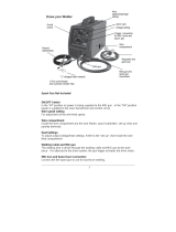
12) Spool Gun Modes. This welder is well equipped to
handle the aluminum welding needs of most cus-
tomers by being both spool gun ready. The unit
can handle several dierent Everlast spool gun
models, but the most capable is the 300 amp, Par-
ker® DSP 360A spool gun. Also the user may want
to consider the Everlast SM200N-MTS gun which is
a 200+ Amp gun with a 24 series barrel, although
the gun will not support the full range of amps the
welder delivers. A spool gun is an economical
choice for light to heavy applicaons requiring a
fast deposion rate of aluminum on materials
3/16” or greater in thickness. A spool gun is lim-
ited to 4” rolls (usually holding 1 lb of aluminum
and 2 lbs of other ller metals) so numerous
spools may be needed on larger projects. Note:
Section 1 Introduction and Specifications

13
This unit does not support push-pull gun opera-
on. It only supports spool gun operaon.
Basic Design and Construcon. This mul-process
welder features an intuive control panel and couples it
with digitally controlled IGBT inverter design that pro-
duces a stable arc while conserving energy. Everlast
ulizes quality components from US, European, and
Asian based companies to ensure reliability and parts
commonality. Major control components are of a mod-
ular, plug- and-play design which allows rapid diagnosis
and repair of the welder. Welding parameters can be
innitely and connuously adjusted throughout the
range, oering instant welding response for maximum
control.
Installaon. The basic construcon of the PowerMTS
252S is rugged and durable. It is considered ideal for
circumstances where portability is of concern. Crical
components are protected by coangs to make the
welder environmentally resistant and has a water in-
gress rang of IP21S, (the standard in the welding indus-
try to protect from vercally dripping water). However,
some common-sense care should be exercised to make
sure that the welder oers the safest and best perfor-
mance. Please note the following items regarding safe
and proper operaons to ensure best service and re-
sults while welding:
1) Do not use the welder in damp or wet areas. Per-
spiraon and other forms of water in contact with
the body can increase the risk of electrocuon.
2) Do not use the welder in extremely corrosive envi-
ronments. To maintain opmum power transfer,
check main connecons, clamps and cables fre-
quently to ensure that components are not corrod-
ed. Excessive dirt, corrosion and oxidaon can re-
sult in an unstable arc and excessive heat build-up.
If the work clamp becomes corroded or damaged,
be sure to replace it with a heavy-duty work clamp
rated for at least 300 amps. If your work clamp
appears to become extremely hot while welding,
and all connecons are clean and secure, replace
the work clamp. Unstable arcs and hard starng,
especially in MIG mode are oen the result of poor
work clamp condion or connecon.
3) Store the welder covered with a moisture and re
resistant material.
4) If used on a mobile cart, strap or x the welder to
the cart so that accidental overturn is not likely.
Duty Cycle/Overcurrent/Under Voltage/Overvoltage
Warnings. Thanks to a quad cooling fan design, the
PowerMTS 252STi has a duty cycle rang of 60% at 250
Amps while welding in MIG and TIG mode and a rang
of 60%@ 200 Amps while welding in sck mode(240V).
The duty cycle rang is the amount of me (expressed
as a percentage) out of 10 minutes the unit can weld
without a rest. For MIG, the unit is capable of welding 6
minutes out of every 10 minutes at the maximum out-
put of 250 Amps. For the balance of the 10 minute
period, the unit should be allowed to rest and cool
while running. This rang is based o a 40° C maxi-
mum temperature. If the unit’s duty cycle has been
exceeded, the Stop LED will come on and unit will cease
welding output. An error code of “E04”will be displayed
If a duty cycle event has occurred. Allow the unit to run
and cool for 15 minutes. Aer 15 minutes of cooling
the unit while switched on without welding, cycle the
power switch to reset the unit. In the event of an over-
current, the welding output will cease and the “Stop”
LED will come on and an error code of EO2 will be dis-
played. In duty cycle and overcurrent events, the wire
may connue to feed without output. Overcurrent
events can be caused by too low of supply voltage, run-
ning on undersized extension cords, too large of wire
diameter, too high of sengs for wire diameter, too
high of input voltage, or internal or external electrical
fault. When an overcurrent has occurred, turn the ma-
chine o immediately, then check and remedy the fault
before cycling the welder back on. If the error does
not clear aer cycling, cease operaon and call Ever-
last Technical Support. Under or over voltages will also
trigger the Stop LED. The error code of E01 will be dis-
played. This is likely a result of a poor power supply, a
long extension cable, or from running o of a generator
that is malfunconing. Note: If a generator is going to
be used with this unit, please make sure that it is cer-
ed by it’s manufacturer to be “clean power,” which is
normally stated as less than 5% THD ( Total Harmonic
Distoron). Everlast makes no recommendaon or
cercaon of any generator’s suitability for use with
our units. The cercaon or statement of assurance
from the manufacturer of waage and clean output
capability is to be obtained from the manufacturer of
the generator. For proper operaon with a genera-
tor, make sure you have at least a minimum 11,000
was of surge capability and 8500 was of connuous
rated output capability. Any failure of the unit related
to the unit running on “dirty” power or underrated
waage will not be covered under the warranty. Unit
failure or damage is not always immediate or visible
and can occur gradually over a long period of me.
Section 1 Introduction and Specifications

14
Setup Guide and Component Identification Section 2
CONNECTIONS AND POLARITY
REAR
+
FUSE
1x2
580 CGA
5/8” INERT
NEMA 6-50P 50A 240V 1
PHASE
NOTE: To safely connect the regulator to the cylinder, first make sure the cylinder is
properly chained and secured. Then, before connecting the regulator and while stand-
ing to the side of the cylinder (not in front of the discharge), briefly crack the valve and
allow a 1 to 2 second blast of gas to clear any dirt or contamination from the valve seat.
Then connect the regulator and screw clockwise until finger tight and finish tightening
with a wrench. Do not use a pair of pliers. Make sure it is tight and slowly open the
valve to check the connection for leaks with luke-warm soapy water (or approved leak
detector solution) applied to the fittings at the valve. To connect the hose to the rear of
the unit, connect the 5/8” gas fitting to the rear, rotating clockwise until finger tight.
Then use two (2) wrenches to complete the tightening process. One wrench should
be placed on the female machine side gas inlet nut and should be held while the other
wrench is used to finish tightening the male fitting. Do not tighten with one wrench or
damage to the female nut and fitting may occur (even though the fitting seems to be
tight and secure enough to hold the pressure.) The female side must be held to pre-
vent rotating in the housing, and stripping of the fitting inside. Check all fittings and
connections for leaks once again. Do not use thread tape or sealant on threads of the
unit, regulator or cylinder. These are compression fittings and will tighten up once
proper pressure has been achieved. If hoses show sign of leaks, tighten the clamps
with a pair of side cutters or end nippers. Simply squeeze the clamp tighter until the
leak stops or add an additional clamp only if absolutely necessary.
The Ball valve will float briefly once the main cylinder valve is opened and
will then settle down and stop floating after 4 to 5 seconds. Fully open the
cylinder when in use to prevent valve leaks. If the valve continues to float,
you have a leak. Stop and check. To adjust the gas flow rate, the welder
must be turned on. Select MIG or TIG and set post flow to maximum. Gas
flow is actuated by pressing the trigger on the torch (or pedal) and tapping
it. The small knob on top of the down tube that connects to the hose ad-
justs gas flow rate. Screw the valve counter-clockwise to increase flow.
This meter will work with both Argon and Argon/CO2 mixes. The rate is
calibrated in Cubic Feet per Hour (CFH) The pressure gauge only con-
firms pressure inside of the tank. The clear plastic tube determines actual
flow rate. As the cylinder looses pressure near the end, flow rate may
need to be readjusted. This is normal. Read the flow rate of the gas at the
middle of the floating ball. Do not open the cylinder valve quickly or dam-
age can occur to the regulator can occur over time. Also, do not leave the
regulator on when not in use or loss of cylinder contents may occur over
time. Asphyxiation may occur if leaked cylinder contents flood the area.
ADJUSTMENT VALVE
FLOATING BALL
CYLINDER PRESSSURE
GAUGE
TIG:
For All Metals:
Use 100% Argon
Only or Ar/He mix
No more than 25%
Helium for best arc
starts.
MIG:
Steel: Ar/CO2, 75/25
Short Circuit
or 90/10 for Axial
Spray or other simi-
lar mixes.
Stainless: Various
including 98/2 Ar/
CO2 or Ar/O2 or Tri -
MIX Blends.
Aluminum: 100%
Argon
Only

15
Setup Guide and Component Identification Section 2
CONNECTIONS AND POLARITY
REAR (NOTES)
Connections: To safely connect the regulator to the cylinder, first make sure the cylinder
is properly chained and secured. Then, before connecting the regulator and while stand-
ing to the side of the discharge (not in front of the discharge), briefly crack the valve and
allow a 1 to 2 second blast of gas to clear any dirt or contamination from the valve seat.
Then connect the regulator and screw the fitting clockwise until finger tight and finish tight-
ening with one (1) 1 1/8” wrench. Do not use a pair of pliers or other grip/lock devices.
Use a large adjustable wrench if no other wrench is available. Make sure it is tight and
slowly open the valve to check the connection for leaks with luke-warm soapy water (or
approved leak detector solution) applied to the fittings at the valve. To connect the hose to
the rear of the unit, screw the 5/8” gas fitting into the gas inlet on the rear of the unit, rotat-
ing clockwise until finger tight. Then use two (2) 3/4” wrenches to complete the tightening
process. One wrench should be placed on the female gas inlet nut and should be held
tightly to while the other wrench is used to finish tightening the male fitting. Do not tighten
with one only one wrench or damage to the female nut and fitting may occur (even though
the fitting seems to be tight and secure enough to hold the pressure). The female side
must be held to prevent rotating in the housing and stripping of the fitting inside. Check all
fittings and connections for leaks once again. Do not use thread tape or sealant on
threads of the unit, regulator or cylinder. Plugging and sticking of the gas solenoid valves,
regulator or torches may occur if thread sealants are used. The compression fittings used
will tighten up once proper pressure has been achieved. If the cylinder will not seal, the
threads may be worn on the valve. If hoses show sign of leaks, tighten the clamps with a
pair of side cutters or end nippers. Gently squeeze the clamp tighter until the leak stops or
add an additional clamp only if absolutely necessary. If the regulator leaks, while under
warranty contact Everlast for a replacement. Warning! Never attempt to repair a leaking
regulator yourself. The parts are under pressure. Serious injury or death may occur.
Adjustment: The Ball valve will float briefly once the main cylinder valve is opened and
will then settle down and stop floating after 4 to 5 seconds. Fully open the cylinder when in
use to prevent valve leaks. If the valve continues to float, you have a leak. Stop and
check. To adjust the gas flow rate, the welder must be turned on. Select MIG or TIG and
set post flow to maximum. Gas flow is actuated by pressing the trigger on the torch (or pe-
dal) and releasing (or holding depending upon the mode selected). The small knob on top
of the down tube that connects to the hose adjusts the gas flow rate. Slowly screw the
valve counter-clockwise to increase flow and watch the ball begin to float. Read the scale
where the ball is floating. The ball should float until the gas flow stops. This meter will
work with both Argon and Argon/CO2 mixes. The rate is calibrated in Cubic Feet per Hour
(CFH) The pressure gauge only confirms pressure inside of the tank. The clear plastic
tube determines actual flow rate. As the cylinder looses pressure near the end, flow rate
may need to be readjusted. This is normal. Read the flow rate of the gas at the middle of
the floating ball. Do not open the cylinder valve quickly or damage can occur to the regu-
lator can occur over time. Caution! Do not leave the regulator on when not in use or
loss of cylinder contents may occur over time. Asphyxiation may occur if leaked
cylinder contents flood the area as the gas will displace oxygen. Always use the
welder with proper ventilation as well to prevent build up of spent gas.

16
Setup Guide and Component Identification Section 2
CONNECTIONS AND POLARITY
STOP!
Read the information on this page and the
following pages carefully. It contains im-
portant information on correct polarity of
your torches and guns for all processes.
CAUTION!
Pay attention to the separate DC and AC TIG con-
nections. Failure to do so can result in poor opera-
tion of the welder, and even damage if the unit is im-
properly connected. The AC connector is designed
for use in TIG mode only and serves as the work
clamp connection in AC mode. (Stick mode does not
provide AC output.) Even if you switch the machine
to AC, you will still need to move the work clamp ca-
ble to the AC output terminal connector. The TIG
torch will always remain in the negative (-) connect-
or. Remember to switch back to the positive (+)
connector when reverting to DC TIG operation.
Remember!
Remove TIG and Stick torches and controls while MIG welding.
These connections remain live and can cause the torch to short out
against any metal it is in contact with. The MIG gun may remain con-
nected while welding TIG or stick but the nozzle must be insulated
from contact. A small rubber hose or non-conductive tubing may be
slid over the tip of the gun to protect it if needed. Do not attempt to
weld with the work clamp in the AC port. Check before welding.

17
Setup Guide and Component Identification Section 2
CONNECTIONS AND POLARITY
MIG (GMAW)*
GUN + WORK -
*The feeder connection located under the spool cover must be located on the
positive terminal. MIG requires that the gun be used with a positive polarity.

18
Setup Guide and Component Identification Section 2
CONNECTIONS AND POLARITY
Flux-Core (F-CAW)*
GUN - WORK +
*The feeder connection located under the spool cover must be located on the negative terminal. Flux-
Core wire requires that the gun be used electrode negative (EN) in most cases. Consult the wire manu-
facturer recommendations as the final authority . Dual shield wire is run

19
Setup Guide and Component Identification Section 2
CONNECTIONS AND POLARITY
MIG (GMAW) with Spool Gun*
*The feeder connection located under the spool cover must be located on the posi-
tive terminal. MIG requires that the gun be used with a positive polarity. Keep in
mind that if the gun is used with steel flux-core wire the work connection must be
positive and the gun connection must re-connected negative under the spool cover.
GUN +
WORK -
CONTROL

20
Setup Guide and Component Identification Section 2
CONNECTIONS AND POLARITY
DC TIG ONLY! (GTAW-DC)
The foot pedal and the torch switch cannot be connected at the same time. The torch switch may remain attached to the
torch, but since they both use the control connection and serve a similar purpose only may be used at a time. Note: The
unit is supplied with a water-cooled torch and the diagram depicts proper connection for water-cooled torches. Do not use
this torch without a water cooler or torch damage will occur. To determine the gas line blow through the lines with com-
pressed air. Improper connection will result in no gas flow or water coming out of the torch head. For an air-cooled torch
alternative (all air-cooled torches handle 200 amps or less), contact Everlast for a full range of Everlast and NOVA torches.
TORCH -
WORK +
CONTROL
PEDAL
SWITCH
TO COOLER
FROM COOLER
GAS
Note: The water cooler is
optional and must be pur-
chased separately. The unit
comes with a water cooled
TIG torch to support the 250
amp capability of the welder.
/