Page is loading ...

SK-Minimon Monitor Module
INSTALLATION AND MAINTENANCE INSTRUCTIONS
SK-460-014 1 I56-3444-001
©2009 Honeywell International Inc.
BEfORE INSTALLINg
This information is included as a quick reference installation guide. Refer to
the control panel installation manual for detailed system information. If the
modules will be installed in an existing operational system, inform the opera-
tor and local authority that the system will be temporarily out of service. Dis-
connect power to the control panel before installing the modules.
NOTICE: This manual should be left with the owner/user of this equipment.
gENERAL DESCRIpTION
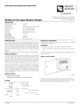
The SK-Minimon monitor module can be installed in a single gang junction
box directly behind the monitored unit. Its small size and light weight allow it
to be installed without rigid mounting (see Figure 1). The SK-Minimon is in-
tended for use in intelligent, two-wire systems where the individual address of
each module is selected using rotary switches. It provides a Class B initiating
device circuit for normally open contact fire alarm and security devices.
COMpATIBILITy REqUIREMENTS
To ensure proper operation, this module shall be connected to a compatible
Silent Knight system control panel (list available from Silent Knight).
fIgURE 1:
C1063-00
MOUNTINg AND WIRINg
NOTE: This module is intended to be wired and mounted without rigid con-
nections inside a standard electrical box. All wiring must conform to appli-
cable local codes, ordinances and regulations.
1. Connect the red (+) and black (–) wires to the positive and negative
loop power leads of the signaling line circuit (SLC).
2. Connect the violet (+) and yellow (–) wires to a two-wire, normally
open initiating loop.
3. Install the specified EOL resistor value to terminate the initiating loop.
4. Set the address on the module per job drawings.
5. Install the module in the desired mounting location.
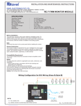
fIgURE 2. TypICAL CLASS B STyLE B INITIATINg DEvICE
CIRCUIT CONfIgURATION:
0
7
8
6
5
4
3
2
1
9
10
11
12
13
14
15
(+)
(–)
TO
NEXT
DEVICE
BLACK
RED
(+)
(–)
(+)
(–)
VIOLET
YELLOW
0
1
2
3
4
5
6
7
8
9
SIGNAL LINE CIRCUIT (SLC)
47k EOL
INCLUDED
(ELR-47k)
UL LISTED
COMPATIBLE
CONTROL
PANEL
ALL WIRING
SHOWN IS
SUPERVISED AND
POWER LIMITED
TENS
ONES
C0614-02
SpECIfICATIONS
Nominal Operating Voltage: 15-32 VDC
Average Operating Current: 375µA Maximum (group poll); 350µA (direct poll); 600µA Maximum Communicating, IDC Shorted)
EOL Resistance: 47K Ohms
Maximum SLC Wiring Resistance: 40 Ohms
Max. IDC Wiring Resistance: 1,500 Ohms
Maximum IDC Voltage: 11 Volts
Maximum IDC Current: 450µA
Temperature Range: 32˚F to 120˚F (0˚C to 49˚C)
Humidity: 10% to 93% Non-condensing
Dimensions: 1.3˝ H x 2.75˝ W x 0.5˝ D
Wire length: 6˝ minimum
I56-3444-001
12 Clintonville Road, Northford, CT 06472
203.484.7161; Fax: 203.484.7118
www.silentknight.com
/