Pulsar AWZ516 Operating instructions

Type
Operating instructions

Pulsar AWZ516 is a versatile 8-function time relay that offers precise timing and control capabilities for various applications. With its universal design and high accuracy based on a quartz oscillator, it provides repeatable settings for a wide range of timing needs. The relay can be used to extend short control impulses, control locks, electromagnets, and bistable circuits, among other functions. It also finds applications in access control systems, where it can execute logic-dependent actions based on the status of controllers, door sensors, and exit buttons.

Pulsar AWZ516 is a versatile 8-function time relay that offers precise timing and control capabilities for various applications. With its universal design and high accuracy based on a quartz oscillator, it provides repeatable settings for a wide range of timing needs. The relay can be used to extend short control impulses, control locks, electromagnets, and bistable circuits, among other functions. It also finds applications in access control systems, where it can execute logic-dependent actions based on the status of controllers, door sensors, and exit buttons.

1
PC1
AWZ 516
8-functions time relay.
v.1.0
Edition: 1 from 01.02.2008
Replaces edition: ----------
04062009
2
1. General description and intended use.
PC1 time relay enables realization 1 of 8 time-logic programs. The device characterizes by universality,
high accuracy of timing which is based on quartz oscillator and a possibility of precise, repeatable setting as
well. A relay can be used to elongation of short control impulses, for example locks, jumper of an
electromagnet and bistable control etc. A relay can be used in transition execution in project of access control
with logic dependences of a condition of the following: controller, a sensor of door opening (reed relay), exit
button etc.
2. Technical description.
2.1. Elements description.
Description of module’s connectors
12V +U modules power supply, DC voltage
GND 0V (-U) supply common
S-
Control input, reacts on system common, operation
depends on selected program
S+ Control
input, reacts on plus of system supply,
operation is dependant on selected program
R- Input resetting a relay, reacts on system common
NO Opened contact of
C Shared contact of a relay
NC Shorted contact of output relay
A description of switches, jumpers and LED
PROG (JUMPER) A jumper of programming mode
SET/RST
A button of relay setting change or a selection of
parameter while programming
TIME/MODE 10-
items switch ON/OFF, a change of parameters
while programming
LED (green):
hh
h
mm
m
ss
s
Signal of time configuration (T1/T2):
- hours decimal (0-9)
- hours (0-9)
- minutes decimal (0-5)
- minutes (0-9)
- seconds decimal (0-5)
- seconds (0-9)
LED (red)
PROG
confirmation in programming mode
LED (red)
REL
signalling of relay setting (lights = active)
2.2. A description of jumpers and switches.
PROG jumper – installation of a jumper during modules operation causes transition into the mode of
program work and times configuration selection.
SET/RST button – under normal operation turns on/off REL relay, during programming approves selected
parameter and switches to the setting of the next one.
TIME/MODE switch – in programming mode it enables a selection of program’s work and time
configuration, only one switch can be in ON position at the same time, no switch in ON position or no. 10
switch in ON position are treated as 0.
3
2.3. Visual signalling.
Normal operation:
S LED flashes with 1 Hz frequency signalling proper operation of a module and timing, in time configuration
mode it signals entering second units.
REL LED signals actuation of REL relay.
Programming mode:
hh,h,mm,ss,s LEDs signal time configuration (T1/T2).
PROG LED signals parameter’s value.
3. Relay’s programs – operation modes.
U – supply voltage
S – actuation signal, control signal (S- or S+ connection)
R – resetting signal (R- clamp)
REL – a setting of operation relay
T
U
T1T1
S
R
REL
Tryb monostabilny
T
U
S
R
REL
Tryb bistabilny
2
. Bistable mode:
S giving causes REL power-up, the
next S control signal turns off REL, giving R
signal deletes REL.
1. Monostable mode:
After giving of S control signal
power-up of REL on T1 time takes place,
REL will be turned off after timing, while
timing, S signal does not cause extension of
REL power-up, giving R signal deletes REL.
Monostable mode
Bistable mode
4
T
U
S
R
REL
Tryb zatrzask
T
U
S
R
REL
T1 T1
Tryb opóźnione zadziałanie
T
U
S
R
REL
T1
T1
Tryb opóźnione wyłączanie
T
U
S
R
REL
T1
T1
T1
Tryb odwołanie wyłączenia
4. Delayed actuation:
Giving S signal starts T1 timing, after
that, REL is actuated until it is deleted with
R signal.
5. Time
-
lag
trip:
S REL actuates immediately after
signal giving, when S signal decays it takes
place T1 timing and after this time expires
REL relay is turned off.
6.
Trip
-
out cancellation:
REL relay is actuated through T1
period after supply giving if during timing in
S input it will be given a signal to REL and
remains actuated, if a signal is not given REL
will disconnect. R giving causes REL
deletion.
3. Latch mode:
Giving S causes REL power-up, the
following S signal does not cause a reaction,
giving R signal deletes REL.
Latch mode
Delayed actuation
Time
-
lag trip
Trip
-
out cancellation
5
T
U
S
R
REL
T1
T2
T1
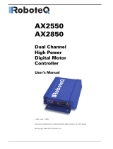
Regulowane opóźnienie zadziałania z
regulowanym czasem załączenia REL
T
U
S
R
T1 T2
T1+Ts
Ts
T2
T2
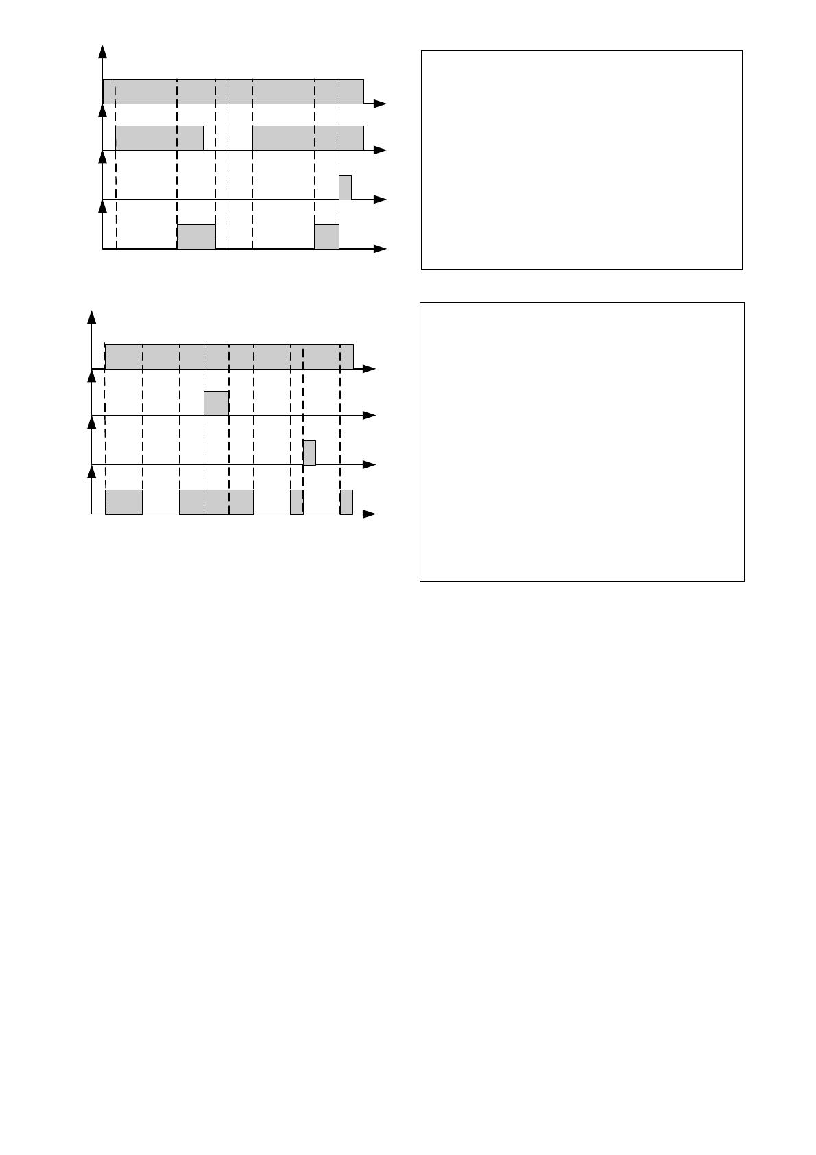
Praca cykliczna z regulacją czasów
wyłączenia T1 i załączenia T2
4. Parameters programming.
1. Install PROGRAM jumper, PROG diode will confirm the input with 10 short flashes.
2. A selection of relay’s program: select required program from 1-8 through switchover to ON position of TIME/MODE
DIPSWITCH. PROG diode will start signalling the number of selected program using flashes.
3. Press SET/RESET button, the diode will confirm selected program by fast flashes. Depending on selected program a
module switches over to T1, T2 time configuration or programming will be finished (for 2,3 mode).
4. Setting of T1/T2 actuation time:
a) hh diode flashes, entering hours decimals, PROG signals selected value
b) press SET/RESET
c) h diode lights, entering hours units, PROG diode signals selected value
d) press SET/RESET
e) mm diode lights, entering minutes decimals, PROG diode signals selected value
f) press SET/RESET
g) m diode lights, entering minutes units, PROG diode signals selected value
h) Press SET/RESET
i) ss diode lights, entering seconds decimals, PROG diode signals selected value
j) Press SET/RESET
k) S diode lights, entering seconds units, PROG diode signals selected value
5. Setting of T2 actuation time, a procedure similar to the one in point 4.
6. Programming completion, 10 short flashes of PROG diode.
7. Remove PROG armature.
7. Adjustable time
-
lag
Actuation with regulated time of REL
activation S starts T1 timing after S giving.
When the time expires and S is still active than
REL actuates on T2 period, R giving causes
REL deletion and activates awaiting on
repeated S giving.
8. Cycling with time control of T1 trip
-
out and T2 actuation
REL relay actuates on T1 period after
supply feeding, consequently T2 break timing
starts, after that T1 actuation takes place,
break timing/actuation can be locked by S
signal (level control), R signal giving deletes
REL and starts timing from the beginning).
Adjustable Time-lag trip with
regulated REL activation time
Cycling with time control of T1
trip-out and T2 actuation
6
Parameters programming
Install PROG
jumper
Fast flashes of LED PROG
Selection of operation:
Program (1-8)
PROG diode, amount of flashes =
Value of selected parameter
C
onfirmation
Hours decimal (0-9):
hh LED
SET/RESET
SET/RESET
Hours unit (0-9):
h LED
SET/RESET
SET/RESET
Minutes decimal (0-5):
mm LED
Minutes unit (0-9):
m LED
SET/RESET
Seconds decimal (0-5):
ss LED
SET/RESET
Seconds unit (0-9):
s LED
T2 timing: only mode 7
-
8
T1 timing
T2 timing
PROG diode, amount of flashes =
Value of selected parameter
Remove
PROG jumper
7
5. Factory settings:
- monostable mode of operation (program 1).
- time of relay holding T1=5s.
Note: a relay stores program’s setting and time in case of supply voltage disconnecting.
6. Technical data:
Housing
none, “open-frame” type construction, IP00
Dimensions W=35, L=87, H=23 (+/-2) [mm]
Weight net/gross 0,05 /0,09 [kg]
Assembly
assembly tape
S+ input
10,0/14,0V control (-5%/+5%)
S- input
0V (GND) control
R- input
0V (GND) control
Time range 1s ÷ 99h:59min:59s (stored in EEPROM memory )
Supply voltage
10,0÷14,0V dc (-5%/+5%)
Power consumption 9 mA/51 mA (inactive/active relay) (-5%/+5%)
Number of relays 1
Maximal operational voltage
50V dc /30Vac
Maximal operational current 10 A
Relay’s contacts NO/C/NC
Relay’s contacts <100 mOhm
Acoustic signalling of work none
Visual signalling of work LED diode: programming mode, relay setting
Conditions of work
I environmental class, 0°C / 45°C
8
WEEE MARK
The waste electrical and electronic equipment, do not mix with general household
waste. There are separate collection systems for waste electrical and electronic
equipment in accordance with legislation under the WEEE Directive and is effective
only with EU.
PRODUCER:
Pulsar K.Bogusz Sp.j.
Siedlec 150, 32-744 Łapczyca, Poland
Tel. (+48) 14-610-19-40, Fax. (+48) 14-610-19-50
e-mail:
http://
www.pulsar.pl
WARRANTY:
24 months since the sale date, 36 months since the production date.
THE WARRANTY IS VALID ONLY after presenting the invoice of the sale to which the claim refers.
  • Page 1 1
  • Page 2 2
  • Page 3 3
  • Page 4 4
  • Page 5 5
  • Page 6 6
  • Page 7 7
  • Page 8 8

Pulsar AWZ516 Operating instructions

Type
Operating instructions

Pulsar AWZ516 is a versatile 8-function time relay that offers precise timing and control capabilities for various applications. With its universal design and high accuracy based on a quartz oscillator, it provides repeatable settings for a wide range of timing needs. The relay can be used to extend short control impulses, control locks, electromagnets, and bistable circuits, among other functions. It also finds applications in access control systems, where it can execute logic-dependent actions based on the status of controllers, door sensors, and exit buttons.

Ask a question and I''ll find the answer in the document

Finding information in a document is now easier with AI