Page is loading ...

Application program for pCO¹ and pCO
2
Standard air-conditioning units
Manual version 1.2 – April 11, 2003
Program code: FLSTDMCZ0E


To save time and money!
The thorough reading of this manual will ensure proper installation and safe use of the described device.
IMPORTANT WARNINGS
BEFORE INSTALLING OR HANDLING THE APPLIANCE, PLEASE CAREFULLY READ AND
FOLLOW THE INSTRUCTIONS CONTAINED IN THIS MANUAL.
The appliance this software is intended for has been expressly designed to ensure safe operation,
provided that:
• software is installed, programmed, used and maintained by qualified personnel in full observance of the
instructions contained in this manual;
• all conditions specified and contained in the appliance installation and use manual are met.
Any other use and modification to the appliance not expressly authorised by the manufacturer shall
be considered as improper.
Liability for injuries or damage caused by improper use lies exclusively with the user.


CONTENTS
1.0
GENERAL INFORMATION........................................................................................................................................................................ 3
1.1
THE PROGRAM ..................................................................................................................................................................................... 3
1.2
THE USER TERMINAL ......................................................................................................................................................................... 3
1.3
pCO1 MAIN BOARD.............................................................................................................................................................................. 5
1.4
pCO2 MAIN BOARD.............................................................................................................................................................................. 6
1.5
ELECTRONIC EXPANSION VALVE................................................................................................................................................... 7
1.6
ACCESSORIES....................................................................................................................................................................................... 8
2.0
BUILT-IN HUMIDIFIER ............................................................................................................................................................................. 9
2.1
SETTING THE PARAMETERS TO SELECT THE HUMIDIFIER....................................................................................................... 9
2.3
HUMIDITY AND STEAM PRODUCTION CONTROL...................................................................................................................... 10
3.0
BOARD CONNECTION MANAGEMENT (pLAN)................................................................................................................................. 11
3.1
pLAN PHYSICAL CONNECTIONS ....................................................................................................................................................11
3.2
SETTING THE pLAN ADDRESS ........................................................................................................................................................11
3.3
HOW TO ASSIGN THE ADDRESSES ................................................................................................................................................11
3.4
pLAN STATUS...................................................................................................................................................................................... 12
3.5
CHECK pLAN ADDRESS.................................................................................................................................................................... 12
4.0
FIRST INSTALLATION AND SOFTWARE UPDATING .......................................................................................................................13
4.1
PROGRAM DOWNLOAD FROM HARDWARE KEY....................................................................................................................... 13
4.2
PROGRAM DOWNLOAD FROM COMPUTER................................................................................................................................. 13
4.3
INSTALLING THE DEFAULT PARAMETERS .................................................................................................................................13
4.4
LANGUAGE SELECTION................................................................................................................................................................... 13
5.0
CONFIGURATION LIST........................................................................................................................................................................... 14
5.1
DIGITAL INPUTS................................................................................................................................................................................. 14
5.2
ANALOGUE INPUTS........................................................................................................................................................................... 14
5.4
DIGITAL OUTPUTS............................................................................................................................................................................. 14
5.3
ANALOGUE OUTPUTS....................................................................................................................................................................... 15
5.5
CLOSE CONTR. UNIT WITH COILS CLOSE CONTR. UNIT WITH DIRECT EXPANS. COIL .................................................. 15
6.0
LIST OF PARAMETERS AND DEFAULT VALUES .............................................................................................................................. 16
7.0
ALARMS .................................................................................................................................................................................................... 21
7.1
ALARM RELAYS................................................................................................................................................................................. 21
7.2
TABLE OF ALARMS ........................................................................................................................................................................... 22
8.0
SCREENS.................................................................................................................................................................................................... 23
8.1
LIST OF THE SCREENS...................................................................................................................................................................... 23
9.0
TEMPERATURE CONTROL .................................................................................................................................................................... 25
9.1
CLOSE CONTROL UNITS WITH DIRECT EXPANSION COIL....................................................................................................... 25
9.2
OTHER TEMPERATURE FUNCTIONS.............................................................................................................................................. 26
9.3
CLOSE CONTROL UNITS WITH TWO WATER COILS.................................................................................................................. 26
9.4
CLOSE CONTROL UNITS WITH SINGLE WATER COIL............................................................................................................... 26
10.0
HUMIDITY CONTROL........................................................................................................................................................................ 27
10.1
CLOSE CONTROL UNITS WITH DIRECT EXPANSION COIL ................................................................................................. 27
10.2
OTHER HUMIDITY FUNCTIONS................................................................................................................................................. 28
10.3
CLOSE CONTROL UNITS WITH WATER COILS....................................................................................................................... 28
11.0
RECOVERY COIL................................................................................................................................................................................ 29
11.1
RECOVERY WITHOUT COOLING DEVICES............................................................................................................................. 29
11.2
RECOVERY WITH COOLING DEVICES ON CLOSE CONTR. UNITS WITH DIRECT EXPAN. COIL ................................. 30
11.3
RECOVERY WITH COOLING DEVICES ON CLOSE CONTROL UNITS WITH WATER COILS..........................................30
12.0
OUTLET LIMIT.................................................................................................................................................................................... 31
13.0
CONDENSER FANS............................................................................................................................................................................. 32
13.1
SINGLE OR SEPARATE COILS .................................................................................................................................................... 32
13.2
NUMBER OF PROBES ...................................................................................................................................................................32
13.3
PREVENT FUNCTION.................................................................................................................................................................... 32
13.4
SPEED-UP FUNCTION................................................................................................................................................................... 32
13.5
PRESSURE – TEMPERATURE CONVERSION............................................................................................................................ 32
14.0
TEMPERATURE SET POINT COMPENSATION.............................................................................................................................. 33
15.0
COMPRESSORS ................................................................................................................................................................................... 33
15.1
CAPACITY CONTROL................................................................................................................................................................... 33
15.2
ROTATION...................................................................................................................................................................................... 33
15.3
TIMING............................................................................................................................................................................................ 33
15.4
COMPRESSOR ALARMS............................................................................................................................................................... 34
16.0
HEATERS.............................................................................................................................................................................................. 34
16.1
HEATER ALARMS ......................................................................................................................................................................... 34
17.0
MODULATING VALVES .................................................................................................................................................................... 35
17.1
THREE-POSITION VALVES.......................................................................................................................................................... 35
17.2
0-10Volt VALVES ........................................................................................................................................................................... 35
18.0
OUTLET FAN....................................................................................................................................................................................... 35

19.0
MANUAL DEVICE MANAGEMENT ................................................................................................................................................. 35
20.0
ALARM DATA LOGGING .................................................................................................................................................................. 36
20.1
MAIN LOG (pCO1 – pCO2)............................................................................................................................................................ 36
20.2
ADVANCED LOG (pCO2).............................................................................................................................................................. 36
21.0
SUPERVISION...................................................................................................................................................................................... 37
21.1
CAREL SUPERVISOR .................................................................................................................................................................... 37
21.2
BMS.................................................................................................................................................................................................. 37
21.3
GSM PROTOCOL............................................................................................................................................................................ 37
21.4
VARIABLE DATABASE ................................................................................................................................................................ 37
22.0
EXAMPLES OF INSTALLATION....................................................................................................................................................... 40
22.1
SHARED EXTERNAL TERMINAL ............................................................................................................................................... 41
22.2
AUTOMATIC START AND STAND-BY UNITS.......................................................................................................................... 41
23.0
MASTER CONTROL............................................................................................................................................................................ 42
24.0
GLOSSARY OF TERMS....................................................................................................................................................................... 42

Standard air-conditioning units
Carel Cod. +030221421 – Rel. 1.2 – April, 11, 2003
3
1.0 GENERAL INFORMATION
1.1 THE PROGRAM
The “standard air-conditioning units” program can be used with CAREL’s pCO1 or pCO2 boards; the program manages “ED” direct expansion
or “CW” water coil air-conditioning units.
The program main functions are:
• control of temperature and humidity inside civil or technological environments
• management of 1 to 2 hermetic or semi-hermetic compressors
• management of 1 to 3 heaters
• 0-10Volt and three-position modulating heating valves
• 0-10Volt and three-position modulating cooling valves
• Carel’s external or built-in humidifier with immersed electrodes
• on-off or modulated condensing fans, pressure- or temperature-controlled
• outlet temperature control
• alarms management, alarm data logging, devices timing, warnings
• complete management of devices timing
• connection with local and BMS supervisory networks (LonWorks, Bacnet, Modbus…)
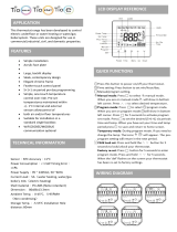
The LCD terminal displays the following data, modifiable at any time:
• measurement of connected probes and calibration, if required
• unit start and stop
• alarms detection
• programming of configuration and operative parameters with access protected by password
• controlled devices working hours and time bands with access protected by password
• programming of clock and time bands with access protected by password
• language selection among the available options (English, Italian, German, French, Spanish)
The connection with CAREL’s pLAN network allows the program to manage the following functions as well:
• automatic time or event rotation among up to 8 units
• control of temperature and humidity of max. 8 units, taking the probes of unit no. 1 as a reference
• use of only one LCD terminal for controlling up to 8 units
WARNING: to avoid tampering during device operation, the qualified personnel only shall know the passwords.
1.2 THE USER TERMINAL
The provided terminal is equipped with LCD display (4 rows x 20 columns) and can be of two types: “built-in” terminal, with 6 buttons only, or
external terminal (connected by telephone cable) with 15 buttons. Both terminals allow carrying out all program operations. The user terminal
allows displaying the unit working conditions at any time and modifying the parameters; furthermore, it may also be disconnected from the
main board, as its presence is not strictly necessary.
1.2.1 BUTTON LEDS
The EXTERNAL terminal is provided with three LEDS under the rubber buttons; the BUILT-IN terminal is provided with four LEDS. They
indicate respectively:
ON/OFF button (ext. terminal) green LED – indicates that the unit is ON; the LED blinks if OFF from supervisor, remote digital
input and time bands
ENTER button (ext. terminal) yellow LED – indicates that the device is correctly powered
ALARM button (shared term.) red LED – indicates the presence of alarms
ENTER button (built-in term.)
yellow LED – see the ON/OFF button (external terminal)
PROG button (built-in term.) green LED – indicates that a screen branch other than the Menu branch is being accessed
ESC button (built-in term.)
green LED – indicates that the Menu branch is being accessed
1.2.2 EXTERNAL TERMINAL

Standard air-conditioning units
Carel Cod. +030221421 – Rel. 1.2 – April, 11, 2003
4
Use of external terminal buttons:
Button Description
MENU
If pressed in any loop but the Manufacturer loop, returns to the Menu branch (M0) main screen
If pressed in the Manufacturer loop, returns to the manufacturer selection screen
In the Menu branch displays unit status and control probe readings
MAINT.
Goes to the first screen in the Maintenance loop (E0) first screen
The Maintenance loop is used to check the status of the devices and probes, carry out maintenance
and calibration operations, and start the manual procedure
PRINTER
Goes to the first screen in the Printer loop (B0)
The Printer loop is used to set cyclical or immediate prints
INPUTS/
OUTPUTS
Goes to the first screen in the I/O loop (I0)
The I/O loop displays the status of the digital and analogue inputs / outputs
CLOCK
Goes to the first screen in the Clock loop (L0)
The Clock loop is used to display/set the time, date and On-Off, Temperature and Humidity time
bands
SET POINT
Goes to the screen for setting the temperature and humidity set points (D0)
This loop also displays the set points modified by the compensation function, if enabled
PROGRAM
Goes to the screen to enter the user password (S0)
The User loop is used to display/set the unit parameters, referred to the devices connected
(compressors, valves, probes) and the functions enabled
+
MENU+PROG
Goes to the screen to enter the manufacturer password (Z0)
The Manufacturer loop is used to configure the type of unit (ED/CW) and select the connected
devices and the functions enabled
INFO
Displays the pLAN address of the connected board for a couple of seconds
If pressed in Menu loop of the shared terminal, it switches the displayed board
RED Temporary display of the pLAN address of the connected board
Use of silicone rubber buttons:
1. ON/OFF button: it allows air-conditioning unit start and stop
2. ALARM button: it allows alarms display / delete and buzzer switching off
3. UP ARROW button: it enables two functions: 1. scrolling the previous screens of the same branch when
the cursor is in home position; 2. increasing the value of a setting field when the cursor is on it; in case of a
selection field, the up arrow button allows displaying the previous text
4. DOWN ARROW button: it enables two functions: 1. scrolling the following screens of the same branch when the cursor is in home position; 2.
decreasing the value of a setting field when the cursor is on it; in case of a selection field, the down arrow button allows displaying the following
text
5. ENTER button: it allows moving the cursor from home position to the setting/selection field; it also allows storing the set parameters after
the cursor has left the setting fields.
1.2.3 BUILT-IN TERMINAL
As for Alarm, Up arrow, Down arrow and Enter buttons use in the built-in terminal, refer to the external terminal.
START: as the built-in terminal is not provided with ON/OFF button, unit is started/stopped by pushing buttons Esc + Enter together for 20
sec.; after pushing, the displayed screen allows executing the required operation by using button Enter.
SCREEN LOOP: as the built-in terminal is not provided with buttons for accessing the screens loop directly, simply push button Prog to
display the loops list; then, by using the arrow buttons, move the cursor on the selected loop and push Enter to access it.
ALARM PROG ESC
UP DOWN ENTER
built-in terminal

Standard air-conditioning units
Carel Cod. +030221421 – Rel. 1.2 – April, 11, 2003
5
1.3 pCO1 MAIN BOARD
The pCO1 board is described below, with reference to the general layout.
Key:
1. –G (+), G0 (-)- power supply connector
2. 250Vac fuse, 2
nd
delayed (T2 A)
3. NTC, 0/1V, 0/5V, 0/20mA, 4/20mA universal analogue inputs
4. NTC and On-Off passive analogue inputs
5. NTC passive analogue inputs
6. supply voltage yellow LED + 3 signalling LEDS
7. 0/10V analogue outputs and cutting phase PWM outputs
8. 24Vac/Vdc digital inputs
9. 230Vac or 24Vac/Vdc digital inputs
10. connector with Vrif for 5V ratiometric probes feeding and V Term for terminal feeding
11. connector for all pCO* series standard terminals and for application program download
12. pLAN local network connector
13. programming key connector
14. relay digital outputs
15. port for analogue inputs type selection
16. port for serial card insertion (Rs485 for supervisor, Rs232 for modem, Gateway protocol inverter)
17. port for clock card insertion

Standard air-conditioning units
Carel Cod. +030221421 – Rel. 1.2 – April, 11, 2003
6
1.4 pCO2 MAIN BOARD
The pCO2 board is described below, with reference to the general layout.
Key:
1. –G (+), G0 (-)- power supply connector
2. supply voltage yellow LED and overload alarm red LED
3. 250Vac fuse, 2
nd
delayed (T2 A)
4. NTC, 0/1V, 0/10V, 0/20mA, 4/20mA universal analogue inputs
5. NTC, PT1000, On-Off passive analogue inputs
6. 0/10V analogue outputs
7. 24Vac/Vdc digital inputs
8. 230Vac or 24Vac/Vdc digital inputs
9. synoptic terminal connector (external panel with direct signalling)
10. connector for all pCO* series standard terminals and for application program download
11. relay digital outputs
12. expansion card connector
13. pLAN local network connector, addressing and LED
14. port for serial card insertion (Rs485 for supervision, Rs232 for modem or Echelon interfacing)
15. port for parallel printer connection card insertion
16. port for memory expansion or programming key card insertion
17. built-in terminal (LCD, buttons and LEDS)

Standard air-conditioning units
Carel Cod. +030221421 – Rel. 1.2 – April, 11, 2003
7
1.5 ELECTRONIC EXPANSION VALVE
The EVDriver module for the control of the electronic expansion valves (EEV) for pLAN network allows the inlet overheating control for a
more efficient and versatile operation of the refrigerating unit.
Efficient because the optimisation and the stabilization of the refrigerant flow to the evaporator increase the performance of the installation
assuring at the same time the safety (less activations of the low pressure switch, less backflows of the refrigerant to the compressor,…).
Moreover, if the EEV has been properly dimensioned, using the floating or low setpoint condensation (and evaporation) pressure increase
remarkably the efficiency of the installation allowing less energy consumption and a better refrigerating yield.
Versatile because using the electronic expansion valve implies the possibility to manage refrigerating units with very different capacities and in
different operating conditions.
The use of the electronic expansion valve implies the installation not only of the EVDriver or the expansion valve themselves, but also of a
temperature sensor and a pressure transducer, both of them placed at the end of the evaporator on the refrigerant side (on the compressor inlet
pipe). Refer to the following diagram for a better understanding of the typical installation layout.
The base principle of the new control algorithm aims at the installation stability combined with, when possible, a quick achievement of the
overheating steady state.
In this sense, the priorities to be considered for an optimum control of the refrigerating installation are a high and constant refrigerating yield
rather than an extremely low and stable overheating.
The heart of the control is a PID controller that features coefficients that can be set for the overheating.
The additional controls are: LOW (Low overheating with integral time and adjustable threshold)
LOP (Low evaporation pressure, operating actually only on transients, with integral time
and adjustable threshold)
MOP (High evaporation pressure, with integral time and adjustable threshold)
HiTcond (High condensation pressure that can be activated only by condensation pressure
probe read by pCO, with integral time and adjustable threshold).
In the parameter table, the control parameters, with the thresholds and the default values, are described. The table below explains the meaning of
the parameter VALVE TYPE (see screens F1 – F2):
PARAMETER VALUE CORRESPONDING VALVE TYPE
0 Alco EX5 – EX6
1 Alco EX7
2 Alco EX8
3 Sporlan SEI 0.5 - 11
4 Sporlan SEN 25
5 Sporlan SEN 50 - 250
6 Danfoss ETS 50
7 Danfoss ETS 100
8 ---
9 Carel E2V**P
10 ---
11 Custom (other valve type)
Condensor
EEV
Evaporator
Compressor
T probe
P probe
Motor
connection
pLAN
EEV
Evaporator
T probe
P probe
Motor
connection
pLAN

Standard air-conditioning units
Carel Cod. +030221421 – Rel. 1.2 – April, 11, 2003
8
1.6 ACCESSORIES
1.6.1 PCOUMID000 CARD / PCOUMID200
This interface allows controlling the basic quantities of the OEM humidifiers produced by CAREL, that is level, feedwater conductibility and
current absorption. The pCO1 – pCO2 board directly controls all values. The interface transforms the humidifier signals into signals readable by
the cards. The cards relays directly control the humidifier functions and devices (water load, water drain and power contactor). As for
connections, refer to the instruction sheet.
to sensors to pCO
1.6.2 pCO2 (PCO2004850) AND pCO1 (PCO1004850) SERIAL CARDS
The Rs485 serial card allows interfacing pCO1 – pCO2 boards directly to a Rs485 network. The maximum available baud-rate corresponds to
19,200 (programmable by parameter). Connection with Rs485 network is executed by connecting the extractible connector to the board
terminals. As for connections, refer to the instruction sheet.
1.6.3 PCO100CLK0 CLOCK CARD FOR pCO1
The clock option card allows managing the hour and date (day, month, year) for functions such as the time bands. The clock card shall be
inserted by removing the relevant port placed on its connector.
1.6.4 PCO200KEY0 HARDWARE KEY FOR pCO2 / PCO100KEY0
The hardware key allows downloading the application program to the pCO2 board in the place of the computer; furthermore, it also allows
uploading the Flash memory contents to the key.

Standard air-conditioning units
Carel Cod. +030221421 – Rel. 1.2 – April, 11, 2003
9
2.0 BUILT-IN HUMIDIFIER
Integrated management of a Carel immersed electrode humidifier. The pCO1 - pCO2 boards manage all the functions, from the reading of the
humidifier parameters to the control of the devices (fill, drain, output) by relay. The humidifier parameters (current, conductivity, level) are not read
directly, but rather using an optional card (PCOUMID000 / 200).The built-in humidifier is available for pCO1 - pCO2 medium boards only and replaces
the electronic controller normally fitted on the humidifier. The LCD terminal features screens for controlling the humidifier. Humidifiers from 1.5 to 15
kg/h (single cylinder) and 90 kg/h (two cylinders), three-phase or single-phase, with supply voltage from 208 to 575 volts can be managed. The program
controls the steam output and the humidifier operating conditions based on the humidifier current and ambient humidity signals; furthermore, it manages
and displays all states and alarms.
2.1 SETTING THE PARAMETERS TO SELECT THE HUMIDIFIER
The following parameters are used to configure the humidifier:
• TYPE OF HUMIDIFIER
PARAMETER
VALUE RATED OUTPUT RATED VOLTAGE PHASES
POSITION OF THE
TAM JUMPER
NUMBER OF TAM
COILS
1
1.5 kg/h 208V single-phase
100 1
2
1.5 kg/h 230V single-phase
100 2
---
4
3 kg/h 208V single-phase
300 2
5
3 kg/h 230V single-phase
100 1
6
3 kg/h 208V three-phase
100 1
7
3 kg/h 230V three-phase
100 1
8
3 kg/h 400V three-phase
100 2
9
3 kg/h 460V three-phase
100 2
10
---
13
5 kg/h 208V single-phase
500 2
14
5 kg/h 230V single-phase
500 2
---
16
5 kg/h 208V three-phase
100 1
17
5 kg/h 230V three-phase
100 1
18
5 kg/h 400V three-phase
100 1
19
5 kg/h 460V three-phase
100 2
22
8 kg/h 208V three-phase
500 2
23
8 kg/h 230V three-phase
300 2
24
8 kg/h 400V three-phase
100 1
25
8 kg/h 460V three-phase
100 1
28
10 kg/h 208V three-phase
300 1
29
10 kg/h 230V three-phase
300 1
30
10 kg/h 400V three-phase
300 1
31
10 kg/h 460V three-phase
100 1
34
15 kg/h 208V three-phase
500 1
35
15 kg/h 230V three-phase
300 1
36
15 kg/h 400V three-phase
300 1
37
15 kg /h 460V three-phase
300 1
42
90 kg / h (2*45 kg/h) 400V three-phase
500 1
43
90 kg / h (2*45 kg/h) 460V three-phase
500 1
44
90 kg / h (2*45 kg/h) 575 V three-phase
500 1
Other models of humidifier will be added in the future when available.
• OUTPUT SET POINT: maximum hourly production of steam, between 20% and 100% of rated production
• TYPE OF OPTIONAL BOARD: 2 equivalent models can be chosen:PCOUMID000 and PCOUMID200
To select the end scale value of the TAM, refer to the rated current of the humidifier, displayed on screen Ih in the I/O branch ( 0= 5A, 1=10A,
2=15A, 3= 30A , 4=50A , 5=70A).

Standard air-conditioning units
Carel Cod. +030221421 – Rel. 1.2 – April, 11, 2003
10
2.3 HUMIDITY AND STEAM PRODUCTION CONTROL
The steam production of the humidifier is controlled according to:
• the humidity
• the production set on the screen (value between 30% and 100% of rated production)
Humidity control is performed by the program based on the reading of the humidity probe, the humidity set point and the humidity differential.
The program calculates the proportional humidity error, ERP:
The graph of humidifier production control is based on the rated production, set production and proportional error (ERP):
ERP = proportional humidity error
Set production: A = 100% rated output
B = 75% rated output
C = 45% rated output
The humidifier has a minimum production equal to 20% of the rated output (for technical reasons) when ERP is between 0% and 20%, and
increases as the ERP increases until reaching the set production when ERP=100%.
Below is a brief description of the algorithm embedded in the bios for the management of a humidifier with 1 or 2 immersed electrode cylinders.
In this type of humidifier, the steam is produced by boiling the water contained inside the cylinder. This occurs by simply
filling the cylinder with water and applying a voltage to the electrodes. According to the Joule effect, the current will tend
to heat the water until it boils.
The current that runs through the electrodes in the cylinder depends essentially on the voltage applied to the electrodes, the
conductivity of the water inside the cylinder and the level of the water.
The aim of the algorithm is to maintain the current that runs through the electrodes at a reference value so as to ensure the
percentage of steam production required, according to the readings of the humidity probes and the parameters set by the
user.
During evaporation, the level of the water falls, and as the current is directly proportional to the quantity of water present
in the cylinder, to keep it constant the cylinder would need to be constantly filled with minute quantities of water.
To avoid this, the current is maintained within a certain range around the reference value, by repeated “water
fill/evaporation” cycles.
As well as the level of water in the cylinder, the other factor that determines the current level is the conductivity of the water inside the cylinder. In fact,
during the fill/evaporation cycles, the conductivity of the water will tend to increase, due to the increase in the concentration of salts in the water. The
conductivity of the water inside the cylinder is measured indirectly, by calculating the time required for a complete evaporation cycle. This time is then
compared against a reference (typical for each cylinder) and, if lower, a certain quantity of water is drained and then the cylinder is topped up with less
conductive mains water.
The humidifier also features a conductivity meter that measures the conductivity of the mains water entering the appliance during the filling
cycles. In the case of high conductivity of the supply water, the control algorithm first signals a pre-alarm (that doesn't stop operation) and
then, if necessary, an alarm (that stops operation). This is essential to avoid the introduction of excessively conductive water into the cylinder,
which may compromise the correct operation of the humidifier.
Another fundamental element, installed at the top of the cylinder, is the high level sensor, used to detect any water or foam.
The high level electrodes may be activated for one of the following reasons:
- over-filling of water in the boiler – when the unit is off – due to a leak in the fill electrovalve;
- high water level when first filling the cylinder;
- high water level following the depletion of the cylinder due to fouling on the plates;
- formation of foam.
In the first case, when the high level sensor is activated, the algorithm stops operation and signals a cylinder full alarm, while in the other three
cases the humidifier responds by draining the water so as to decrease the level.
In the event of repeated activations of the high level sensor, the algorithm evaluates the possibility that the causes may be due to the presence of
foam. In this case, if after having performed a complete washing cycle (complete emptying-complete refill-complete emptying) the high level
sensor continues to be activated, the controller signals a foam alarm (that does not stop operation).
A crucial point in the operation of the humidifier is the control of any excess current levels.
In fact, whenever voltage is applied to the electrodes in the cylinder, after a period of inactivity, there may be short but very intense peaks in
current.
In the current is excessive in this initial period, the algorithm responds by immediately switching off the electrodes and performing a drain
cycle. If the excess current continues, the operation of the humidifier is stopped and a high current alarm is signalled.
The algorithm also controls the drain cycles, signalling a drain alarm if there is no appreciable decrease in current when the drain cycle starts.
Vice-versa, a no water alarm will be signalled if there is no appreciable increase in current when the humidifier is being filled with water.
ERP
SETPOINT
DIFFERENTIAL
20%
100
%
HUMIDITY % r.H
0% ERP
100% ERP
10% ERP
20% P_NOM
100% P_NOM
A
B
C
0% P_NOM
ON
I
V

Standard air-conditioning units
Carel Cod. +030221421 – Rel. 1.2 – April, 11, 2003
11
3.0 BOARD CONNECTION MANAGEMENT (pLAN)
The pLAN network identifies a physical connection between the boards (pCO1 or pCO2) and the external terminals.
pLAN=p.CO L.ocal A.rea N.etwork. Boards connection in pLAN network allows exchanging variables from a board to another, according to a
logic established by the program, to make them work together in a functional way.
The variables exchanged among the boards are already established by the program, as well as the direction they must follow and from which
they come. Therefore, they cannot be programmed by the user, who must execute the electrical connections only.
Do not execute pCO1 – pCO2 mixed connections, use exclusively boards of the same type.
3.1 pLAN PHYSICAL CONNECTIONS
The pLAN electrical connection among pCO1 or pCO2 boards is executed in parallel with 3 wires, from board to board, by using connector J11;
the data are sent through Rs485 logic; no additional device is required. As usual, terminals shall be connected to the boards by the relevant
telephone cable (code S90CONN*).
3.2 SETTING THE pLAN ADDRESS
For pLAN proper operation, the boards and the external terminals (not the built-in terminals) shall be addressed.
Even if only one board is being used, address 1 shall be set on the board and address 25 shall be set on the external terminal, if any. If the same
address is assigned to two network elements, the pLAN cannot work!
The available addresses range from 1 to 32 (in binary logic), where 32 is the total number of boards + terminals + electronic expansion valves
that can be connected with the pLAN, divided into 8 boards (addresses 1–8), 16 electronic valves (addresses 9–24) and 8 external terminals
(addresses 25–32).
In case external terminals or electronic valves are not used, the boards maximum number (8) keeps unchanged. The addresses to be assigned to
boards, valves and terminals are already established to facilitate installation and are listed in the following paragraph.
3.3 HOW TO ASSIGN THE ADDRESSES
The pLAN addresses are set with binary logic by changing the dip switch position on the back of the external terminals, on pCO2 boards (see
figure below) and inside the electronic valves drivers, with all devices compulsorily not powered; in the pCO1, address is numerical and is
assigned in a different way by an external terminal.
To read the address of a pCO2 board, external terminal or driver without remembering the binary code by heart, follow this simple rule: if the
switch is in position 1, add up value 1 for switch 1, 2 for switch 2, 4 for switch 3, 8 for switch 4, and so on. Do not add up any values for the
switches in position 0. In the example below, the selected address is: 1 + 2 + 4 + 8 = 15.
Switch1 Switch2 Switch3 Switch4
State off on off on off on off on
P 0 1 0 2 0 4 0 8
Address = P(Sw1)+P(Sw2)+P(Sw3)+P(Sw4)
On
Of
f
microprocessor
On
Of
f
printer
pCO2-pCO1 connector

Standard air-conditioning units
Carel Cod. +030221421 – Rel. 1.2 – April, 11, 2003
12
3.3.1 SETTING THE pCO1 ADDRESS
Operations to be carried out for pCO1 boards pLAN addressing:
1. Cut pCO1 board power off and connect an external terminal with pLAN address“0”
2. Power pCO1 board keeping terminal buttons Alarm + Up pressed until a screen is displayed
3. After the screen is displayed, carry out the indicated operations, that is key in the numerical pLAN address (1,2,3….) by using buttons
Up and Down, then confirm by pushing Enter
4. Cut pCO1 board power off
5. If required, assign the correct pLAN address to the external terminal, if provided
6. Power pCO1 board.
3.3.2 SETTING THE ADDRESS OF PCO2, EXTERNAL TERMINALS AND VALVE DRIVERS
This paragraph indicates the addresses to be set on pCO2 boards, external terminals and valves drivers. If pCO1 boards are being used, refer to
the previous paragraph as for boards only (as for terminals and drivers, the following indications are valid).
Each external terminal refers to one board and two electronic valves, that is:
• board add. 1 ! valves add. 9/17 ! terminal add. 25,
• board add. 2 ! valves add. 10/18 ! terminal add. 26…..
The terminals Menu main screen displays the address of the connected board in the upper right corner. Terminal add. 32 allows controlling all
boards without requiring other terminals or in addition to the other terminals; as a matter of fact, the program allows terminal with add. 32 to
access the parameters of all connected boards, one by one. Passage among the boards can be executed by simply pushing button info.
In all other program screens, the address of the connected board can be known by pushing button info.
3.4 pLAN STATUS
When starting the system, the pLAN network could undergo some problems (failed boards and terminals displays start-up) due to improper
electrical connections or to the fact that incorrect addresses have been assigned. By means of a special screen, the pLAN network state can be
displayed in real time, thus identifying which devices (boards and terminals) are properly connected and addressed. To display the special
screen, push buttons Up-Down-Enter of any network terminal simultaneously for at least 10 sec. After the first 5 seconds, a screen is displayed;
continue for another 5 seconds until the following screen is displayed:
NetSTAT
T: xx
Enter
To Exit
8
16
24
32
1
9
17
25
As it can be seen, network addresses from 1 to 32 are displayed, together with a symbol indicating if a terminal (small rectangle) or a board /
valve driver (big rectangle) is concerned. The dash indicates that the board / terminal has incorrect address or is connected improperly. In case
the symbols appear and disappear, it means that pLAN is unstable or, more probably, that repeated addresses are present. The number following
T indicates the address of the terminal being used. The example indicates that the network consists of two boards or valves drivers with address
1, 2, and of three terminals with address 3, 4, 15. After the screen is checked, cut network power off, verify connections and addresses and
power the system again.
3.5 CHECK pLAN ADDRESS
During pCO1 – pCO2 board normal operation, the board pLAN address can be checked at any time by pushing the red button (Prg+Enter in
case a built-in terminal is being used). The information appears on the display first row, covering a part of the displayed screen for 2 seconds.
The pLAN address is always displayed in the M0 Menu screen.
Add. 1 Add. 2 Add. 3 Add. 4 Add. 5 Add. 6
Card 1 Card 2 Card 3 Card 4 Card 5 Card 6 Card 7 Card 8
A
dd.
25 A
dd.
26 A
dd.
2
7
A
dd.
28 A
dd.
2
9
A
dd.
30 A
dd.
31 A
dd.
32
Terminal 1 Terminal 2 Terminal 3 Terminal 4 Terminal 5 Terminal 6 Terminal 7 Terminal 8
Add. 9 Add. 10 Add. 11 Add.12 Add. 13 Add. 14 Add. 15 Add. 16
Valve 1 Valve 3 Valve 5 Valve 7 Valve 9 Valve 11 Valve 13 Valve 15
Add 17 Add 18 Add 19 Add 20 Add 21 Add 22 Add 23 Add 24
Valve 2 Valve 4 Valve 6 Valve 8 Valve 10 Valve 12 Valve 14 Valve 16

Standard air-conditioning units
Carel Cod. +030221421 – Rel. 1.2 – April, 11, 2003
13
4.0 FIRST INSTALLATION AND SOFTWARE UPDATING
At first installation, the boards shall be programmed by DOWNLOADING the application program to the Flash buffer memory; this operation
can be performed either using a computer or the hardware key.
4.1 PROGRAM DOWNLOAD FROM HARDWARE KEY
To connect the key to the pCO2 – pCO1, proceed as follows:
1. Switch the pCO2 – pCO1 off and remove the “expansion memory” cover using a screwdriver
2. Place the key selector on
3. Insert the key into the corresponding slot
4. Press Up and Down together and switch the board on
5. Check that the red key LED comes on
6. Wait until the upload request is displayed on the LCD, then release the buttons and confirm by pressing Enter; the data transfer
operation will take approximately 10 seconds
7. Switch the pCO2 – pCO1 off, remove the key, place the cover in its original position and switch the board back on again
8. The board will now work with the program transferred from the key.
4.2 PROGRAM DOWNLOAD FROM COMPUTER
Use the kit code PC485KIT00 and the WinLOAD 32 program, proceeding as follows:
1. Connect the converter (RS232/RS485) to the mains using the transformer provided in the kit
2. Connect the converter to a free serial port on the PC, using the serial cable provided in the kit
3. Connect the converter to connector J10 on the pCO2 – pCO1 using a telephone cable (code S90CONN00*)
4. Install Winload, if Winload is not already installed on the PC
5. Run WinLOAD32 on the PC, with the board off
6. Enter in the number of the PC serial port in the field “COMM” (1 for COM1, 2 for COM2)
7. Enter “0” in the field “pCO² ADD.”
8. Switch the board on
9. Wait 30 seconds until the message “OFF LINE” becomes “ON LINE” in the WinLOAD32 program, in the lower left, or until the
yellow LED next to the dipswitch on the board starts flashing; now enter the actual board pLAN address value in the field “pCO²
ADD”; a blue light in the Winload program, in the bottom centre of the window, will start flashing.
10. In WinLOAD32, select “Upload” and then “Application”
11. Select the folder containing the application program source files
12. Use CTRL to select a series of *.iup files, if needing to load a series of languages to the pCO2-pCO1. Also select the *.blb files (for
non-pLAN applications) or the flash1.bin file in the program being loaded (for pLAN applications)
13. Click “UPLOAD” to start the file download procedure, which will take approximately 1 to 5 minutes, depending on the number of
*.iup files selected and the size of the various files
14. Wait until the message “Upload OK” appears in the progress bar
15. Disconnect the telephone cable between the board and converter; connect the external terminal (if featured), then switch the board off
and on again
NOTE: if a pLAN network with a series of boards is used, the program can be installed on the other boards without repeating the operations:
after installing the program on the first board, simply repeat steps from 8 to 14, entering the new board addresses each time in the field “pCO²
ADD” in the WinLOAD32 program.
4.3 INSTALLING THE DEFAULT PARAMETERS
Default parameters are the values assigned by CAREL to the application program main operative parameters. Parameters are assigned
automatically when executing the DOWNLOAD operation as described above. Parameters indicate timing, set points, differentials, etc… (refer
to the complete list of default values in par. 6.0).
After installing default values, the parameters can be modified within the prescribed values range.
If required, parameters can also be installed manually by the user, at any time, by the external or built-in terminal.
Operations to be carried out for default parameters manual installation:
1. Push buttons MENU + PROG and key in the Manufacturer password (1234), then push Enter
2. By pushing button Down three times, move the cursor on “INITIALISATION” (last row), then push ENTER
3. The parameters installation screen is displayed; to install, push ENTER and key in the Manufacturer password
4. WARNING: we recommend extreme care since this operation deletes all the installed parameters from the memory and replaces them
by the default parameters – after this operation, parameters cannot be restored.
5. After pushing ENTER, message “PLEASE WAIT” is displayed for some seconds.
4.4 LANGUAGE SELECTION
English is the language automatically selected, but it can be changed into: Italian, French, German, Spanish. To modify the language, operate as
follows:
1. Push buttons MENU + PROG and key in the Manufacturer password (1234), then push Enter
2. By pushing button Down three times, move the cursor on “INITIALISATION” (last row), then push ENTER
3. The parameters installation screen is displayed; push button Down three times
4. The screen with the language selection parameter is displayed, push Enter to scroll and select the language.

Standard air-conditioning units
Carel Cod. +030221421 – Rel. 1.2 – April, 11, 2003
14
5.0 CONFIGURATION LIST
The pCO1/pCO2 small/medium boards allow managing both “ED” direct expansion and “CW” water coil air-conditioning units. When started,
the program recognises the board type and size, consequently prearranging inputs and outputs, also based on the air-conditioning unit type (ED
or CW) established in the Manufacturer branch. The following tables indicate inputs and outputs configurations in the possible combinations.
The multiple items (xxx / xxx / …) indicate different inputs and outputs purposes; selection is carried out by Manufacturer screens branch
parameters. As for wiring harness, refer to the technical manual of the pCO1 and pCO2 boards.
5.1 DIGITAL INPUTS
ED CW
N. pCO1 – pCO2 SMALL pCO1 – pCO2 MEDIUM pCO1 – pCO2 SMALL pCO1 – pCO2 MEDIUM
ID 1 C1 alarm / C1 low pressure C1 alarm Flooding / fire alarm Flooding alarm
ID 2 C2 alarm / C1 high pressure C2 alarm Summer – Winter selection Summer – Winter selection
ID 3 Heater 1 thermal alarm Heater 1 thermal alarm Heater 1 thermal alarm Heater 1 thermal alarm
ID 4 Heater 2 thermal alarm Heater 2 thermal alarm Heater 2 thermal alarm Heater 2 thermal alarm
ID 5 Fire / filter / flooding alarm Dirty filters alarm Dirty filters alarm Dirty filters alarm
ID 6 Fan thermal alarm Fan thermal alarm Fan thermal alarm Fan thermal alarm
ID 7 Air flow controller alarm Air flow controller alarm Air flow controller alarm Air flow controller alarm
ID 8 Remote On-Off Remote On-Off Remote On-Off Remote On-Off
ID 9 --- C1 low pressure alarm --- Auxiliary alarm
ID 10 --- C2 low pressure alarm --- Water flow controller alarm
ID 11 --- Humidifier water level --- Humidifier water level
ID 12 --- Fire / flooding alarm --- Fire alarm
ID 13 --- C1 cond. fan thermal alarm --- ---
ID 14 --- C2 cond. fan thermal alarm --- ---
5.2 ANALOGUE INPUTS
ED CW
N. pCO1 – pCO2 SMALL pCO1 – pCO2 MEDIUM pCO1 – pCO2 SMALL pCO1 – pCO2 MEDIUM
B 1 Ambient humidity Ambient humidity Ambient humidity Ambient humidity
B 2 C1 high press. / C1 cond. temp. /
Outlet temperature (pCO2)
C1 high press. /
C1 cond. temp.
Outlet temperature Outlet temperature
B 3 C2 high press. /
C2 cond. temp. /
Recovery temperature
C2 high press. / C2 cond. temp. /
Recovery temperature (pCO2) /
Humidif. conductibility (pCO1)
Recovery temperature Recovery temperature (pCO2) /
Humidif. conductibility (pCO1)
B 4 External temperature External temperature (pCO2)
Humidifier current (pCO1)
External temperature External temperature (pCO2) /
Humidifier current (pCO1)
B 5 Ambient temperature Ambient temperature Ambient temperature Ambient temperature
B 6 Outlet temperature (pCO1)
Outlet temperature FREE FREE
B 7 --- Humidif. conductibility
(pCO2)
Recovery temperature (pCO1)
--- Humidif. conductibility (pCO2)
B 8 --- Humidifier current (pCO2)
External air temperature (pCO1)
--- Humidifier current (pCO2)
5.4 DIGITAL OUTPUTS
ED CW
N. pCO1 – pCO2 SMALL pCO1 – pCO2 MEDIUM pCO1 – pCO2 SMALL pCO1 – pCO2 MEDIUM
DO 1 Outlet fan Outlet fan Outlet fan Outlet fan
DO 2 Compressor 1 Compressor 1 Cold valve opening / single Cold valve opening / single
DO 3 Compressor 2 Compressor 2 Cold valve closing / single Cold valve closing / single
DO 4 Resist.1 / Warm valve opening Resist.1 / Warm valve opening Resist.1 / Warm valve opening Resist.1 / Warm valve opening
DO 5 Resist.2 / Warm valve closing Resist.2 / Warm valve closing Resist.2 / Warm valve closing Resist.2 / Warm valve closing
DO 6 Dehumidification Dehumidification Dehumidification Dehumidification
DO 7 Recovery
Recovery / N
on-serious alarms
Recovery
Recovery / Non-serious alarms
DO 8 Generic alarms Serious alarms Generic alarms Serious alarms
DO 9 --- C1 cond. fan / C1 capacity
control
--- ---
DO 10 --- C2 cond. fan / C2 capacity
control
--- ---
DO 11 --- Humidification --- Humidification
DO 12 --- Humidifier water load --- Humidifier water load
DO 13 --- Humidifier water drain --- Humidifier water drain

Standard air-conditioning units
Carel Cod. +030221421 – Rel. 1.2 – April, 11, 2003
15
5.3 ANALOGUE OUTPUTS
ED CW
N. pCO1 – pCO2 SMALL pCO1 – pCO2 MEDIUM pCO1 – pCO2 SMALL pCO1 – pCO2 MEDIUM
AO 1 Outlet fan / Recovery valve Outlet fan / Recovery valve Cold valve / single Cold valve / single
AO 2 Warm valve Warm valve /
Humidification
Warm valve / Recovery valve Warm valve / Recovery valve /
Humidification
AO 3 Condensing fan 1 Condensing fan 1 --- ---
AO 4 Condensing fan 2 Condensing fan 2 Outlet fan Outlet fan
5.5 CLOSE CONTR. UNIT WITH COILS CLOSE CONTR. UNIT WITH DIRECT EXPANS. COIL

Standard air-conditioning units
Carel Cod. +030221421 – Rel. 1.2 – April, 11, 2003
16
6.0 LIST OF PARAMETERS AND DEFAULT VALUES
The table below lists the parameters in the program, together with the following information: screen code (the screen code is displayed at the top
right) to assist the identification of the parameter, the default value, the minimum and maximum limits (range), and the unit of measure.
To find a specific parameter on the display, proceed as follows:
• Identify the parameter in the table below and the corresponding screen code
• Using the list of the screens (following paragraph) and the screen code, access the screen on the terminal
PARAMETER DESCRIPTION SCREEN DEFAULT USER
VALUE
RANGE UOM
Select display language A0 English En,It,Fr,De,Sp
Manual humidifier drain with unit ON A4 No No-Yes
Enter password A6 1234 0-9999
Modify outlet fan operating hours A7 0 0-99 . 0-999 hours
Modify compressor 1 operating hours A7 0 0-99 . 0-999 hours
Modify compressor 2 operating hours A7 0 0-99 . 0-999 hours
Device operating hour threshold A8 99 0-99 hours x 1000
Humidity probe calibration A9 0 -9.9 - 9.9 %RH
Condenser 1 pressure probe calibration A9 0 -9.9 - 9.9 bar
Condenser 2 pressure probe calibration A9 0 -9.9 - 9.9 bar
Ambient temperature probe calibration Aa 0 -9.9 - 9.9 ºC / ºF
Outside temperature probe calibration Aa 0 -9.9 - 9.9 ºC / ºF
Outlet temperature probe calibration Aa 0 -9.9 - 9.9 ºC / ºF
Recovery temperature probe calibration Ab 0 -9.9 - 9.9 ºC / ºF
Condenser 1 temperature probe calibration Ab 0 -9.9 - 9.9 ºC / ºF
Condenser 2 temperature probe calibration Ab 0 -9.9 - 9.9 ºC / ºF
Manual activation of digital outputs 1 – 2 – 3 Ac Off Off-on
Manual activation of digital outputs 4 – 5 – 6 Ad Off Off-on
Manual activation of digital outputs 7 – 8 Ae Off Off-on
Manual activation of digital outputs 9 – 10 Af Off Off-on
Manual activation of modulating outputs 1 – 2 Ag 0 0-10.0 Volt
Manual activation of modulating outputs 3 – 4 Ah 0 0-10.0 Volt
Manual activation of pre wash built-in humidifier Ai No No-Yes
Manual activation of total water drain built-in humidifier. Ai No No-Yes
Driver 1 valve control mode Aj Automatic Auto-Man.
Driver 1 valve manual opening steps Aj 0 0-9999 Steps
Driver 2 valve control mode Ak Automatic Auto-Man.
Driver 2 valve manual opening steps Ak 0 0-9999 Steps
Driver 1 manual release on start-up Al No No-Yes
Driver 2 manual release on start-up Am No No-Yes
Enter new Maintenance password An 1234 0-9999
Cyclical print interval H1 24 0-999 hours
Send immediate print H1 No No-Yes
Hour setting K0 current hour 0-23 Hours
Minute setting K0 current minutes 0-59 minutes
Day setting K0 current day 1-31
Month setting K0 current month 1-12
Year setting K0 current year 0-99
Enter Clock password K1 1234 0-9999
Enable temperature / humidity / On-Off time bands K2 No No-Yes
Start and end hour for On-Off time bands F1-1 and F1-2 K3 9 / 13 / 14 / 21 0-23 hours
Start and end minutes for On-Off time bands F1-1 and F1-2 K3 0 / 0 / 0 / 0 0-59 minutes
Start and end hour for On-Off time band F2 K4 14 / 21 0-23 hours
Start and end minutes for On-Off time band F2 K4 0 / 0 0-59 minutes
Select On-Off time bands (F1,F2,F3,F4) for each day K5 F2 F1-F4
Start hour temperature bands 1 and 2 K6 0 / 6 0-23 hours
Start minutes temperature bands 1 and 2 K6 0 / 0 0-59 minutes
Set point temperature bands 1 and 2 K6 23.0 see P1 ºC / ºF
Start hour temperature bands 3 and 4 K7 12 / 18 0-23 hours
Start minutes temperature bands 3 and 4 K7 0 / 0 0-59 minutes
/