Page is loading ...
Page is loading ...

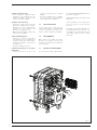
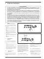
1.1 INTRODUZIONE
Le cal daie di ghi sa a condensazione 1R HE
9 ErP fun zio na no a ga so lio con una com-
bu stio ne per fet ta men te equi li bra ta e gli
elevati ren di men ti con sen tono di rea liz za re
co spi cui ri spar mi nei co sti di eser ci zio.
3
1 DESCRIZIONE DELL’ APPARECCHIO
M
R
111
113
=
=
ø 150
410
638
526
865
248
550
1410
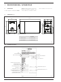
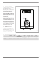
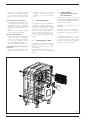
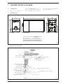
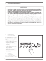
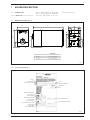
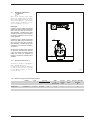
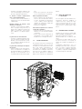
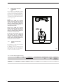
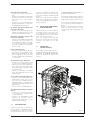
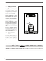
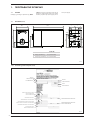
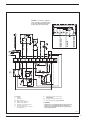
1.2 DI MEN SIO NI (fig. 1)
Fig. 1
1R HE 9 ErP
M Man da ta im pian to G 1” (UNI-ISO 228/1)
R Ri tor no im pian to G 1” (UNI-ISO 228/1)
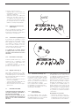
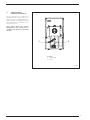
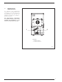
NOME
NUMERO DI SERIE
ANNO DI COSTRUZIONE
CONTENUTO D’ACQUA IN CALDAIA
PORTATA TERMICA MAX
POTENZA TERMICA MAX
PRESSIONE MAX DI ESERCIZIO
CONTENUTO A.C.S.
PORTATA TERMICA MAX A.C.S.
PRESSIONE MAX DI ESERCIZIO A.C.S.
PORTATA SANITARIA SPECIFICA
ALIMENTAZIONE ELETTRICA
POTENZA MASSIMA ASSORBITA
TIPO APPARECCHIO
CODICE
DIRETTIVA DI RIFERIMENTO
TEMPERATURA MAX ESERCIZIO
TEMPERATURA MAX ESERCIZIO A.C.S.
N° PIN
1.2.1 Targa dati tecnici (fig. 2)
Fig. 2
Page is loading ...
Page is loading ...
Page is loading ...
Page is loading ...
Page is loading ...
Page is loading ...
Page is loading ...
Page is loading ...
Page is loading ...
Page is loading ...

14
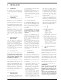
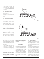
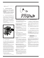
1.1 INTRODUCCION
Las calderas de hierro fundido de con-
densación 1R HE 9 ErP funcionan con
gasóleo, con una combustión perfecta-
mente equilibrada y los muy altos rendi-
mientos permiten conseguir importantes
ahorros de combustible.
1 DESCRIPCION DE LA CALDERA
CONTENUTO DE AGUA SANITARIA
MODELO
NÚMERO DE MATRÍCULA
AÑO DE CONSTRUCCIÓN
CONTENIDO DE AGUA CALDERA
CAUDAL TÉRMICA MAX
POTENCIA TÉRMICA MAX
MAX PRESIÓN DE SERVICIO
CAUDAL TÉRMICA MAX SANITARIA
PRESIÓN SANITARIA MAX
CAUDAL SANITARIO ESPECÍFICO
TENSIÓN DE ALIMENTACIÓN
POTENCIA ELÉCTRICA ABSORBIDA
TIPO
CÓDIGO
DIRECTIVA DE REFERENCIA
NÚMERO PIN
TEMPERATURA MAX DE SERVICIO
TEMPERATURA MAX DE SERVICIO SANITARIO
1.2.1 Placa de datos técnicos (fig. 2)
Fig. 2
M
R
111
113
=
=
ø 150
410
638
526
865
248
550
1410
1.2 DI MEN SIO NI (fig. 1)
Fig. 1
1R HE 9 ErP
M Ida instalación G 1” (UNI-ISO 228/1)
R Retorno instalación G 1” (UNI-ISO 228/1)
Page is loading ...
Page is loading ...
Page is loading ...
Page is loading ...
Page is loading ...
Page is loading ...
Page is loading ...
Page is loading ...

23
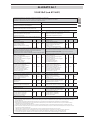
CONTENTS
1 BOILER DESCRIPTION
1.1 INTRODUCTION ....................................................................................................................................................... 24
1.2 DIMENSIONAL DETAILS
1.3 TECHNICAL FEATURES .......................................................................................................................................... 25
1.4 FUNCTIONAL DIAGRAM
1.5 COMPATIBLE BURNERS ......................................................................................................................................... 26
1.6 CONNECTION OF CONDENSATION WATER TRAP ................................................................................................. 27
2 INSTALLATION
2.1 BOILER ROOM ......................................................................................................................................................... 28
2.2 BOILER ROOM DIMENSIONS
2.3 CONNECTING UP SYSTEM
2.4 CONNECTING UP FLUE
2.5 ELECTRICAL CONNECTION
3 USE AND MAINTENANCE
3.1 COMMISSIONING THE BOILER ............................................................................................................................... 30
3.2 LIGHTING AND OPERATION
3.3 REGULAR CLEANING .............................................................................................................................................. 31
3.4 FROST POTECTION ................................................................................................................................................. 32
3.5 USER WARNINGS
3.6
DISPOSAL OF THE EQUIPMENT
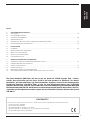
1R HE 9 ErP
ENGLISH
CONFORMITY
Our Company declares that 1R HE 9 ErP boilers comply with the essential requirements of the following direc-
tives:
- Boiler Efficiency Directive 92/42/EC
- Ecodesign Directive 2009/125/EC
- Regulation (EU) N. 813/2013 - 811/2013
- Electromagnetic Compatibility Directive 2014/30/UE
- Low Voltage Directive 2014/35/UE

24
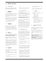
1.1 INTRODUCTION
The new 1R HE 9 ErP series of cast iron
boilers condensing they use light oil and
have a perfectly balanced combustion
with a very high thermal efficiency for
economical performance.
1 BOILER DESCRIPTION
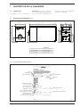
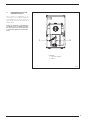
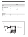
1.2 DI MEN SIO NAL DETAILS (fig. 1)
M
R
111
113
=
=
ø 150
410
638
526
865
248
550
1410
Fig. 1
MODEL
SERIAL NUMBER
YEAR OF CONSTRUCTION
WATER CONTENT IN BOILER
HEAT INPUT MAX
HEAT OUTPUT MAX
MAX OPERATING PRESSURE
CONTENTS D.H.W.
HEAT INPUT MAX D.H.W.
MAX OPERATING PRESSURE D.H.W.
D.H.W. FLOW RATE
POWER SUPPLY
MAX POWER ABSORBED
TYPE
CODE
DIRECTIVE OF REFERENCE
PIN NUMBER
MAX OPERATING PRESSURE
MAX OPERATING PRESSURE D.H.W.
1.2.1 Technical data plate (fig. 2)
Fig. 2
1R HE 9 ErP
M
C.H. flow
G 1” (UNI-ISO 228/1)
R
C.H. return
G 1” (UNI-ISO 228/1)

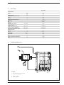
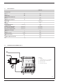
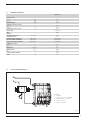
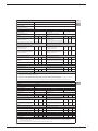
1.3 TECHNICAL FEATURES
1R HE 9 ErP
Output
80-60°C kW 74.5
50-30°C kW 78.7
Input kW 78.0
Useful efficiency measured at 100%
80-60°C % 95.5
50-30°C % 100.9
Useful efficiency measured at 30% % 103.0
PIN number 1312CR194R
Type B23P
Sections n° 9
Maximum water head bar (kPa) 4 (392)
Water content l 37.7
Smokes loss of head mbar (kPa) 0.46 (0.0450)
Combustion chamber pressure mbar (kPa) 0.98 (0.0960)
Suggested chimney depression mbar (kPa) 0.15 (0.0147)
Smokes temperature
80-60°C °C 88.1
50-30°C °C 65.1
Smokes flow m
3
n/h 79.0
Smokes volume dm
3
81.55
CO
2
% 12.5
C.H. adjustment range °C 30÷85
Weight kg 324
25
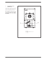
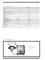
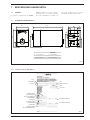
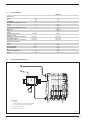
1.4 FUNCTIONAL DIAGRAM (fig. 3)
1
2
3
M
R
KEY
1 Boiler
2 Stainless steel condenser
3 Condensate drain tap
M C.H. flow
R C.H. return
Fig. 3

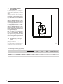
1.5 COMPATIBLE BURNERS
( EN 267)
In general, the oil burner that is compati-
ble with the boiler should use spray
of the semi solid type.
Sections 1.5.2 shows the matching table
of the burners with the boilers have been
tested with.
ATTENTION:
Water heater with Nominal Power Pn
›70kW: It is possible to use burners that
are not on the list but have the same cha-
racteristics, as long as they are confor-
ming to the standard/s, reference techni-
ques and suitable field of work.
Water heaters with Nominal Power Pn
‹70kW: It is possible to use burners that
are not on the list but have the same cha-
racteristics, as long as they are confor-
ming to the standard/s, reference techni-
ques.
When choosing the burner, pay attention
to the max electrical power absorbed by
the burner at 30% of the load and in stand-
by that should be the same or less that
those indicated in the water heater tech-
nical data.
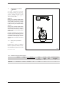
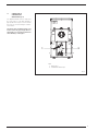
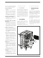
1.5.1 Burners assembly (fig. 4)
The boiler door details is shown in figure
3/a for burner mounting.
The burners must be regulated such that
the CO2
value is that indicated in point
1.3, with a tolerance of ± 5%.
26
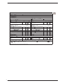
1.5.2 Permanent feeding burners
Model Code Nozzle Atomising Pump Class Adsorbed power
Type ø angle pressure NOx consumption
bar W
1R HE 9 ErP SIME MACK 4 8099010 DELEVAN 0,75 60°W 11,0 1 163
110
M8
150
Fig. 4

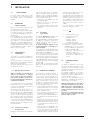
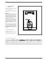
1.6 CONNECTION OF
CONDENSATION
WATER TRAP (fig. 5)
The drip board and its water trap must
be connected to a civil drain through a
pipe (ø 25) with a slope of at least 5 mm
per metre to ensure drainage of conden-
sation water.
The plastic pipes normally used for civil
drains are the only type of pipe which is
appropriate for conveying condensation
to the building’s sewer pipes.
27
1
2
Fig. 5
KEY
1 Drain hose
2 Condensate drain tap

2.1 BOILER ROOM
The boiler room should feature all the
characteristics required by standards
governing liquid fuel heating systems.
2.2 BOILER ROOM
DIMENSIONS
Position the boiler body on the founda-
tion bed, which should be at least 10 cm
high. The body should rest on a surface
allowing shifting, possibly by means of
sheet metal.
Leave a clearance between the boiler
and the wall of at least 0.60 m, and
between the top of the casing and the
ceiling of 1 m (0.50 m in the case of boil-
ers with incorporated D.H.W. tank).
The ceiling height of the boiler room
should not be less than 2.5 m.
2.3 CONNECTING
UP SYSTEM
When connecting up the water supply to
the boiler, make sure that the specifica-
tions given in fig. 1 are observed.
All connecting unions should be easy to
disconnect by means of tightening rings.
A closed expansion tank system must
be used.
2.3.1 Filling the
water system
Before connecting the boiler, thorough-
ly flush the system to eliminate scale
which could damage the appliance.
Filling must be done slowly to allow any
air bubbles to be bled off through the air
valves.
In closed-circuit heating systems, the
cold water filling pressure and the pre-
charging pressure of the expansion ves-
sel should be no less than or equal to the
height of the water head of the installa-
tion (e.g. for water head of 5 meters, the
vessel pre-charging pressure and instal-
lation filling pressure should be at least
0.5 bar/49 kPa).
2.3.2 Characteristics
of feedwater
Water supplying the heating circuit must
be treated in accordance with UNI-CTI
8065 standards.
It is absolutely essential to treat water
in the heating system in the following
cases:
– For extensive systems (with high con-
tents of water).
– Frequent addition of water into the sy-
stem.
– Should it be necessary to empty the
system either partially or totally.
2.3.3 D.H.W. storage tank
The 1R HE 9 ErP boilers may be matched
with the separate boiler units.
The glass enamelled D.H.W. storage
tank comes with a magnesium anode
to protect the boiler and an inspection
flange for checking and cleaning.
The magnesium anode must be checked
annually and replaced if it is worn.
Fit a safety valve calibrated to 6 bar (588
kPa) on the tubing of the cold water sup-
ply to the boiler unit.
An case the system pressure is excessive
fit an appropriate pressure reducer.
If the safety valve calibrated to 6 bar (588
kPa) frequently intercepts, fit an expan-
sion vessel with a capacity of 8 litres and
a maximum pressure of 8 bar (784 kPa).
The tank should be of the membrane
type, made of natural rubber “caou-
tchouc”, which is suitable for foods.
2.4 CONNECTING UP FLUE
The flue is of fundamental importance for
the proper operation of the boiler; if not
installed in compliance with the stand-
ards, starting the boiler will be difficult
and there will be a consequent formation
of soot, condensate and encrustation.
The flue used to expel combustion prod-
ucts into the atmosphere must meet the
following requirements:
– be constructed with waterproof mate-
rials, and resistant to smoke tempera-
ture and condensate;
– be of adequate mechanical resilience
and of low heat conductivity;
– be perfectly sealed to prevent cooling
of the flue itself;
– be as vertical as possible; the terminal
section of the flue must be fitted with
a static exhaust device that ensures
constant and efficient extraction of
products generated by combustion;
– to prevent the wind from creating
pressure zones around the chimney
top greater than the uplift force of
combustion gases, the exhaust out-
let should be at least 0.4 m higher
than structures adjacent to the stack
(including the roof top) within 8 m;
– have a diameter that is not inferior
to that of the boiler union: square or
rectangular-section flues should have
an internal section 10% greater than
that of the boiler union;
– the useful section of the flue must
conform to the following formula:
S resulting section in cm
2
K reduction coefficient for liquid
fuels:
– 0.045 for firewood
– 0.030 for coal
– 0.024 for light oil
– 0.016 for gas
P boiler input in kcal/h
H height of flue in meters, measured
from the flame axis to the top of
the flue reduced by:
– 0.50 m for each change of direc-
tion of the connection union
between boiler and flue;
– 1.00 m for each metre of union
itself.
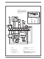
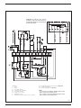
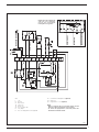
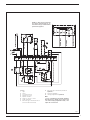
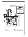
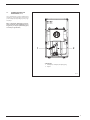
2.5 ELECTRICAL CONNECTION
(fig. 6)
The boiler is fitted with an electricity
cable, and requires a 1ph - 230V - 50Hz
power supply through the main switch
protected by fuses.
The room thermostat (required for
enhanced room temperature control)
should be installed as shown in fig. 6.
Connect the burner with the cable sup-
plied.
NO TE: Device must be connected to an
efficient earthing system.
SI ME de cli nes all responsibility for inju-
ry caused to persons due to failure to
earth the boiler.
Always turn off the power supply before
doing any work on the electrical panel.
28
P
S = K
√H
2 INSTALLATION

29
GRIGIO-GREY
GRIGIO-GREY
BLU-BLUE
BLU-BLUE
MARRONE-BROWN
MARRONE-BROWN
Fig. 6
KEY
L Line
N Neutral
IG Main switch
TS Safety stat
TC Boiler stat
SA Green voltage LED
PI C.H. pump
B Direct Feeding Burner (not supplied)
B1 Permanent Feeding Burner (optional)
TA Room stat
OP Programmer’s clock (optional)
NO TE:
- When a room stat (TA) is to be fitted remove the link
between terminal 4 and 5 on the connector plug.
- To connect the programmer’s clock (OP), remove the
link between terminals 5 and 8.
NOTE: The brown (capped off)
cable has to be exclusively
used in case of permanent
feeding burners (type B1).

3.1 COMMISSIONING THE BOILER
When commissioning the boiler always
make sure that:
– the system has been filled with water
and adequately vented;
– the flow and return valves are fully
open;
– the flue and chimney are free from
obstructions;
– the electrical connections to the mains
and the earthing are correct;
– no flammable liquids or materials are
near the boiler;
– check that the circulating pump is not
locked.
3.2 LIGHTING AND OPERATION
3.2.1 Lighting the boiler (fig. 7)
To light the boiler proceed as follows:
– check that the “Testing Certificate”
has been removed from inside the
combustion chamber;
– switch on the main switch and verify
that the green LED turns on to confirm
30
3 USE AND MAINTENANCE
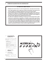
WARNINGS
– In case of failure or malfunction of the equipment, contact authorised technical
staff.
– For safety reasons, the User cannot access the internal parts of the appliance. All
operations involving the removal of protections or otherwise the access to dan-
gerous parts of the appliance must be performed by qualified personnel.
– The appliance can be used by children under 8 years and by persons with redu-
ced physical, sensory or mental capabilities, or lack of experience or knowledge,
provided they are under supervision or after they have been given instructions
concerning the safe handling of the appliance and the understanding of the dan-
gers inherent to it. Never let children play with the appliance. Children without
supervision must not carry out cleaning and maintenance meant to be carried out
by the user.
60ϒC
Fig. 7

the presence of voltage.The burner
will start.
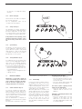
3.2.2 Boiler stat (fig. 8)
Turn the boiler stat knob to a tempera-
ture no lower than 60°C.
The set temperature value can be
checked on the thermometer.
3.2.3 Safety stat (fig. 9)
The manually reset safety stat trips to
switch-off the burners immediately when
the boiler temperature exceeds 100°C.
To restart the boiler, unscrew the black
cover and press the button underneath.
If the problem occurs frequently, call an
authorised technical assistance centre
for the necessary checks to be carried
out.
3.2.4 System filling
Periodically check the pressure values
of the hydrometer mounted onto the
system, when the system is cold, should
range between 1 and 1.2 bar (98 and
117.6 kPa). If the pressure is less than 1
bar (98 kPa), reset the system.
3.2.5 Turnig OFF boiler (fig. 7)
To temporarily turn off the boiler turn
off the electricity supply by pressing the
main switch. The following operations
must be carried out if the plant will not
be in use for a lengthy period of time:
–
position the main switch of the plant on off;
– turn the fuel and water taps of the cen-
tral heating plant off;
– empty the central heating plant if there
is danger of frost:
3.3 REGULAR CLEANING
Maintenance of the boiler should be
carried out annually by an authorised
service engineer. Disconnect the boiler
from the electrical supply before ser-
vicing or maintenance is carried out.
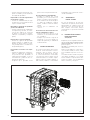
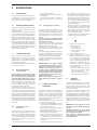
3.3.1 Smoke side boiler (fig. 10)
To carry out cleaning of the smoke pas-
sages remove the screws that fix the
door to the body of the boiler and with the
special cleaning brush clean the internal
surfaces and the smoke evacuation tube
well, removing any deposits.
Once the maintenance is compled, the
baffles have to be fitted onto the original
positions.
The maintenance operations can be car-
ried out without removing the burner.
3.3.2 Fault finding
Herefater we outline a number of poten-
tial problems that may occur on the
appliance and the relevant list of actions
required. A working fault, in most cases,
provocates the “lock out” signal onto the
control panel of the control box.
When this light turns on, the burner can
operate again only after the reset button
has been pressed; if this has been done
and a regular ignition occurs, it means
the failure can be defined momentary
and not dangerous. On the contrary,
if the “lock out” stays, the cause of
the fault, as well as the relevant action
must be made according to the follow-
ing chart:
The burner does not ignite
– Check the electric connections.
– Check the regular fuel flow, the clean-
ness of the filters, of the nozzle and air
vent from the tube.
– Check the regular spark ignition and
the proper function of the burner.
The burner ignites regularly but the
flame goes out immediately
– Check the flame detection, the air
calibration and the function of the
appliance.
Difficulty in regulating the burner and/
or lack of yield
– Check: the regular flow of fuel, the
cleanness of the boiler, the non
obstruction of the smoke duct, the
real input supplied by the burner and
its cleanness (dust).
31
60ϒC
Fig. 8
60ϒC
Fig. 9

The boiler gets dirty easily
– Check the burner regulator (smoke
analysis), the fuel quantity, the flue
obstruction and the cleanness of the
air duct of the burner (dust).
The boiler does not heat up
– Control the cleanness of the shell, the
matching, the adjustment, the burner
performances, the pre-adjusted tem-
perature, the correct function and
position of the regulation stat.
– Make sure that the boiler is sufficiently
powerful for the appliance.
Smell of unburnt products
– Control the cleanness of the boiler
shell and the flue, the airtightness of
the boiler and of the flue ducts (door,
combustion chamber, smoke ducts,
flue, washers).
– Control the quality of the fuel.
Frequent intervention of the boiler
shutoff valve
– Control the presence of air in the
system, the function of the circulation
pumps.
– Check the load pressure of the appli-
ance, the efficiency of the expansion
tanks and the valve calibration.
3.4 FROST PROTECTION
In the event of frost, ensure that the
central heating plant is functional and
effective frost protection interlocks are
in place to protect against frost damage
3.5 USER WARNINGS
When faults occur and/or the equip-
ment does not operate correctly, turn
the boiler off and contact the authorised
service engineer.
3.6
DISPOSAL OF THE EQUIPMENT
Once it reaches the end of its operating life,
the equipment MUST BE RECYCLED in line
with current legislation.
IT MUST NOT be disposed of together with
urban waste.
It can be handed over to recycling centres,
if there are any, or to retailers that offer
this service.
Recycling prevents potential damage to the
environment and health. It allows to reco-
ver a number of recyclable materials, with
considerable savings in terms of money
and energy.
32
Fig. 10
Page is loading ...

34
1.1 INTRODUCTION
Les chaudières en fonte à condensation
1R HE 9 ErP fonctionnent au fuel avec
une combustion parfaitement équilibrée
et avec un très haut rendement qui per-
mettent de réaliser de très importantes
économies de combustible.
1 DESCRIPTION DE LA CHAUDIERE
1.2 DI MEN SIO NS D’ENCOMBREMENT (fig. 1)
M
R
111
113
=
=
ø 150
410
638
526
865
248
550
1410
Fig. 1
MODÈLE
NUMÉRO DE SÉRIE
ANNÉE DE CONSTRUCTION
CONTENANCE EAU CHAUDIÈRE
DÉBIT CALORIFIQUE MAX
PUISSANCE THERMIQUE MAX
PRESSION MAX DE SERVICE
CONTENANCE EAU SANITAIRE
DÉBIT CALORIFIQUE MAX SANITAIRE
PRESSION MAX DE SERVICE SANITAIRE
DÉBIT SANITAIRE SPÉCIFIQUE
ALIMENTATION ÉLECTRIQUE
PUISSANCE ÉLECTRIQUE ABSORBÉE
TYPE
CODE
DIRECTIVE DE RÉFÉRENCE
NUMÉRO PIN
TEMPÉRATURE MAX DE SERVICE
TEMPÉRATURE MAX DE SERVICE SANITAIRE
1.2.1 Technique plaque de données (fig. 2)
Fig. 2
1R HE 9 ErP
M
Départ installation
G 1” (UNI-ISO 228/1)
R
Retour installation
G 1” (UNI-ISO 228/1)
Page is loading ...
Page is loading ...
Page is loading ...
Page is loading ...
Page is loading ...
Page is loading ...
Page is loading ...
Page is loading ...
Page is loading ...
Page is loading ...
Page is loading ...
Page is loading ...
Page is loading ...
Page is loading ...
Page is loading ...
Page is loading ...
Page is loading ...
Page is loading ...
Page is loading ...
Page is loading ...
Page is loading ...
Page is loading ...
Page is loading ...
Page is loading ...
Page is loading ...
Page is loading ...
Page is loading ...
Page is loading ...
Page is loading ...
Page is loading ...
Page is loading ...
Page is loading ...
Page is loading ...
Page is loading ...
Page is loading ...
Page is loading ...
Page is loading ...
Page is loading ...
Page is loading ...
Page is loading ...
Page is loading ...

Fonderie Sime S.p.A - Via Garbo, 27 - 37045 Legnago (Vr)
Tel. +39 0442 631111 - Fax +39 0442 631292 - www.sime.it
Documentation Dpt. Fonderie Sime S.p.A.
-
 1
1
-
 2
2
-
 3
3
-
 4
4
-
 5
5
-
 6
6
-
 7
7
-
 8
8
-
 9
9
-
 10
10
-
 11
11
-
 12
12
-
 13
13
-
 14
14
-
 15
15
-
 16
16
-
 17
17
-
 18
18
-
 19
19
-
 20
20
-
 21
21
-
 22
22
-
 23
23
-
 24
24
-
 25
25
-
 26
26
-
 27
27
-
 28
28
-
 29
29
-
 30
30
-
 31
31
-
 32
32
-
 33
33
-
 34
34
-
 35
35
-
 36
36
-
 37
37
-
 38
38
-
 39
39
-
 40
40
-
 41
41
-
 42
42
-
 43
43
-
 44
44
-
 45
45
-
 46
46
-
 47
47
-
 48
48
-
 49
49
-
 50
50
-
 51
51
-
 52
52
-
 53
53
-
 54
54
-
 55
55
-
 56
56
-
 57
57
-
 58
58
-
 59
59
-
 60
60
-
 61
61
-
 62
62
-
 63
63
-
 64
64
-
 65
65
-
 66
66
-
 67
67
-
 68
68
-
 69
69
-
 70
70
-
 71
71
-
 72
72
-
 73
73
-
 74
74
-
 75
75
-
 76
76


Ask a question and I''ll find the answer in the document
Finding information in a document is now easier with AI
in other languages
- italiano: Sime 1R HE 9 ErP Manuale utente
- français: Sime 1R HE 9 ErP Manuel utilisateur
- español: Sime 1R HE 9 ErP Manual de usuario
- Deutsch: Sime 1R HE 9 ErP Benutzerhandbuch
- Nederlands: Sime 1R HE 9 ErP Handleiding
Related papers
-
Sime ESTELLE HE 4 ErP User manual
-
-
-
-
-
-
-
-
-
Other documents
-
Riello Start Condens 25 IS Installer And User Manual
-
Ferroli PEGASUS D 30 K 100 LN Instructions For Use, Installation And Maintenance
-
Riello RX 500 S PV User manual
-
Master BV 110-290 E B 230-360 Owner's manual
-
Unical ALKON 140 EXT Installation guide
-
-
 SANT ANDREA GTGNB Owner's manual
-
 Unical !DEA Installation guide
-
La Nordica LNK40 Owner's manual
-
 Unical KUTter B inox Installation guide


